
Summary of Contents for Metcom Solutions MCS301
- Page 1 MCS301 Polyphase Smart Meter Product Manual Document name MCS301 Manual_EN_V24.doc Document number: Revision 1.25 Date of version: 15.11.2019...
- Page 2 NOTICE The information contained in this document is subject to change without notice. MetCom Solutions GmbH shall not be liable for errors contained herein or for incidental or consequential damages in connection with the furnishing, performance, or use of this material.
-
Page 3: Table Of Contents
6.5.3.3 Activation of M-Bus installation (Menu option „Slave_InSTALL“) ......31 6.6 Optical display sensor ....................31 Measurement functionality ..................... 32 7.1 Measuring principle ....................... 32 7.1.1 Calculation of voltage and current ................ 32 MCS301 meter - product Manual 1.25 MetCom Solutions GmbH... - Page 4 Load profile........................53 13.1 General profile Structure ..................... 53 13.1.1 Sort method ......................53 13.1.2 Buffer reading ...................... 54 13.1.3 Profile Status ....................... 54 13.1.4 Effect of events on load profiles ................55 MCS301 meter - product Manual 1.25 MetCom Solutions GmbH...
- Page 5 19.1.2 Wired M-Bus interface ..................92 19.1.3 RS485 interface ....................93 19.1.4 RS232 interface ....................93 19.1.5 Ethernet interface ....................94 19.1.6 Communication module interface ................. 94 19.1.7 Simultaneous communication ................94 MCS301 meter - product Manual 1.25 MetCom Solutions GmbH...
- Page 6 26.1 General ........................118 26.2 Device ID’s for M-Bus meters ................... 120 26.3 M-Bus profile ......................120 26.4 Connect/Disconnect for M-Bus meters ..............120 26.5 Event management for M-Bus meters ............... 121 MCS301 meter - product Manual 1.25 MetCom Solutions GmbH...
- Page 7 Type key ........................135 32.1 Type key for HW version up to V1.3 ................135 32.2 Type key for HW version from V1.5 onwards ............136 Technical data of the MCS301 ..................137 Connection diagram ....................138 34.1 Complete connection diagram .................. 138 34.2 Mains connection diagram ..................
-
Page 8: Overview
• 3ph meter, CT/VT connected with wide range power supply • 3ph meter, DC connected This manual describes the feature set of the different FW versions of the MCS301, which is displayed on the LCD as well as readout through any interface using below OBIS codes: CT &... -
Page 9: Referenced Documents
IDIS-S02-001b C1 w1.1 IDIS Pack2 IP Profile corrigendum1, Ed 2.0 corr. 12.01.2015 IDIS-S02-004 - object model Pack2 Ed2.0.xls V2.26 26.08.2016 160226 w1.12 IDIS-S03-001 Pack3 IP profile-X.pdf W1.14 16.09.2016 FID2 -Interoperability Specification.pdf V1.1 01.06.2016 FID2-Object list.pdf V1.1 01.06.2016 MCS301 meter - product Manual 1.25 MetCom Solutions GmbH... -
Page 10: Definitions And Abbreviations
External current transformer External voltage transformer Under voltage Swell Over voltage Low level security, (Password) High level security, (Key exchange) Day light saving Time of use, tariffication IDIS Interoperable Device Interface Specification MCS301 meter - product Manual 1.25 MetCom Solutions GmbH... -
Page 11: Meter Standards
MCS301 - 3ph meter Page 11 of 142 Meter standards The MCS301 meter is tested and approved according below standards: • IEC standards o EN62052-11 basic standard for electronic meters o EN62053-21 active energy meters, class 1 and 2 o EN62053-22... -
Page 12: Safety And Maintenance Information
The owner of the meter responds specially for the protection of the persons, for prevention of material damage and for training of personnel. MetCom Solutions provides training courses related to the above mentioned items. Safety instructions The following safety regulations must be observed: •... -
Page 13: Maintenance
Waste Electric and Electronic (WEEE) Directive! Disposal The components used in the MCS301 are largely recyclable according to the requirements of the environmental management standard ISO14001. Specialized disposal and recycling companies are responsible for material separation, disposal and recycling. The following table identifies the components and their treatment at the end of the life cycle. -
Page 14: Basic Functionality
If phase and neutral conductor will be connected in a wrong way the meter displays an alarm. All meter types of the MCS301 are earth fault protected; in that case the meter can handle a voltage of 1.9Un for more than 12h. -
Page 15: General Concept
The meter is based on below concept: Figure 1: General concept of the meter The meter firmware (FW) is split in two parts - metrological relevant FW - application relevant FW (remote or local download supported) MCS301 meter - product Manual 1.25 MetCom Solutions GmbH... -
Page 16: Application Relevant Fw Part
Internal supercap and battery support • Demand reset button • Alternate button • tamper detection (terminal & main cover opening, magnet detection, …) • 2 metrological LED’s • 6x 230V, 100mA outputs MCS301 meter - product Manual 1.25 MetCom Solutions GmbH... -
Page 17: Meter Construction
MCS301 - 3ph meter Page 17 of 142 5 Meter construction This section describes the mechanical construction of the MCS301 meter. The PCB of the meter is mounted in a rectangular case and meets or exceeds the following standards: •... -
Page 18: Outside Meter Dimensions
MCS301 - 3ph meter Page 18 of 142 Outside meter dimensions Figure 3: Outside dimension of the meter MCS301 meter - product Manual 1.25 MetCom Solutions GmbH... -
Page 19: Meter Case Parts
Page 19 of 142 Meter case parts 5.3.1 Terminal block The MCS301 can be provided with different terminal blocks for DC and CT meter type 5.3.1.1 CT connected terminal block Figure 4: terminal block of the CT connected meter MCS301 meter - product Manual 1.25... -
Page 20: Direct Connected (Dc) Terminal Block
MCS301 - 3ph meter Page 20 of 142 5.3.1.2 Direct connected (DC) terminal block Figure 5: terminal block of the direct connected meter MCS301 meter - product Manual 1.25 MetCom Solutions GmbH... -
Page 21: Main Cover
5.3.2 Main cover Meter cover is made of non-transparent high quality self-extinguishing UV stabilized polycarbonate that can be recycled. The MCS301 meter is equipped with a meter main cover opening detector. Figure 6: main cover of the meter 5.3.3 Terminal cover The meter provides different terminal covers: •... -
Page 22: Communication Module Cover
Remark: The communication module is equipped with a module removal detector. Sealing The meter can be sealed with different type of sealing: a) Pin seal Figure 9: Pin seal b) Plastic seal Figure 10: Plastic sealing - standard MCS301 meter - product Manual 1.25 MetCom Solutions GmbH... -
Page 23: Name Plate
MCS301 - 3ph meter Page 23 of 142 5.5 Name plate The MCS301 nameplate is laser printed on the meter cover: - Property Number - Accuracy Class - Serial Number - LED test pulse constants RA and RL - Manufacturer (name and address) -
Page 24: Display Control
4,0 • Digit size (OBIS code): 5,5 x 2,8 The digits for the LC display of the MCS301 you will find in Fig 15: Figure 12: display of the meter MCS301 meter - product Manual 1.25 MetCom Solutions GmbH... -
Page 25: Back Lightened Display
The back lightened display will be activated for a configurable time (5 ... 255s) by pressing the alternate or the demand reset button. This feature will be available even if the meter is not connected to the main power. MCS301 meter - product Manual 1.25 MetCom Solutions GmbH... -
Page 26: Display Formats
12 on the right side of the LCD. Active energy register, +A 1.8.0 Active energy register, -A 2.8.0 MCOR FW name 0.2.0 MCOR FW signature 0.2.8 Metrological relevant error code F.F or 97.97.1 MCS301 meter - product Manual 1.25 MetCom Solutions GmbH... -
Page 27: Display Modes
• Display mode menu "Reset mode" - “tESt” High-resolution test mode for testing purposes - “CELL connect” Activation of Push Mode to connect to HES - “Slave InStALL” Activation of M-Bus installation MCS301 meter - product Manual 1.25 MetCom Solutions GmbH... -
Page 28: Scroll Mode
Parameter of the scroll mode: - scroll time (1 … 20s) - number of display for changeable entries (scroll list 1): - number of display for protected entries (scroll list 2): MCS301 meter - product Manual 1.25 MetCom Solutions GmbH... -
Page 29: Different Display Mode
“Std_data). The main difference between this 2 lists is, that the “SEr-dAtA” list can be set without breaking the certification seal. • number of display entries: MCS301 meter - product Manual 1.25 MetCom Solutions GmbH... -
Page 30: Load Profile 1 - "Standard Profile" - (Menu Option
6.5.2.5 Load profile 2 – “Daily profile” - (Menu Option "P.02") Details about recording load profile 2 (“Daily profile”) data are described in chapter 13.3. The display menu acts as explained in chapter 6.5.2.3. MCS301 meter - product Manual 1.25 MetCom Solutions GmbH... -
Page 31: Reset Mode (R-Button Menu)
The optical sensor reacts on a light which is going to the receive LED of the optical interface. Figure 14: optical interface with optical sensor (ACOR FW 02.02.11) MCS301 meter - product Manual 1.25 MetCom Solutions GmbH... -
Page 32: Measurement Functionality
DFT processor. The DFT processor computes the fundamental and harmonic components based on the measured line frequency and sampling rate of 8kHz. The THD measurement is done according below formula voltage THD = MCS301 meter - product Manual 1.25 MetCom Solutions GmbH... -
Page 33: Measuring Methods
The meter is counting the energy of every phase dependent on the sign of the phase energy Example: P1 = 40W P2 = -25W P3 = 50W +P = 40 + 50 = 90W -P = 25 = 25W MCS301 meter - product Manual 1.25 MetCom Solutions GmbH... -
Page 34: Measurement Data
Transformer losses, -I*I*h 1-0:83.8.5.255 Transformer losses, /U*U*h/ with 1-0:83.8.19.255 normalized R =1MOhm *) line losses, /I*I*h/ with normalized 1-0:83.8.20.255 =1Ohm *) Table 2: list of 3ph energy register with OBIS codes (ACOR FW02.02.11) MCS301 meter - product Manual 1.25 MetCom Solutions GmbH... -
Page 35: Energy Measurement (3Ph Values) - Since Last Demand Reset
1-0:27.8.0.255 1-0:47.8.0.255 1-0:67.8.0.255 reactive energy, R4 1-0:28.8.0.255 1-0:48.8.0.255 1-0:68.8.0.255 apparent energy, +S 1-0:29.8.0.255 1-0:49.8.0.255 1-0:69.8.0.255 apparent energy, -S 1-0:30.8.0.255 1-0:50.8.0.255 1-0:70.8.0.255 Table 4: list of 1ph energy register with OBIS codes MCS301 meter - product Manual 1.25 MetCom Solutions GmbH... -
Page 36: Maximum Demand Measurement
=> Stop of current demand measurement, restart of new demand period • time synchronization deviation <= configurable interval => Ongoing demand period • time synchronization deviation >= configurable interval => Stop of current demand measurement, restart of new demand period MCS301 meter - product Manual 1.25 MetCom Solutions GmbH... -
Page 37: Instantaneous Measurement
Current angle, Ux-Ix 1-0:81.7.4.255 1-0:81.7.15.255 1-0:81.7.26.255 Current angle, Ix-Ux 1-0:81.7.40.255 1-0:81.7.51.255 1-0:81.7.62.255 frequency in any phase 1-0:14.7.0.255 Neutral current calculation 1-0:91.7.3.255 Internal temperature 0-0:96.9.0.255 Table 7: list of instantaneous PQ data without harmonics MCS301 meter - product Manual 1.25 MetCom Solutions GmbH... -
Page 38: Instantaneous Measurement Data - Pq Data With Harmonics + Thd
15.te harmonic, current 1-0:31.7.15 1-0:51.7.15 1-0:71.7.15 THD, voltage 1-0:32.7.124 1-0:52.7.124 1-0:72.7.124 THD, current 1-0:31.7.124 1-0:51.7.124 1-0:71.7.124 list Table 8: of instantaneous PQ data with harmonics and THD *) available with MCOR FW 1-0:01.01.25 MCS301 meter - product Manual 1.25 MetCom Solutions GmbH... -
Page 39: Average- / Min- / Max- Interval Data
11.te harmon, current 1-0:31.25.11 1-0:51.25.11 1-0:71.25.11 13.te harmon., current 1-0:31.25.13 1-0:51.25.13 1-0:71.25.13 15.te harmon., current 1-0:31.25.15 1-0:51.25.15 1-0:71.25.15 Table 9: list of last average data *) available with MCOR FW 1-0:01.01.25 MCS301 meter - product Manual 1.25 MetCom Solutions GmbH... -
Page 40: Last Minimum Values
1-0:30.26.0.255 1-0:50.26.0.255 1-0:70.26.0.255 Voltage 1-0:32.26.0.255 1-0:52.26.0.255 1-0:72.26.0.255 Current 1-0:31.26.0.255 1-0:51.26.0.255 1-0:71.26.0.255 power factor, total 1-0:13.26.0.255 1-0:33.26.0.255 1-0:53.26.0.255 1-0:73.26.0.255 10 frequency in any phase 1-0:14.26.0.255 Table 11: list of last maximum data MCS301 meter - product Manual 1.25 MetCom Solutions GmbH... -
Page 41: Primary / Secondary Measurement
• VT ratio in the range of 1 … 4000 Both parameters (CT and CT/VT ratio) can be displayed on the LCD as well as readable on optical and electrical interface MCS301 meter - product Manual 1.25 MetCom Solutions GmbH... -
Page 42: Meter Registration
Byte 5 Byte 6 Byte 7 Byte 8 Table 12: System title structure MC: Manufacturer ID 3 letters (for MCS301 meter: “MCS”) DT: Device type 1ph meter, BS type 3ph meter, direct connection 3ph meter, CT connection 3ph meter, CT/VT connection ……... -
Page 43: Logical Device Name
Bit 3 = 1: reserved Example: MCS301 CT connected meters with unique ID (MCS: 4D, 44, 53), (DT: 004) with load management relay and M-bus (FT: 06 equal to 0110) and serial number 12345678 (0x0BC614E) results in following system title (Hex coded):... -
Page 44: Utility Device Id
After commissioning the meter sends its IP address and its system title to the HES using the Data-Notification service. The MCS301 meter provides a trigger (e.g. SMS, reset button) to invoke the push method of the corresponding push object. The execution of the push method results in a transmission of the Data-Notification message to the set IP address destination. -
Page 45: Tariff Management
• Up to 12 week tariff programs, • Up to 12 day tariff programs, • Up to 11 switching actions per day tariff program, • Up to 90 special day date definitions. MCS301 meter - product Manual 1.25 MetCom Solutions GmbH... -
Page 46: Activity Calendar
• 12 energy types (A+, A-, /+A/+/-A/, /+A/-/-A/, R+, R-, R1, ... R4, +S, -S … ), 8 tariff registers each • 7 demand types (+P, -P, /+P/+/-P/, +Q, -Q, +S, -S), 4 tariff registers each. MCS301 meter - product Manual 1.25 MetCom Solutions GmbH... -
Page 47: Real Time Clock
10.4.2 Battery backup 10.4.2.1 Internal battery To keep the RTC of the meter running the MCS301 can is equipped with an onboard, soldered battery, which is located on the PCB under the main cover of the meter. The features of the battery are: •... -
Page 48: Time & Date Handling
The date, at which the clock is set forward from 02:00 to 03:00 (summer time) resp. at which it is put back from 03:00 to 02:00 (winter time) is done according a predefined table. Furthermore the time of the DST change is configurable too. MCS301 meter - product Manual 1.25 MetCom Solutions GmbH... -
Page 49: End Of Billing / Demand Reset
The demand reset disable is cancelled by an all-pole power failure. • The demand reset counting mechanism can run either from 0..99 • Up to 12 historical vaues can be shown on the LCD (configurable) MCS301 meter - product Manual 1.25 MetCom Solutions GmbH... -
Page 50: End Of Billing Profile Register (Historical Data)
Table 14: list of end of billing data – demand register M-Bus values total Instance, channel 1 0-1:24.2.1.255 Instance, channel 2 0-2:24.2.1.255 Instance, channel 3 0-3:24.2.1.255 Instance, channel 4 0-4:24.2.1.255 Table 15: list of end of billing data – M-Bus register MCS301 meter - product Manual 1.25 MetCom Solutions GmbH... -
Page 51: Data Model And Protocol
12.1 Data model Below data model and identification system are supported from the meter • Identification system The MCS301 meter is using the OBIS identification system according EN 62056-61 • Data model Below data model are supported • IDIS package 2 and 3 •... -
Page 52: En62056-21 And Dlms Protocol
(7E1). After the acknowledgement, the binary mode (8N1) will be established. The starting baud rate is 300 Baud. Figure 17: Entering protocol mode E (HDLC) MCS301 meter - product Manual 1.25 MetCom Solutions GmbH... -
Page 53: Load Profile
The buffer may be defined as sorted by one of the capture objects (values e.g. the clock). For all profile generic objects, the FIFO method is used. In case of changing sorting method, the load profile will be reset. MCS301 meter - product Manual 1.25 MetCom Solutions GmbH... -
Page 54: Buffer Reading
Critical error: A serious error such as a hardware failure or a checksum error has occurred. If the ERR bit is set then also the DNV bit is set. Table 136: Profile status Bits MCS301 meter - product Manual 1.25 MetCom Solutions GmbH... -
Page 55: Effect Of Events On Load Profiles
Status Bits Date/time Register value 2017-02-04, 01:15:00 110,2kW 2017-02-04, 01:30:00 123,4kW 2017-02-04, 04:30:00 146,4kW 2017-02-04, 04:45:00 153,4kW Table 18: power failure during capture period (outage from 01:17 to 04:21) MCS301 meter - product Manual 1.25 MetCom Solutions GmbH... - Page 56 Table 19: Exhaust of power reserve – late clock adjustment If the time adjustment occurs before the end of the 1st capture period after a power-up, the generated entries are additionally marked with the PDN flag. MCS301 meter - product Manual 1.25 MetCom Solutions GmbH...
- Page 57 PDN=0, CAD=1, DNV=0, CIV=0. Status Bits Date/time Register value 2016-08-12, 21:15:00 110,2kW 2016-08-12, 21:30:00 123,4kW 2016-08-30, 12:45:00 146,2kW 2016-08-30, 13:00:00 172,1kW 2016-08-30, 13:15:00 176,3kW Tabelle 20: Exhaust of power reserve – immediate clock adjustment MCS301 meter - product Manual 1.25 MetCom Solutions GmbH...
- Page 58 CAD flag. Status Bits Date/time Register value 2017-02-04, 21:15:00 110,2kW 2017-02-04, 21:30:00 123,4kW 2017-02-04, 22:15:00 153,4kW 2017-02-04, 22:30:00 159,6kW 2017-02-04, 22:45:00 162,9kW Table 23: Advancing the time over several periods MCS301 meter - product Manual 1.25 MetCom Solutions GmbH...
- Page 59 Table 26 shows the first entry after a reset at 15:45:35. Status Bits Date/time Register value 2017-02-04, 16:00:00 110,2kW Table 26: Profile reset MCS301 meter - product Manual 1.25 MetCom Solutions GmbH...
-
Page 60: Capture Period
Capture time Storing Description Profile channels example time Instantaneous Readout profile 1 n.a. n.a. Energy values Instantaneous Power Readout profile 2 n.a. n.a. Quality values Table 14: list of load profile channels MCS301 meter - product Manual 1.25 MetCom Solutions GmbH... -
Page 61: Load Profile 1 - Standard Profile
=1Ohm 1-0:83.8.20.255 transformer losses, +U*U*h with normalized R =1MOhm 1-0:83.8.19.255 active energy, /+A/ + /-A/ 1-0:15.8.0.255 active energy, /+A/ - /-A/ 1-0:16.8.0.255 Table 28: load profile 1 data – billing data MCS301 meter - product Manual 1.25 MetCom Solutions GmbH... -
Page 62: Load Profile 2 - Daily Profile
Time stamp of max. demand, /+A/ 1-0:1.54.0.255 Error register 0-0:97.97.1.255 Alarm register 1 0-0:97.98.0.255 Alarm register 2 0-0:97.98.1.255 Table 29: load profile 2 data – daily profile (x=0 … 8 max) MCS301 meter - product Manual 1.25 MetCom Solutions GmbH... -
Page 63: Load Profile 3 - Average Profile
Last Average Value of active demand, -P 1-0:2.25.0.255 Last Average Value of reactive demand, +Q 1-0:3.25.0.255 Last Average Value of reactive demand, -Q 1-0:4.25.0.255 Table 30: load profile 3 – average data MCS301 meter - product Manual 1.25 MetCom Solutions GmbH... -
Page 64: Load Profile 4 - Maximum Profile
Last maximum Value of active demand, -P 1-0:2.26.0.255 Last maximum Value of reactive demand, +Q 1-0:3.26.0.255 Last maximum Value of reactive demand, -Q 1-0:4.26.0.255 Table 31: load profile 4 – maximum data MCS301 meter - product Manual 1.25 MetCom Solutions GmbH... -
Page 65: Load Profile 5 - Minimum Profile
Last minimum Value of active demand, -P 1-0:2.23.0.255 Last minimum Value of reactive demand, +Q 1-0:3.23.0.255 Last minimum Value of reactive demand, -Q 1-0:4.23.0.255 Table32: load profile 5 – minimum data MCS301 meter - product Manual 1.25 MetCom Solutions GmbH... -
Page 66: Load Profile 6 - Harmonics And Thd Values
Last Average Value of 13th harmonic, Voltage, L3 1-0:72.25.13.255 Last Average Value of THD, Voltage, L1 1-0:32.25.124.255 Last Average Value of THD, Voltage, L2 1-0:52.25.124.255 Last Average Value of THD, Voltage, L3 1-0:72.25.124.255 MCS301 meter - product Manual 1.25 MetCom Solutions GmbH... - Page 67 Last Average Value of THD, current, L1 1-0:31.25.124.255 Last Average Value of THD, current, L2 1-0:51.25.124.255 Last Average Value of THD, current, L3 1-0:71.25.124.255 Table 33: load profile 6 – harmonic and THD data MCS301 meter - product Manual 1.25 MetCom Solutions GmbH...
-
Page 68: Snapshot Profiles Of Instantaneous Pq And/Or Energy Values
• Power factor, +A/+VA 1-0:13.7.0.255 • Phase angle from I(L1) to U(L1) 1-0:81.7.4.255 • Phase angle from I(L2) to U(L2) 1-0:81.7.15.255 • Phase angle from I(L3) to U(L3) 1-0:81.7.26.255 • ….. MCS301 meter - product Manual 1.25 MetCom Solutions GmbH... -
Page 69: Load Profile 7-10 For Up To 4 M-Bus Meter
M-Bus value 0-3:24.2.3.255 M-Bus value 0-3:24.2.4.255 • Load profile of M-bus meter 4 (e.g. Water irrigation) channel Quantity OBIS code M-Bus value 0-4:24.2.1.255 M-Bus value 0-4:24.2.2.255 M-Bus value 0-4:24.2.3.255 M-Bus value 0-4:24.2.4.255 MCS301 meter - product Manual 1.25 MetCom Solutions GmbH... -
Page 70: Event And Alarm Management
Disconnect Control Event log; • Power Quality Event log; • Communication Event log; • Power Failure Event log; • M-Bus Event log; More details of the events / logs are described in chapter 15. MCS301 meter - product Manual 1.25 MetCom Solutions GmbH... -
Page 71: Alarm Management
In external resetting case (by DLMS client), Bits for which the “cause of alarm” still exists will be set to 1 again and an alarm will be issued. There are 2 Alarm Registers available: “Alarm Register 1” and “Alarm Register 2”. MCS301 meter - product Manual 1.25 MetCom Solutions GmbH... -
Page 72: Alarm Filters
The last part of Alarm Handling process is "Alarm Sending/Reporting". The Data Notification Service of DLMS is used. In case of GPRS, if an Alarm happens, first, the GPRS connection will be established (if the always-on mode is not used). MCS301 meter - product Manual 1.25 MetCom Solutions GmbH... -
Page 73: Event Log File
M-Bus Master Control log object 1 (0-0:99.98.1.255) Event Code 0-0:96.11.4.255 … … Clock (time stamp) 0-0:1.0.0.255 M-Bus Master Control log object 4 (0-0:99.98.1.255) Event Code 0-0:96.11.4.255 Table 35: Different Event log and Event parameters MCS301 meter - product Manual 1.25 MetCom Solutions GmbH... -
Page 74: Log File 1 - Standard Event Log
12 - Security policy changed (meter) 13 - Security policy changed (IHD) 14 – M-Bus security parameters changed 15 - Transformer ratio- current numerator changed 16 - Transformer ratio- voltage numerator changed MCS301 meter - product Manual 1.25 MetCom Solutions GmbH... - Page 75 11 – LP Mbus 4 255 Event log cleared Event log was cleared. This is always the first entry in the effected event log. Table 36: Definition of log file 1 - Standard Event Log MCS301 meter - product Manual 1.25 MetCom Solutions GmbH...
-
Page 76: Log File 2 - Fraud Detection Event Log
Event log cleared Event log was cleared. This is always the first entry in the effected event log. Table 37: Definition of log file 2 – Fraud Detection Event Log MCS301 meter - product Manual 1.25 MetCom Solutions GmbH... -
Page 77: Log File 3 - Disconnector Control Log
Indicates that the monitored value dropped below the threshold. Event log cleared Event log was cleared. This is always the first entry in the effected event log. Table 38: Definition of log file 3 – Disconnector Control Log MCS301 meter - product Manual 1.25 MetCom Solutions GmbH... -
Page 78: Log File 4 - Power Quality Event Log
At the end of the over/under voltage events (event code 217, 218, 219, 220, 221, 222) the following parameters are stored in the Power Quality log too • End time of the Over/Under voltage • Duration of last Over/Under voltage • Magnitude of the last Over/Under voltage MCS301 meter - product Manual 1.25 MetCom Solutions GmbH... -
Page 79: Log File 5 - Communication Event Log
Duration of power failure in phase 3 Event log cleared Event log was cleared. This is always the first entry in the effected event log. Table 41: Definition of log file 6 – Power Failure Event log MCS301 meter - product Manual 1.25 MetCom Solutions GmbH... -
Page 80: Log File 7 - Special Event Log
Capturing of M-Bus profile 3 is disabled LPCAP_M4 enabled Capturing of M-Bus profile 4 is enabled 100 Comms error M-Bus channel 1 Comms problem when reading the meter connected to channel 1 of the M-Bus MCS301 meter - product Manual 1.25 MetCom Solutions GmbH... - Page 81 The event log was cleared. This is always the first entry in an event log. It is only stored in the affected event log. Table 43: Definition of log file 8 – M-Bus Event Log MCS301 meter - product Manual 1.25 MetCom Solutions GmbH...
-
Page 82: Power Quality Measuring
The following events are considered: • Event Code 92: Bad Voltage Quality L1 • Event Code 93: Bad Voltage Quality L2 • Event Code 94: Bad Voltage Quality L3 MCS301 meter - product Manual 1.25 MetCom Solutions GmbH... -
Page 83: Under-/ Overvoltage (Sags And Swells)
(1-0:72.37.0.255); • Magnitude of Last Over Voltage in Phase L1 (1-0:32.38.0.255); • Magnitude of Last Over Voltage in Phase L2 (1-0:52.38.0.255); • Magnitude of Last Over Voltage in Phase L3 (1-0:72.38.0.255); MCS301 meter - product Manual 1.25 MetCom Solutions GmbH... -
Page 84: Voltage Cut (Power Outage)
L1, L2 and L3 respectively and events codes 223, 224 and 225 as end of voltage cut. 16.4 Harmonics / THD measuring The MCS301 meter supports the harmonics and THD measurement (harmonics up to 15th and THD up to the 32th in each phase for current and voltage). Below harmonics and THD values are supported: •... -
Page 85: Unbalanced Load
(which can only happen at the end of next aggregation period), alarm is immediately set back. These parameters for voltage unbalance can be set remotely. MCS301 meter - product Manual 1.25 MetCom Solutions GmbH... -
Page 86: Power Quality Indicators
10min values, inside boundaries of +/-15%, not increasing during power outage number of 10min values, which are outside the range of : U -10% < U < U +10% MCS301 meter - product Manual 1.25 MetCom Solutions GmbH... -
Page 87: Total Harmonic Distortion Detection (Tthd) - Indicator W2
• Conformity level K =95% (configurable), number of 10min values inside the range of 95% over 1 week • N number of 10min Intervals, which are below the voltage unbalance threshold of 2% MCS301 meter - product Manual 1.25 MetCom Solutions GmbH... -
Page 88: Flicker Detection - Indicator W4
It defines, that under normal operating conditions, every week 95% of the time, long-term flicker severity P should stay within the limit P ≤ 1. Remark: the flicker functionality is only available for the CT connected meter (3x230/400V) version of the MCS301 MCS301 meter - product Manual 1.25 MetCom Solutions GmbH... -
Page 89: Power Outage
Long Power Interruption, the following information shall be provided: • Number of Interruptions • Interruption Duration • Timestamp of interruption The number and duration of interruptions are stored in dedicated COSEM object. They are presented in following sections. MCS301 meter - product Manual 1.25 MetCom Solutions GmbH... -
Page 90: Power Outage Counter
• Time of power return after long power failure; • Duration of long power failure (in phase L1, L2 and L3); • Event code related to long power failure in L1, L2 and L3; MCS301 meter - product Manual 1.25 MetCom Solutions GmbH... -
Page 91: Configuration Parameters
• Encryption Broadcast key for meter change • Authentication Key for IHD change • Encryption Unicast key for IHD change • Master Key Change • Authentication Key for Local Port • Encryption Unicast Key for Local Port MCS301 meter - product Manual 1.25 MetCom Solutions GmbH... -
Page 92: Inputs / Outputs
19.1.2 Wired M-Bus interface The characteristics of the wired M-Bus interface are listed below: • Electrical characteristics: as per EN13757-3 • Protocol: as per EN13757-2 physical and link layer • Baud rate: 2.400 baud MCS301 meter - product Manual 1.25 MetCom Solutions GmbH... -
Page 93: Rs485 Interface
Data- 100 Ohm 100 Ohm Data+ 390 Ohm Figure 21: Connection of MCS301 to a modem using the RS485 interface The RS485 interface connection can be selected between: • 2 terminals or • RJ12 connector 19.1.4 RS232 interface The characteristic of the RS232 interface are listed below: •... -
Page 94: Ethernet Interface
Page 94 of 142 19.1.5 Ethernet interface The MCS301 meter provides, as an option, a network interface as standard Ethernet 10/100 Mbps (RJ-45 socket), enabling the use of TCP / IP version 4 or IPv6. The characteristic of the Ethernet interface are listed below: •... -
Page 95: Inputs
• Possibility to summate the external pulses with the internal register of the meter • Up to 2 summation pulse output Remark: in case of using the 2 pulse inputs the 2 control inputs can’t be used in parallel MCS301 meter - product Manual 1.25 MetCom Solutions GmbH... -
Page 96: Outputs
Page 96 of 142 19.3 Outputs The MCS301 meter is able to provide up to 6 electronic 230V, 100mA outputs placed on the main PCB of the meter as well as 1 mechanical relay output with up to 10A. 19.3.1 Electronic outputs The assignment of the 6 control outputs is user-configurable: •... -
Page 97: Customer Interface
1s. The format of transmitted data must be defined as “8N1”. - 1 start bit, - 8 data bits, - no parity bit and - 1 stop bit. MCS301 meter - product Manual 1.25 MetCom Solutions GmbH... -
Page 98: Data Interface According Idis Package 2 Specification
2. the HES sends the wrapped key to the meter using the method global_key_transfer of the object “Security setup-Consumer Information” (logical_name: 0-0:43.0.1.255) via the Management Client association. Figure 163: Key handling of the customer interface MCS301 meter - product Manual 1.25 MetCom Solutions GmbH... -
Page 99: Load Control Relay For External Disconnect
As has been shown in Figure 24, the possible transitions have been specified by letters ("a" to "h"). The different "Control Mode" can be defined based on possible/permissible transitions between states. Remark: For manipulation reasons the status of the relay is retriggered once every 60s MCS301 meter - product Manual 1.25 MetCom Solutions GmbH... - Page 100 Ready_for_connection (2) state to the Connected (1) state local_reconnect Note: transisition (f) and (g) are essentially the same, but their trigger is different Table 44: Disconnect control status and transitions MCS301 meter - product Manual 1.25 MetCom Solutions GmbH...
-
Page 101: Disconnect Control By Command
“PRESS ON” is displayed again 21.2 Disconnect control by schedule The load control relay can be controlled using the internal clock of the meter. The reconnection is secured in the same way as described above MCS301 meter - product Manual 1.25 MetCom Solutions GmbH... -
Page 102: Disconnect Control By Load Limitation
• Emergency Threshold • Emergency number of allowed reclosing • Emergency reset timeout • Emergency connection mode of the final state MCS301 meter - product Manual 1.25 MetCom Solutions GmbH... -
Page 103: Final State Situation
LCD. Below table shows the combinations: State Symbol on LCD Remark Limiter, Normal Condition Only relay symbol is blinking Limiter, Emergency Condition Both Symbols are blinking MCS301 meter - product Manual 1.25 MetCom Solutions GmbH... -
Page 104: Communication Module
22 Communication module For Smart Metering or C&I applications a communication module will fit under the terminal cover of the MCS301 meter, see below fig 25. Figure 185: MCS301 with communication module The interface between meter and communication module provides the following feature set: •... -
Page 105: Security Functions
Permanent Error M-bus Ch3 Permanent Error M-bus Ch4 Battery low on M-bus Ch1 Battery Low on M-bus Ch2 Battery Low on M-bus Ch3 Battery Low on M-bus Ch4 Table 45: Alarm register 1 MCS301 meter - product Manual 1.25 MetCom Solutions GmbH... -
Page 106: Display Of Alarm Register 2
The bit assignment of the Fatal error register is shown below Alarm Description Reserved Reserved Program Memory Error RAM Error NV Memory Error Measurement System Error Watchdog Error Reserved Table 47: Fatal error messages MCS301 meter - product Manual 1.25 MetCom Solutions GmbH... -
Page 107: Terminal Cover Removal Detection
Register for measuring Ah in phase L1 without voltage in phase L1 1-0:31.8.0.255 • Register for measuring Ah in phase L2 without voltage in phase L2 1-0:51.8.0.255 • Register for measuring Ah in phase L3 without voltage in phase L3 1-0:71.8.0.255 MCS301 meter - product Manual 1.25 MetCom Solutions GmbH... -
Page 108: Meter Reprogramming Protection
Page 108 of 142 23.7 Meter reprogramming protection 23.7.1 Password protection (LLS) The MCS301 meter possesses different security levels for meter reprogramming in case the LLS (Low Level Security) is activated only. • Different access rights for all clients • Password for all parameter changes(up to 4 password level) •... - Page 109 • security policy: sets general message protection requirements • access rights: sets local, COSEM object attribute / method level • protection requirements • the stronger requirement applies • protection can be applied independently on requests and responses MCS301 meter - product Manual 1.25 MetCom Solutions GmbH...
-
Page 110: Reprogramming Protection Using The Hw Jumper
Page 110 of 142 23.7.3 Reprogramming protection using the HW jumper The MCS301 meter can be configured by using one of its interfaces (electrical or optical). All parameters are secured at least by a password. Billing relevant parameters can be additionally secured by a HW jumper: •... -
Page 111: Reprogramming Protection Using The Demand Reset Button
Page 111 of 142 23.7.4 Reprogramming protection using the demand reset button The MCS301 meter can be configured by using one of its interfaces (electrical or optical). All parameters are secured at least by a password. Billing relevant parameters can be additionally secured by mandatory use of the demand reset button: •... -
Page 112: Summary Of Anti Tampering Features
“tampered energy value” is available • Wrong password access In case several times a wrong password is used, the communication will be blocked by the meter until the next demand reset. MCS301 meter - product Manual 1.25 MetCom Solutions GmbH... -
Page 113: Line Loss And Transformer Loss Measurement
• The iron loss constant is not stored in the meter. To get the final losses the energy value of the meter has to be divided by the constant “X” entered in the unit kOhm. MCS301 meter - product Manual 1.25 MetCom Solutions GmbH... -
Page 114: Fw Upgrade
The FW upgrade process is done in 4 main steps as follows: • Initial Phase; • Firmware (Image) Transfer; • Firmware (Image) Check; • Firmware (Image) Activation; MCS301 meter - product Manual 1.25 MetCom Solutions GmbH... -
Page 115: Initial Phase
Activation" event will be generated and the next step in firmware upgrade process (activation step) can be started. If one of these checks has not been done successfully, an event will be generated. MCS301 meter - product Manual 1.25 MetCom Solutions GmbH... -
Page 116: Firmware (Image) Activation
Note: If power-off situation happens during FW activation, the meter reboots again with old FW, but the new FW is not discarded. In this case, the meter waits for activation command from central system. MCS301 meter - product Manual 1.25 MetCom Solutions GmbH... -
Page 117: Active Firmware Identification
(firmware). Each object includes an array with at least 10 elements. It means, each object can store 10 identification. COSEM client (Central System) can know about the version of active images (firmware) in each device by reading the value of mentioned object MCS301 meter - product Manual 1.25 MetCom Solutions GmbH... -
Page 118: Bus Support
E-meter function as slaves. The MCS301 meter allows a total maximum current consumption of up to 5 unit loads where one unit load is defined as the maximum mark state current of 1.5 mA. - Page 119 Medium X Attribute: device type Conversion of M-Bus VIF into COSEM scaler_unit In the MCS301 meter the scenario 2 is used The E-meter automatically configures the COSEM scaler_unit according to the corresponding information contained in VIF. The COSEM scaler_unit is manually configured in the E-meter. In this case the E- meter automatically converts the values coming from the M-bus device considering the information provided by VIF.
-
Page 120: Device Id's For M-Bus Meters
/ locally. In case of need for a scheduled control of relay, it will be handled by COSEM objects “Discount/Reconnect Control Scheduler”. This schedule can be used for both disconnection and reconnection of internal relay. MCS301 meter - product Manual 1.25 MetCom Solutions GmbH... -
Page 121: Event Management For M-Bus Meters
Carries the Alarm state specified in EN 13757-3:2013 Annex D. It is updated with every readout of the M-Bus slave device. Bit Number Description Battery replacement Fraud attempt Manual disconnection Manual connection Remote disconnection Remote connection Local disconnection Local connection Table 49: M-Bus Alarm register MCS301 meter - product Manual 1.25 MetCom Solutions GmbH... -
Page 122: Status Information
M-Bus slave device. • Encryption according to the AES-128 • Cipher Block Chaining (CBC) method • coding of the config field for AES encryption mode with a dynamic initial vector is 5 MCS301 meter - product Manual 1.25 MetCom Solutions GmbH... -
Page 123: M-Bus Installation
MCS301 meter the regular communications can begin. 26.7.1 Scan for M-Bus devices The MCS301 meter manages a list of connected devices and their addresses. The list can hold 4 M-Bus devices. During installation, the MCS301 will scan for devices on the wired M-Bus. All responding devices will be registered in the list. -
Page 124: Gprs Support
The Multicast IP address of each device will be specified by Central System. 27.1.3 Device Unique IP Address The Device Unique IP address assigned to device in network. The meter should support both of the static and dynamic IP address types. MCS301 meter - product Manual 1.25 MetCom Solutions GmbH... -
Page 125: Push Process
A trigger calls a script in Push Script Table (0-0:10.0.108.255) and the called script invokes the "Push" method of relevant "Push Setup" objects. At the end, the "Push" method of "Push Setup" object sends the specified message/data to Central System. MCS301 meter - product Manual 1.25 MetCom Solutions GmbH... -
Page 126: Triggering Scheduler
Example: <STX>96.1.0(1MCS17100000051)<CR><LF> 0.9.1(14:45:59)<CR><LF> 0.2.2(12345678)<CR><LF> 1.8.1(123.34kWh)<CR><LF> 1.8.2(37.57kWh)<CR><LF> ..2.8.2(101.23kWh)<CR><LF> !<CR><lf> <ETX><BCC><CR><LF> • DLMS/COSEM data format The data format of the DLMS push type is identical to the COSEM format Example: <STX>96.1.0(1MCS17100000051)<CR><LF> ……. MCS301 meter - product Manual 1.25 MetCom Solutions GmbH... -
Page 127: Push Targets
NTP server. Below setting are needed: Time and date of the meter are synchronized after every reset, which occurs after power-up or at a specific (configurable) date of the day MCS301 meter - product Manual 1.25 MetCom Solutions GmbH... -
Page 128: Client And Server Architecture
The Management client is allowed to perform any operation on devices in point to point connections. Both services like “Confirmed” and “Unconfirmed” service can be used. Reading client is for parameters and energy data reading mostly in local access. Figure 30: Client and Server model MCS301 meter - product Manual 1.25 MetCom Solutions GmbH... - Page 129 Note: If a client wants to use several communication ports at the same time it must open an association at each communication port separately. MCS301 meter - product Manual 1.25 MetCom Solutions GmbH...
-
Page 130: Calibration And Test
Page 130 of 142 29 Calibration and test 29.1 Calibration The MCS301 meter has been adjusted in the factory, with the calibration constants matched to the software concerned. Subsequent calibration by the customer is not required. 29.2 Precondition during testing Normally the accuracy testing of the meter is done using the 2 LED’s, which are blinking... -
Page 131: Reading And Configuration Tool
30 Reading and Configuration Tool Page 131 of 142 30 Reading and Configuration Tool The MCS301 meter can be read out, set and parameterized via the optical and/or electrical (RS485) interface, in accordance with the DLMS/COSEM protocol. For this purpose, you need the Blue Link readout and setting tool, which can be used to alter and read out the meter's register and all setting parameters. -
Page 132: Installation And Start-Up
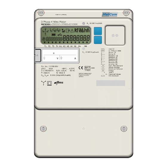
If the meter has started up, this will be indicated directly by an arrow in the display, and by the energy pulse LED, which will flash in accordance with the preset pulse constant. Figure 23: Front view of the MCS301 1 – Main seals 2 –... -
Page 133: Installation Check Using The Meter Display
In that case the power of the meter should be switched off immediately and the installation should be checked again. Otherwise the meter can be damaged after 12h. MCS301 meter - product Manual 1.25 MetCom Solutions GmbH... -
Page 134: Installation Comment
The recommendation for CT connected meters in the low voltage level is the usage of fuses in the voltage path with a maximum of 10A. Figure 24: Connection of a CT meter in the low voltage level MCS301 meter - product Manual 1.25 MetCom Solutions GmbH... -
Page 135: Type Key
(48-230V AC/DC) Wired M-Bus Master (EN 13757-2) no wired M-Bus Remark: for the direct connected meter the number of I/0 is limited to RS485 interface Wired M-Bus interface 1x S0 output MCS301 meter - product Manual 1.25 MetCom Solutions GmbH... -
Page 136: Type Key For Hw Version From V1.5 Onwards
=> no comms module support possible *3) only control inputs or S0 inputs can be selected *4) only Customer interface or Synch Bus can be used *5) other values on request MCS301 meter - product Manual 1.25 MetCom Solutions GmbH... -
Page 137: Technical Data Of The Mcs301
33 Technical data of the MCS301 Page 137 of 142 33 Technical data of the MCS301 4-wire, 3 Solutions 3 x 58/100 V … 3x63/110V; or 3 x 230/400 V; +/-20% Nominal voltage 3-wire, 2 Solutions or 3x58/100 … 3x240/415Vor 3x277/480V, -20/+15% 1(2) A;... -
Page 138: Connection Diagram
Complete connection diagram In below figures the complete connection diagram (main + auxiliary connection) is shown. The diagram is fixed under the terminal cover of every meter. Figure 33: complete connection diagram MCS301 meter - product Manual 1.25 MetCom Solutions GmbH... -
Page 139: Mains Connection Diagram
Page 139 of 142 34.2 Mains connection diagram The main connection diagram is shown in the following figures Figure 34: 4-wire meter (3 Solutions), direct connection Figure 35: 3-wire meter (2 Solutions), direct connection MCS301 meter - product Manual 1.25 MetCom Solutions GmbH... - Page 140 34 Connection diagram Page 140 of 142 Figure 36: 4-wire meter (3 Solutions) for CT standard connection Figure 37: 4-wire meter (3 Solutions) for CT- and VT- standard connection MCS301 meter - product Manual 1.25 MetCom Solutions GmbH...
- Page 141 34 Connection diagram Page 141 of 142 Figure 258: 3-wire meter (2 Solutions) for CT- and VT- standard connection (on request) Figure 39: 4-wire meter (3 Solutions) without connection of the neutral MCS301 meter - product Manual 1.25 MetCom Solutions GmbH...
- Page 142 34 Connection diagram Page 142 of 142 Figure 40: 4-wire meter (3 Solutions) without connection of the neutral MCS301 meter - product Manual 1.25 MetCom Solutions GmbH...
Need help?
Do you have a question about the MCS301 and is the answer not in the manual?
Questions and answers
lettura energia attiva del mese precedente
To read the active energy for the previous month on the Metcom Solutions MCS301 meter, follow these steps:
1. Use the Blue2Link readout and setting tool.
2. Connect to the meter via the optical or RS485 interface.
3. Access the register data using the DLMS/COSEM protocol.
4. Retrieve the required OBIS codes:
- 1-0:1.8.x.255 for positive active energy (+A).
- 1-0:2.8.x.255 for negative active energy (-A).
5. Check the load profile data or billing data for the previous month.
6. Use the log file to verify stored historical energy values.
These steps allow retrieval of active energy consumption for the previous month.
This answer is automatically generated