Table of Contents
Advertisement
Quick Links
Advertisement
Table of Contents

Related Manuals for Code Soft EVO-TM2A

Summary of Contents for Code Soft EVO-TM2A
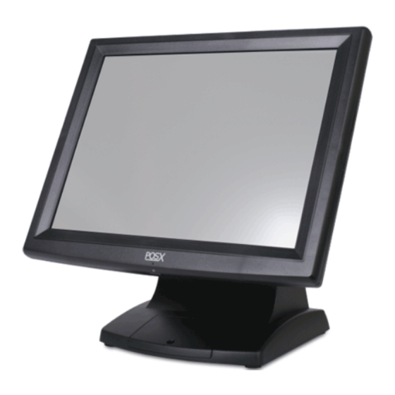
- Page 1 User Manual Revision v1.3 Dec. 2010 EVO-TM2A EVO-TM2B Touch Screen Monitor...
- Page 2 Copyright 2010 August All Rights Reserved Manual Version 1.3 Part Number: 3LMPP1300213 The information contained in this document is subject to change without notice. We make no warranty of any kind with regard to this material, including, but not limited to, the implied warranties of merchantability and fitness for a particular purpose.
- Page 3 Safety IMPORTANT SAFETY INSTRUCTIONS To disconnect the machine from the electrical Power Supply, turn off the power switch and remove the power cord plug from the wall socket. The wall socket must be easily accessible and in close proximity to the machine. Read these instructions carefully.
- Page 4 CAUTION ON LITHIUM BATTERIES There is a danger of explosion if the battery is replaced incorrectly. Replace only with the same or equivalent type recommended by the manufacturer. Discard used batteries according to the manufacturer’s instructions. LEGISLATION AND WEEE SYMBOL 2002/96/EC Waste Electrical and Electronic Equipment Directive on the treatment, collection, recycling and disposal of electric and electronic devices and their components.
- Page 5 Revision History Changes to the original user manual are listed below: Revision Date Description V1.0 Sep. 2009 Release V1.1 Oct. 2009 MB version change V1.2 Aug. 2010 MB version change V1.3 Dec. 2010 Model name change...
-
Page 6: Table Of Contents
Table Contents 1 Package Checklist ........1 Standard Items ..............1 Optional Items ..............2 2 System View..........3 Front View ................3 Rear View................4 Bottom View ................. 5 I/O View................6 3 Peripheral Installation ......7 MSR ..................7 VFD .................. -
Page 7: Package Checklist
Package Checklist Take the system unit out of the carton. Remove the unit from the carton by holding it by the foam inserts. The following contents should be found in the carton: Standard Items a. Monitor b. Driver CD c. Power Adapter (36W) d. -
Page 8: Optional Items
Optional Items a. MSR Module b. VFD Module c. Wall Mount Kit... -
Page 9: System View
System View Front View System Overview table -1 Number Component Touch Screen MSR (Optional) OSD Button for OSD menu selection From left to right button: Stand Hole for cable management... -
Page 10: Rear View
Rear View System Overview table -2 Number Component VFD Module (Optional) Stand (with cable management and power adapter bracket) Cable Outlet VFD Cover (VFD module installation location) VESA hole for stand and wall-mount kit installation... -
Page 11: Bottom View
Bottom View System Overview table -3 Number Component Easy-Service Retaining Bracket for Power Adapter Rubber feet... -
Page 12: I/O View
I/O View System Overview table -4 Number Component USB (to Device) USB IN (from PC) VGA IN COM IN COM 12V 12V IN... -
Page 13: Peripheral Installation
Peripheral Installation Components of MSR Kit: Screws Grounding Slide the MSR into the right position of the System. Fasten the screws (x2) and grounding cable (x1). -
Page 14: Vfd
Components of VFD Kit: Plastic bracket Metal Bracket Screws Unfasten the screws (x2) and slide the VFD Cover outward. ❶ ❷ Position the VFD metal bracket onto the rear side of the VFD module and fasten the screws (x4). Position the plastic bracket on the metal bracket as shown in the images above. - Page 15 Fasten the screw (x1) to attach the plastic bracket to the metal bracket and VFD module. Slide the VFD module with bracket into the VFD socket. Attach the VFD module by fastening the screws (x2) as shown. Connect the VFD’s RJ45 to the VFD Module. Connect the other end of the VFD Cable to the Touch Screen Monitor.
-
Page 16: Wall Mount Kit
Wall Mount Kit Before installing the Wall Mount Kit, please remove the stand first. (See Chapter 4-1) (Parts of Wall Mount Kit) (Location to install) a. Wall Plate b. Monitor plate VESA Wall Mount Kit includes the following: a. Wall-mount plate b. - Page 17 Mount part “a” to the wall in your desired location. Align the hooks of the monitor plate with the keyholes of the wall plate and slide the monitor into place. Tighten the thumb screw (x1).
-
Page 18: System Assembly & Disassembly
System Assembly & Disassembly Remove the System Stand Remove the screws (x2) that secure the stand to the system. Remove the screws (x4) that secure the VESA mount to the monitor. Remove the VESA bracket. -
Page 19: Replace The Power Adapter
Replace the Power Adapter Release the thumb screw to seperate the retaining metal bracket from the stand and take out the power adapter. -
Page 20: Specification
Specification Model Name EVO-TM2A EVO-TM2B AD board LCD Panel Panel Size 15" 17" Brightness 250nits 300~380nits Resolution 1024 x 768 1280 x 1024 Touch Resistive Tilt Angle 4° ~ 90° External I/O Ports 1 x USB 2.0 (Type A), 1x USB 2.0 (Type B to PC)
Need help?
Do you have a question about the EVO-TM2A and is the answer not in the manual?
Questions and answers