
Related Manuals for VERDER Carbolite Gero EVC 12/450B


Summary of Contents for VERDER Carbolite Gero EVC 12/450B
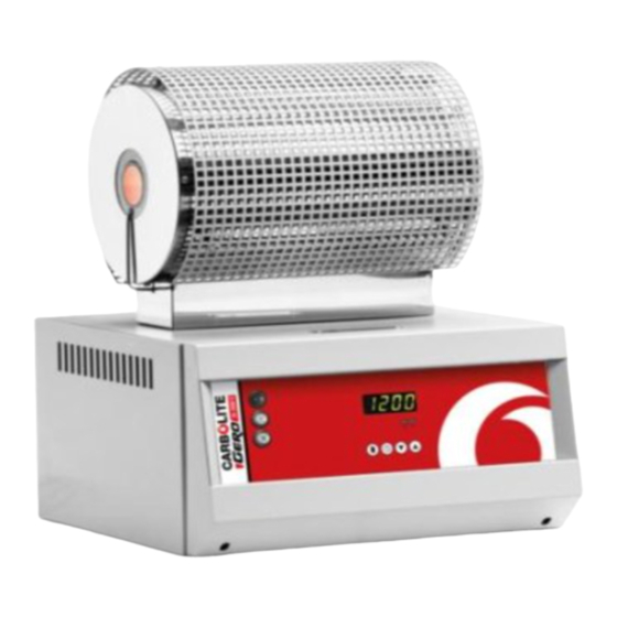
- Page 1 Installation, Operation and Maintenance Instructions 1200°C Tube Furnace (3-zone) - EVC Model: 450mm No Controller EVC 12/450B + No Controller MEN-EVC12450B-16_NOCTRL 09-07-2019...
-
Page 2: Table Of Contents
Contents This manual is for guidance on the use of the Carbolite Gero product specified on the front cover. This manual should be read thoroughly before unpacking and using the furnace or oven. The model details and serial number are shown on the back of this manual. - Page 3 Operator Safety Tube Life Pressure Gas Tightness 5.0 Maintenance General Maintenance Maintenance Schedule 5.2.1 Cleaning Calibration After-Sales Service Recommended Spare Parts and Spare Parts Kit 6.0 Repairs and Replacements Safety Warning - Disconnection from Power Supply Safety Warning - Refractory Fibre Insulation Temperature Controller Replacement Solid-state Relay Replacement Thermocouple Replacement...
-
Page 4: Symbols And Warnings
1.0 Symbols and Warnings 1.0 Symbols and Warnings Switches and Lights Instrument switch: when the instrument switch is operated the temperature control circuit is energised. Heat light: the adjacent light glows or flashes to indicate that power is being supplied to the elements. Heat switch: the switch disconnects power to the heating elements;... -
Page 5: Warning Labels
1.0 Symbols and Warnings Caution – Double Pole/Neutral Fusing Warning Labels On the front control panel there are 2 warning labels as shown in figure 1.3.1; they are numbered 7 and 8. These warnings must be followed for the safe operation of this furnace. - Page 6 1.0 Symbols and Warnings Figure 1.3.1 - Control Box layout and warning Figure 1.3.2- Back of control box showing labels. mains lead socket Index to numbered items in Figure 1.3.1 and 1.3.2 1. Electrical supply switch - switches electrical power ON and OFF to the furnace. 2.
-
Page 7: Installation
2.0 Installation 2.0 Installation If the product has been transported or stored in humid conditions it must be dried out completely before operating the furnace. Contact Carbolite Gero Service for instructions. Unpacking and Handling When unpacking or moving the product, always lift it by its base or both ends of the main body. -
Page 8: Setting Up
2.0 Installation If the product is to be used in a process which could liberate hazardous gases, then it should be installed together with a suitable fume extraction system. Ensure that the product is placed in such a way that it can be quickly switched off or disconnected from the electrical supply. - Page 9 2.0 Installation 2.3.1 Figure - Vertical tube furnace model 2.3.2 Figure - Assembling the mounted on its stand. stand. Index to numbered items in Figure 2.3.2 and Figure 2.3.3 1. Vertical stand base 2. Vertical stand upright 3. Fixing screws M6 x 16 dome cap screw 4.
- Page 10 2.0 Installation Using the tube furnace horizontally The furnace can be used either with the stand vertically as shown in 2.3.3 or horizontally as shown in 2.3.4. To use horizontally simply tip the stand over into the horizontal position making sure that the flexible conduits are not trapped beneath the frame.
- Page 11 2.0 Installation Index to numbered items in Figure 2.3.5 1. Tube furnace 2. Work tube adaptor (size dependent on work tube diameter) 3. Work tube (size diameter customer option) 4. Work tube adaptor fixing bracket 5. Fixing screws M6 x 15 6.
- Page 12 2.0 Installation Figure 2.2 - shows an exploded view of all the required parts. Figure 2.2 - shows the assembled parts as they would be used. 2.3.6 Figure - Tube support 2.3.7 Figure - Tube support assembly...
- Page 13 2.0 Installation 2.3.8 Figure - Tube support and end seal assembly 2.3.9 Figure - Tube support and end seal assembly For extra stability of the tube, repeat the assembly instructions above (as shown in figure 2.3.10...
-
Page 14: Setting Up - Without A Stand
2.0 Installation 2.3.10 Figure - View showing how to support the work tube in a vertical orientation. Setting Up - Without a Stand Any of the E-range vertical furnaces can be supplied without a stand for either wall mounting (using wall bracket order option) or installation in customer's test rig/mounting frame. - Page 15 2.0 Installation Index to numbered items in Figure 2.4.1 1. Control Box 2. Furnace Body 3. Connecting conduit between furnace and control box Fitting the Optional Insulation Plugs and Radiation Shield For optimum temperature uniformity, insulation plugs or radiation shields should be placed in the work tube ends as shown below.
-
Page 16: Electrical Connections
2.0 Installation Under no circumstances should any objects be placed on top of the product. Always ensure that any vents on the top of the product are clear of any obstruction. Always ensure all cooling vents and cooling fans (if fitted) are clear of any obstruction. -
Page 17: Temperature Controller
3.0 Temperature Controller 3.0 Temperature Controller If this product is fitted with a temperature controller, instructions are provided separately. -
Page 18: Operation
4.0 Operation 4.0 Operation Operating Cycle This product is fitted with an instrument switch which cuts off power to the control circuit. Connect the product to the electrical supply. Turn on the instrument switch to activate the temperature controllers. The controllers illuminate and go through a short test cycle. -
Page 19: 3-Zone Control Methods
4.0 Operation Explosive Materials The furnace must not be used to heat materials which could explode, or which could emit gases that could form explosive mixtures. If the safe heating of a material is dependent on its temperature, only heat these type of materials if the furnace has the optional over-temperature protection device fitted. -
Page 20: Retransmission Of Setpoint
4.0 Operation thermocouples are wired in opposition to the centre zone reference thermocouple. If the temperatures of the centre and end zones are the same then 0°C will be displayed on the end zone controllers. If the end zone temperatures are either higher or lower than the centre zone, the end zone controller will display the difference in temperature (higher = positive value, lower = negative value). -
Page 21: Independent Control
4.0 Operation To make this adjustment on other controllers, enter thelevel 2 menu of the end zone controllers (see controller operating instruction), scroll to LOC.T (local trim) and use the down buttons to enter the desired positive or negative value. This will then be added to, or subtract from, the end zone set temperature. -
Page 22: Tube Life
4.0 Operation Tube Life A ceramic work tube may crack if work pieces are inserted too quickly or at temperatures below 900 °C (when the tube is more brittle). Large work pieces should also be heated slowly to ensure that large temperature differences do not arise. - Page 23 4.0 Operation than inert gases, such as nitrogen.
-
Page 24: Maintenance
5.0 Maintenance 5.0 Maintenance General Maintenance Preventive rather than reactive maintenance is recommended. The type and frequency depends on the product use; the following are recommended. Maintenance Schedule CUSTOMER QUALIFIED PERSONNEL DANGER! ELECTRIC SHOCK. Risk of fatal injury. Only electrically qualified personnel should attempt these maintenance procedures. - Page 25 5.0 Maintenance rect positioning Seals (if fitted) Check all seals and O-rings and clamps Performance Element Circuit Electrical measurement Measure the current drawn on each Power Consumption phase / circuit Check whether the cooling fans are work- Cooling Fans (if fitted)
-
Page 26: Cleaning
5.0 Maintenance 5.2.1 Cleaning Soot deposits may form inside the furnace, depending on the process. At appropriate intervals remove these by heating as indicated in the General Operation Notes. The product's outer surface may be cleaned with a damp cloth. Do not allow water to enter the interior of the case or chamber. -
Page 27: Repairs And Replacements
6.0 Repairs and Replacements 6.0 Repairs and Replacements Safety Warning - Disconnection from Power Supply Immediately switch the product off in the event of unforeseen circumstances (e.g. large amount of smoke). Allow the product to return to room temperature before inspection. Always ensure that the product is disconnected from the electrical supply before repair work is carried out. -
Page 28: Solid-State Relay Replacement
6.0 Repairs and Replacements Solid-state Relay Replacement Disconnect the product from the power supply and remove the appropriate cover as given above. Make a note of the wire connections to the solid state relay and disconnect them. Remove the solid state relay from the base panel or aluminium plate. Replace and reconnect the solid state relay ensuring that the bottom of it has good thermal contact with the base panel or aluminium plate. -
Page 29: Fuse Replacement
6.0 Repairs and Replacements Fuse Replacement Fuses are marked on the wiring diagram with type codes, e.g. F1, F2. For more information on fuses refer to section 9.0. Depending on model and voltage, the different fuse types may or may not be fitted. If any fuse has failed, it is advisable for an electrician to check the internal circuits. -
Page 30: Fault Analysis
7.0 Fault Analysis 7.0 Fault Analysis Furnace Does Not Heat Up The HEAT The heating element Check also that the SSR is working light is ON has failed correctly The controller shows a The HEAT The thermocouple has broken or has very high temperature light is OFF a wiring fault... -
Page 31: Product Overheats
7.0 Fault Analysis Product Overheats Product only heats up The controller when the instrument shows a very high The controller is faulty switch is ON temperature The thermocouple may be The controller faulty or may have been shows a low removed out of the heating temperature chamber... -
Page 32: Wiring Diagrams
8.0 Wiring Diagrams 8.0 Wiring Diagrams WC-13-30 WC-13-31 Connections below show single phase with indirect safety switches and over- temperature control. -
Page 33: Fuses And Power Settings
9.0 Fuses and Power Settings 9.0 Fuses and Power Settings Fuses F1 - F2: Refer to the circuit diagrams. GEC Safeclip of the type shown Fitted if supply cable fitted. Internal (glass type F up to 16 A) Supply Fitted on board to some types 38 mm x 10 mm type F fitted on Fuses of EMC filter. -
Page 34: Power Settings
9.0 Fuses and Power Settings 9.2 Power Settings The power limit settings (OP.Hi) for this model is as follows. The figures represent the maximum percentage of time that controlled power is supplied to the elements. Do not attempt to "improve performance" by setting a value higher than the one from the table. -
Page 35: Specifications
10.0 Specifications 10.0 Specifications Carbolite Gero reserves the right to change the specification without notice. All models have cylindrical elements with wire mounted in the surface of the insulation material. All models can accept work tubes up to a maximum outside diameter of 60 mm. All models have a maximum operation temperature of 1200°C (1100°C continuous). -
Page 36: Furnace Drying Out Process
10.0 Specifications Furnace drying out process Step 1. Before the furnace is connected to the electrical supply, remove the back panel and check for signs of moisture on the electrical circuits. If visible signs of moisture are present then allow it to dry out in ambient temperature for at least 24 hours. If the problem persists ensure that the furnace is isolated and contact Carbolite Gero Service for more information. - Page 37 Notes Service Record Engineer Name Date Record of Work...
- Page 38 The products covered in this manual are only a small part of the wide range of ovens, chamber furnaces and tube furnaces manufactured by Carbolite Gero for laboratory and industrial use. For further details of our standard or custom built products please contact us at the address below, or ask your nearest stockist.
Need help?
Do you have a question about the Carbolite Gero EVC 12/450B and is the answer not in the manual?
Questions and answers