
Related Manuals for Radio Engineering Industries HD6-600


Summary of Contents for Radio Engineering Industries HD6-600
- Page 1 HD6-600 Mobile DVR Radio Engineering Industries HD6-600 Mobile Digital Video Recorders Hardware User Manual Hardware Installation Manual Page 1 of 67 Radio Engineering Industries, Inc. 640611 – 8/17/22...
-
Page 2: Table Of Contents
HD6-600 Mobile DVR Table of Contents List of Figures ........................4 Introduction ........................6 Features ..........................6 Specifications ........................7 System Overview ....................... 9 Front and Back Panels ......................10 Live View........................11 Initial Set Up ......................... 11 Removable HDD and SD Card ..................12 DVR Loading and Unloading .................. - Page 3 HD6-600 Mobile DVR Setup Menu ........................31 System Setup Menu ......................32 ID Menu ..........................32 Time & Date Menu ....................... 33 Start Up Menu........................34 Faults Menu .......................... 35 Password Menu ........................36 Video Setup .......................... 37 Camera Menu........................38 IP and Port Setup Menu ......................
-
Page 4: List Of Figures
Alarm ............................ 65 FCC Statement ........................ 67 List of Figures Figure 1: HD6-600 MDVR System Diagram ..............9 Figure 2: Front Panel Layout .................... 10 Figure 3: Rear Panel Layout ..................... 11 Figure 4: Removable Hard Drive Module ................ 12 Figure 5: Removable SD Card .................. - Page 5 HD6-600 Mobile DVR Figure 39: Motion Setup ....................43 Figure 40: Motion Setup - Set Grid .................. 44 Figure 41: OSD Setup ....................... 45 Figure 42: Input Setup ...................... 45 Figure 43: Speed Setup ..................... 46 Figure 44: Inputs Setup ..................... 47 Figure 45: Input Setup - Custom ..................
-
Page 6: Introduction
1-877-726-4617 Toll Free 1-402-339-2200 The HD6-600 is a cost effective, embedded mobile DVR solution supporting up to 4 analog camera inputs and 2 IP camera inputs. This system features a unique compact rugged design engineered to meet the demands of harsh mobile environments. The HD6 mobile DVR features the latest technologies including H.264/MPEG-4 Advanced Video... -
Page 7: Specifications
HD6-600 Mobile DVR Specifications Power: 8 to 32 Volts DC, <2A operating (excludes cameras, accessories) Dimensions: Without brackets: 7.4" x 3.2" x 9.5"; with brackets: 9.1" x 4.0" x 9.5" (max) Weight: 8.6 lbs. (3.90 kg) with mounting brackets Standby Current: < 2mA Operating Temperature: -40°-+160°F continuous operation... - Page 8 HD6-600 Mobile DVR Inputs/Outputs USB ports: Two front panel USB ports for mouse and video backup, firmware update, configuration, and debugging (log files, etc.) WAN Ports: Rear panel WAN (Ethernet) port for connection to external 3G/4G cellular router and for connection to REI and non-REI in-vehicle systems LAN Ports (IPC, etc.): Front panel LAN port for local DVR configuration, camera...
-
Page 9: System Overview
HD6-600 Mobile DVR System Overview Figure 1: HD6-600 MDVR System Diagram Page 9 of 67 Radio Engineering Industries, Inc. 640611 – 8/17/22... -
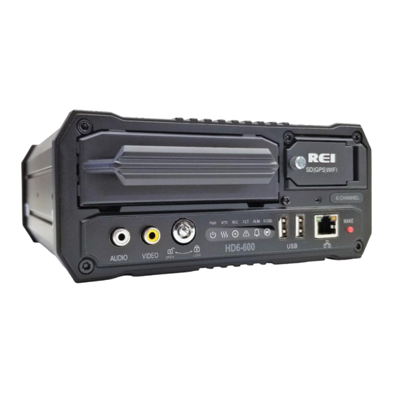
Page 10: Front And Back Panels
HD6-600 Mobile DVR Front and Back Panels Figure 2: Front Panel Layout Page 10 of 67 Radio Engineering Industries, Inc. 640611 – 8/17/22... -
Page 11: Live View
Initial Set Up The HD6-600 Mobile DVR system will operate prior to any user setup with the default settings. However, it may not show the correct time and date (factory set to Central Standard Time). To set the correct date and time, and program the system operation to your requirements, refer to the Menu Configuration section of this manual. -
Page 12: Removable Hdd And Sd Card
Removing HDD: Turn the HDD key to the unlocked and off position. Grab the handle on the HDD and carefully pull it out. Note: The HD6-600 Mobile DVR will function even in the absence of an HDD. Without HDD, DVR will power on and allow the user to configure the settings, but it will not record any videos unless the user loads the HDD and locks the HDD key. -
Page 13: Sd Card Loading And Unloading
HD6-600 Mobile DVR SD Card Loading and Unloading Inserting SD Card: Open the access door and insert the SD card all the way in until it locks in place. Removing SD Card: Push on the SD card all the way in, then release to eject the SD card. -
Page 14: Hdd Record Times
Figure 6: Estimator for HDD Record Times (HD5 shown) Long Term Storage The HD6-600 Mobile DVR system draws a small amount of current in stand-by mode. If the systems are installed, but not used for an extended length of time (i.e., longer than two weeks) it is recommended that the power be disconnected from the DVR to avoid draining the vehicle battery. -
Page 15: Installation
HD6-600 Mobile DVR Installation WARNING DISCONNECT VEHICLE BATTERY VOLTAGE BEFORE INSTALLING System WIRING WARNING DISCONNECT POWER TO THE DVR BEFORE JUMP STARTING VEHICLE Figure 7: System Wiring - Power and Camera Cables Page 15 of 67 Radio Engineering Industries, Inc. -
Page 16: External Record Indicator / Event Mark Button Harness
HD6-600 Mobile DVR External Record Indicator / Event Mark Button Harness Figure 8: External Record Indicator/Event Mark Button Harness Connection The optional external record indicator / event mark button harnesses (Panic Button) are available with two different types of switches, OEM, and aftermarket. The OEM switch is rectangular and fits into a standard size dashboard knockout. -
Page 17: Gps Antenna Module Harness
HD6-600 Mobile DVR GPS Antenna Module Harness Figure 9: GPS Antenna Module Harness Connection The optional DVR GPS antenna module harness plugs into the back of the DVR. This module will track up to 12 satellites at a time while providing one-second navigation updates at low power consumption. -
Page 18: Vehicle Sensor Options Harness
HD6-600 Mobile DVR Vehicle Sensor Options Harness Figure 10: Vehicle Sensor Options Harness Connection The Vehicle Sensor Options harness connects to various locations in the vehicle to provide on-screen information regarding vehicle performance. Vehicles have different sets of signals that can be monitored. Two levels of pre-defined on-screen displays are available to the installer: SCHOOL BUS and TRANSIT. -
Page 19: Vehicle Sensor Options Harness Vehicle Connections
HD6-600 Mobile DVR Vehicle Sensor Options Harness Vehicle Connections (Shown as School Bus) WIRE COLOR WIRE DESCRIPTION BLACK RED WARNING LAMP BROWN YELLOW WARNING LAMP LEFT TURN SIGNAL ORANGE RIGHT TURN SIGNAL YELLOW STOP ARM GREEN BRAKES BLUE FRONT DOOR... -
Page 20: On-Screen Information With Vehicle Sensor Options Harness
HD6-600 Mobile DVR On-Screen Information with Vehicle Sensor Options Harness The HD6-600 Mobile DVR Surveillance system, when equipped with the HD6-600 Mobile DVR Option Harness, will display information on-screen in the Installers Mode when the monitored switches on the vehicle are activated and signals are applied to the monitored sensors. -
Page 21: Accelerometer Module Harness
HD6-600 Mobile DVR Accelerometer Module Harness Figure 11: Accelerometer Module Harness Connection The optional external Accelerometer, or Inertia Sensor, must be hard mounted to the vehicle floor, frame, or some other non-dampened part of the vehicle. If external dampening is used for the DVR, hard mounting the accelerometer will prevent the accelerometer readings from being compromised. -
Page 22: Physical Mounting Requirements
HD6-600 Mobile DVR Physical Mounting Requirements L Bracket Mounting The DVR has two L-brackets along the side of the unit to allow easy mounting. This type of installation is recommended for vehicles that have a secured compartment, such as a radio box, where the DVR is protected from tampering. -
Page 23: Security Cover Mounting
HD6-600 Mobile DVR Figure 14: DVR Dimensions Security Cover Mounting There may be installations that require the front and back of the DVR to be enclosed in a protective enclosure. Security covers can be installed to protect the front and back of the DVR. -
Page 24: Camera Placement
Check local, state, and federal guidelines as to modification of the existing structures within the vehicle. Camera Placement The HD6-600 Mobile DVR cameras can be mounted anywhere in the vehicle, unless the mount is unstable, or the cameras vibrate excessively. Use outdoor cameras for exterior placement. -
Page 25: Playback Options
HD6-600 Mobile DVR Playback Options The various ways to view the recorded videos: through the TV Video Outputs, through the Removable Hard Drive Module, SD card, through the PC Network Connection, and with a mobile device such as a cell phone or a tablet. - Page 26 HD6-600 Mobile DVR Default DVR LAN Settings: IP Address: 192.168.200.200 Net Mask: 255.255.255.0 Password: 10231981 To access the DVR from a computer, the TCP/IP network settings on the computer need to be configured to match the settings in the DVR to insure both devices are in the same network.
-
Page 27: Rei Toolkit
HD6-600 Mobile DVR Once the computer is set up, open Internet Explorer and enter the IP address of the DVR in the web address bar. In some cases, the web browser may display a prompt requesting the installation of add-on software in order to access the DVR Web UI. Before displaying the Web UI, the web browser will display a prompt requesting the username and password for the DVR. -
Page 28: Connecting To An Android
HD6-600 Mobile DVR Connecting to an Android™ To connect to the REI Dongle, go into ‘Settings’ and choose ‘Network & Internet,’ and then ‘Wi-Fi.’ From the list of Wi-Fi links, locate the appropriate Wi-Fi link and attempt to make a Wi-Fi connection. -
Page 29: Logging In
HD6-600 Mobile DVR Figure 17: Initial DVR Window Logging In Touch the name of the DVR, (REI-009 for example) and a Login prompt will appear as shown below. Figure 18: Login Window By default, the initial password is 10231981. The Remember box could already be checked. -
Page 30: Sd Card Function
HD6-600 Mobile DVR SD Card Function On the side of the REI Toolkit Dongle is a slot that serves as a Secure Digital (SD) card reader. When the red SD lamp is active, it indicates the SD card has been successfully loaded in the SD card slot and is operational. -
Page 31: Menu Configuration
HD6-600 Mobile DVR Menu Configuration Main Menu Page Figure 20: Main Menu The DVR Main Menu can be accessed by using any standard USB mouse and video monitor. For more convenient usage, REI offers its hand-held USB trackball mouse; P/N 690816. -
Page 32: System Setup Menu
HD6-600 Mobile DVR The Setup section of the Menu is subdivided into four main categories listed in the left column of the window: System, Video, Input Setup, and Network. System Setup Menu Figure 22: System Setup Options System: The System section of the Setup Sub-Menu is sub-divided into five subcategories: ID, Time &... -
Page 33: Time & Date Menu
HD6-600 Mobile DVR Time & Date Menu Figure 24: Time & Date Time & Date menu allows the user to configure options for setting the Date and the Time. All REI DVRs have high accuracy, extended temperature range real time clocks with 10- year internal battery backup for consistent and reliable time keeping over the life of the DVR system. -
Page 34: Start Up Menu
HD6-600 Mobile DVR Figure 25: Custom DST Triggers Start Up Menu Figure 26: Start Up Menu in Ignition Mode The Start Up Menu allows the user to determine when the DVR starts/stops recording video and how long the DVR stays on after shutting off the ignition. -
Page 35: Faults Menu
HD6-600 Mobile DVR Figure 27: Record Schedule Menu Include Mini-Player Into HDD: Check this box to enable the mini-player. Faults Menu Figure 28: Faults The Audio/Visual Setup menu enables the DVR to display an Audio/Visual alert if the DVR is experiencing an alert condition. -
Page 36: Password Menu
HD6-600 Mobile DVR System Fault: DVR experiencing problems such as voltage too high or too low. Fault Beeper: The types of alerts/faults that will cause the fault beeper to activate. Blind Camera: Camera blocked by objects. Video Loss: DVR not receiving camera video. -
Page 37: Video Setup
HD6-600 Mobile DVR Video Setup Figure 30: Video Setup Video: The Video setup section of the menu is sub-divided into seven main categories; Camera, Alarm, SD, Sub-Stream, Image, Motion and OSD. Under Video, the channels can be enabled or disabled, and the camera configuration can be set up. -
Page 38: Camera Menu
HD6-600 Mobile DVR Camera Menu Figure 31: Camera – Camera Setup The Camera Setup subsection of the Video Setup section allows the user to change all the related camera record settings, such as number of cameras, resolution, frame rate, etc. -
Page 39: Ip And Port Setup Menu
HD6-600 Mobile DVR The Camera Configuration setting allows a customized record setting to each individual camera. Channel: Enables channel to display on screen in the Channel Name cell when selected. Note: When Live is selected, but Rec is not selected the DVR only displays that camera video but does not record it. -
Page 40: Network Setup Menu
HD6-600 Mobile DVR Network Setup Menu Figure 34: Individual Channel Network Setup Channel: The number of the channel being setup Protocol Type: REI IP address: Internet protocol address of the channel being setup Port: Port identification for the channel User name: Used to enter camera configuration menu... -
Page 41: Sd Menu
HD6-600 Mobile DVR Pre-Alarm Video to include with Alarm: Range is set between 0-300 seconds. Post-Alarm Video to Include with Alarm: Range is set between 10-1800 seconds. SD Menu Figure 36: SD Setup SD Record Mode: Select Alarm or Mirror Alarm: Records only alarm video to the SD card. -
Page 42: Sub-Stream Menu
HD6-600 Mobile DVR Sub-Stream Menu Figure 37: Sub-Stream Setup Resolution: The resolution of the sub-stream (fixed at CIF). Frame Rate: The frame rate of the sub-stream. Ranges between 1 and 30. Quality: The quality (bit rate) of the sub-stream. Ranges between 10% and 100% of target bit rate. -
Page 43: Motion Menu
HD6-600 Mobile DVR The Image function allows the user to adjust the camera signal to improve video quality. Individual channels can be adjusted to suit different cameras. The result is visible on the right side of the screen. Channel: The channel that needs adjustment. -
Page 44: Figure 40: Motion Setup - Set Grid
HD6-600 Mobile DVR Motion Setup menu controls the video motion detection system of the DVR. The user can enable camera motion detection individually. The system can be set to trigger a motion detection alarm. Sensitivity and area settings are adjustable for each camera. -
Page 45: Osd Menu
HD6-600 Mobile DVR OSD Menu Figure 41: OSD Setup OSD (On Screen Display): Divided into three subcategories Record, Playback, and Live. Record: Selected data types will be recorded permanently over video. Playback: Selected data types will be displayed during playback via monitor/mouse. -
Page 46: Speed Menu
HD6-600 Mobile DVR Speed Menu Figure 43: Speed Setup Speed Setup Menu contains settings to change the speedometer source, speed unit, speedometer calibration, and high-speed alarm. Speed Source: The DVR speed source; GPS, J1939#1 and J1939#2. Speed Units: MPH and KMH speed units. -
Page 47: Inputs Menu
HD6-600 Mobile DVR Inputs Menu Figure 44: Inputs Setup The Inputs Setup shows all the available inputs on the DVR. Each signal can be renamed, adjusted to active high/low, and set to trigger alarms when activated. There are two preset vehicle types to choose from: School Bus and Transit. -
Page 48: Accel Menu
HD6-600 Mobile DVR Active: State which is considered active (low/ground or high/+ volt). Alarm: Triggers alarm when the input is in the active state. Presets: Preload input names and abbreviations for School Bus and Transit Bus. Accel Menu Figure 46: Accelerometer Setup The Accel Menu gives user options to configure the accelerometer. -
Page 49: Gps Port Menu
HD6-600 Mobile DVR Figure 47: Accel Alarm Figure 48: Accelerometer Threshold GPS Port Menu Figure 49: GPS Port Page 49 of 67 Radio Engineering Industries, Inc. 640611 – 8/17/22... - Page 50 HD6-600 Mobile DVR Mode: Set the mode of the GPS port Status Out or External GPS (input). Baud Rate: Baud Rate of the GPS Port (4800 – 115200). The default setting for the REI GPS Module is 38400. Page 50 of 67 Radio Engineering Industries, Inc.
-
Page 51: Network Setup
HD6-600 Mobile DVR Network Setup Figure 50: Network Setup Network: The user can configure the DVR to connect to the network. It has inputs for WAN/LAN settings, server, WIFI, Cellular connections and Routes. WAN/LAN Setup Figure 51: General Network Setup WAN/LAN setup is where the user sets up the network configuration if using the Ethernet port located on the front and back of the DVR. -
Page 52: Server
HD6-600 Mobile DVR IP Address: WAN or LAN IP Address. Netmask: LAN Netmask. Auto DNS: Use DHCP-provided IP address for DNS if checked. Primary DNS: Primary DNS Server IP address for WAN Secondary DNS: Secondary DNS Server IP address for WAN Contact your IT specialists for assistance configuring this page. -
Page 53: Wifi Menu
HD6-600 Mobile DVR WIFI Menu Figure 53: WIFI Setup The Wireless Network settings allow the DVR to have a wireless connection. It also supports Auto IP detection for easy set up. SSID: SSID of the access point of the WIFI network. -
Page 54: Cellular
HD6-600 Mobile DVR Cellular Figure 54: Cellular Setup Configuration for internal cellular card. Applicable to cellular models only. Contact your IT specialists for assistance configuring this page. Route Figure 55: Route Setup Page 54 of 67 Radio Engineering Industries, Inc. -
Page 55: Firewall
HD6-600 Mobile DVR Configuration of default gateway and static routing. Contact your IT specialists for assistance configuring this page. Firewall Figure 56: Firewall Setup Enable Firewall: Select this check box to utilize firewall protection for selected IP/URL addresses. Enable: Select this check box to enable firewall protection for the corresponding Allowed IP Addresses/URLs. -
Page 56: Info
HD6-600 Mobile DVR Info Figure 57: Info Menu Info: Display only tab that displays status information of channels, active alarms, system information, WAN/Cell and WIFI connections, the system firmware versions, and logs. Displayed data is displayed across eight subsections: Camera, Inputs, Alarms, System, WAN/Cell, WIFI, Versions, and Logs. -
Page 57: Alarms
HD6-600 Mobile DVR GPS: Current GPS coordinates. Data: LAT/LON/HEAD J1939: The Current status of the J1939 interface. ALPR: The Current status of the optional ALPR 2.0 Pod. Alarms Figure 60: Alarms Tab Active Alarms: Alarms that are currently occurring. System Figure 61: System Tab Active Faults: Faults that are actively occurred. -
Page 58: Wan/Cell
HD6-600 Mobile DVR WAN/Cell Figure 62: WAN/Cell Tab WAN: Current IP address, Gateway, etc. of the WAN interface. Cell: Current IP address, Gateway, etc. of the internal cellular interface. Signal Strength (RSSI): Current signal strength of the internal cellular interface. -
Page 59: Versions
HD6-600 Mobile DVR Versions Figure 64: Versions Tab Version of the Main/MCU Firmware, Serial Number, System ID, Model, MCU, and ALPR version. Logs Access to the system or fault logs by date. Figure 65: Fault Logs Tab Page 59 of 67 Radio Engineering Industries, Inc. -
Page 60: Advanced
HD6-600 Mobile DVR Figure 66: Logs – Search Result System Logs Advanced For internal use only. Figure 67: Advanced Tab Page 60 of 67 Radio Engineering Industries, Inc. 640611 – 8/17/22... -
Page 61: Server
HD6-600 Mobile DVR Server Figure 68: Server Tab UID: User identification. Server: Server identification. Exchange: Details about the communication between the server and the DVR. Queue: The identification of the user currently in the queue. Last Comm: The most recent communication between the DVR and the server. -
Page 62: Config Menu
HD6-600 Mobile DVR Config Menu Figure 70: Export Configuration Click Export to save the configuration to your PC. Click Browse to select a previously saved configuration file from a location on your PC, click Import to apply the saved configuration. Note: Network settings and system ID will not be overwritten by this function. -
Page 63: Storage
HD6-600 Mobile DVR Storage Figure 72: Storage Tab Format/Clear HDD: Format/clear (erase) the HDD. Format/Clear SD: Format/clear (erase) the SD. Format/Clear USB: Format/clear (erase) the USB media. Live Figure 73: Live Menu Live: Allows the user to view any or all cameras live. -
Page 64: Settings Button
HD6-600 Mobile DVR Figure 75: Sample Info Data Table Settings button Click this button to exit Live View and return to the Setup menu. Channel Selection Figure 76: Channel Selection Buttons Select individual channels for Live View. Play Back Figure 77: Playback Menu Playback: Videos recorded on the HDD can be fully accessed from the Play Back menu. -
Page 65: Video (Time/Date Search)
HD6-600 Mobile DVR Video (Time/Date Search) Figure 78: Video Tab - Time/Date Search for Date The Time/Date Search function gives the user the ability to search videos by selecting the Time and Date. The screen shows a calendar that contains videos. - Page 66 HD6-600 Mobile DVR The Alarm Search function gives the user the ability to search alarms from a list. The screen shows a list of available alarms. Select the video storage device (HDD or SD), month, and year of the desired alarm.
-
Page 67: Fcc Statement
HD6-600 Mobile DVR FCC Statement Changes or modifications not expressly approved by the party responsible for compliance could void the user's authority to operate the equipment. This equipment has been tested and found to comply with the limits for a Class B digital device, pursuant to Part 15 of the FCC Rules.
Need help?
Do you have a question about the HD6-600 and is the answer not in the manual?
Questions and answers