
Subscribe to Our Youtube Channel
Related Manuals for Radio Engineering Industries HD5-1200


Summary of Contents for Radio Engineering Industries HD5-1200
- Page 1 HD5 Series Mobile DVR Radio Engineering Industries HD5 Series Mobile Digital Video Recorders Hardware User Manual Hardware Installation Manual Page 1 of 59 Radio Engineering Industries, Inc. 640510 -- Rev A – 8/29/17...
-
Page 2: Table Of Contents
Start Up Menu........................31 Faults Menu .......................... 32 Password Menu ........................33 Video Setup .......................... 34 Camera Menu........................35 IP and Port Setup Menu ......................36 Page 2 of 59 Radio Engineering Industries, Inc. 640510 -- Rev A – 8/29/17... - Page 3 Settings button ........................56 Channel Selection ......................... 57 Play Back ........................57 Video ( ..........................57 Time/Date Search) ........................ 57 Alarm ............................ 58 FCC Statement ........................ 59 Page 3 of 59 Radio Engineering Industries, Inc. 640510 -- Rev A – 8/29/17...
-
Page 4: List Of Figures
Figure 40: Speed Setup ..................... 42 Figure 41: Inputs Setup ..................... 43 Figure 42: Input Setup - Custom ..................44 Figure 43: Accelerometer Setup ..................45 Page 4 of 59 Radio Engineering Industries, Inc. 640510 -- Rev A – 8/29/17... - Page 5 Figure 70: Playback Menu ....................57 Figure 71: Video Tab - Time/Date Search for Date ............57 Figure 72: Alarm Tab - Alarm Search ................58 Page 5 of 59 Radio Engineering Industries, Inc. 640510 -- Rev A – 8/29/17...
-
Page 6: Introduction
● Up to 2TB Hard Drive or optional Solid State Hard Drive ● Up to 256GB SD Card (optional) ● Optional Lockbox ● Extruded aluminum chassis ● Fanless design Page 6 of 59 Radio Engineering Industries, Inc. 640510 -- Rev A – 8/29/17... -
Page 7: Specifications
WIFI (internal): Optional 802.11a/b/g/n 2.4Ghz/5Ghz Wi-Fi (Wi-Fi models only) Cellular (internal): Optional 3G/4G modem for cellular connectivity GPS (internal): Optional internal or external GPS receiver Page 7 of 59 Radio Engineering Industries, Inc. 640510 -- Rev A – 8/29/17... - Page 8 GPS/Status Port (RS232): Optional external (RS232) GPS receiver Optional GPS/Status output (RS232) for interface to third-party AVL systems Sensor Inputs: Eight sensor inputs for detection of vehicle signals (brakes, turn signals, etc.) Page 8 of 59 Radio Engineering Industries, Inc. 640510 -- Rev A – 8/29/17...
-
Page 9: System Overview
HD5 Series Mobile DVR System Overview Figure 1: HD5 Series MDVR System Diagram Page 9 of 59 Radio Engineering Industries, Inc. 640510 -- Rev A – 8/29/17... -
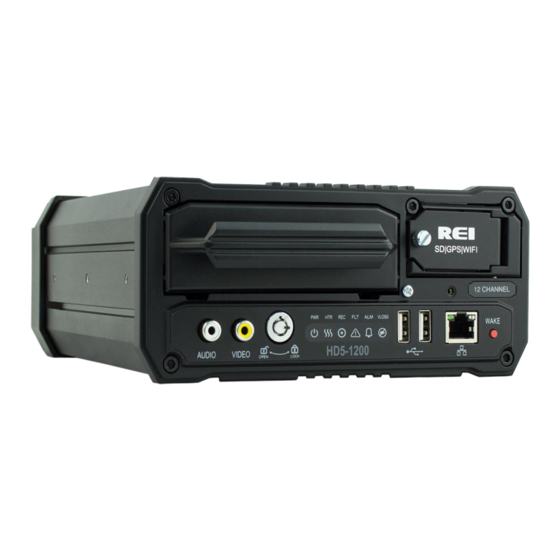
Page 10: Figure 2: Front Panel Layout
HD5 Series Mobile DVR Front and Back Panels Figure 2: Front Panel Layout Page 10 of 59 Radio Engineering Industries, Inc. 640510 -- Rev A – 8/29/17... -
Page 11: Live View
When accessing the menu, it is necessary to connect a video monitor to the video jack on the front or back of the unit. REI recommends using its battery-powered color LCD monitor P/N 750207. Page 11 of 59 Radio Engineering Industries, Inc. 640510 -- Rev A – 8/29/17... -
Page 12: Removable Hdd And Sd Card
HDD. Without HDD, DVR will power on and allow the user to configure the settings, but it will not record any videos unless the user loads the HDD and locks the HDD key. Figure 4: Removable Hard Drive Module Page 12 of 59 Radio Engineering Industries, Inc. 640510 -- Rev A – 8/29/17... -
Page 13: Sd Card Loading And Unloading
Removing SD Card: Push on the SD card all the way in, then release to eject the SD card. Figure 5: Removable SD Card Page 13 of 59 Radio Engineering Industries, Inc. 640510 -- Rev A – 8/29/17... -
Page 14: Hdd Record Times
The DVR internal clock will hold the time and date for up to 10 years sitting on a shelf, and the daylight-saving time functions will resume upon re-initialization when power is applied. Page 14 of 59 Radio Engineering Industries, Inc. 640510 -- Rev A – 8/29/17... -
Page 15: Installation
DISCONNECT VEHICLE BATTERY VOLTAGE BEFORE INSTALLING System WIRING WARNING DISCONNECT POWER TO THE DVR BEFORE JUMP STARTING VEHICLE Figure 7: System Wiring - Power and Camera Cables Page 15 of 59 Radio Engineering Industries, Inc. 640510 -- Rev A – 8/29/17... -
Page 16: External Record Indicator / Event Mark Button Harness
The aftermarket switch is round, for easier installation in vehicles without spare switch knockouts. Both styles of switches plug into the same port on the back of the DVR. Page 16 of 59 Radio Engineering Industries, Inc. 640510 -- Rev A – 8/29/17... -
Page 17: Gps Antenna Module Harness
Wi-Fi network, it could be more cost effective to use the combination Wi- Fi/GPS antenna that comes with the higher end DVRs. Page 17 of 59 Radio Engineering Industries, Inc. 640510 -- Rev A – 8/29/17... -
Page 18: Vehicle Sensor Options Harness
Warning lamp operation (de-acceleration lights) wheelchair lifts, • Brake activation inertia sensors, etc. • Front door switch operation • Back door switch operation • Optional point with Auxiliary Page 18 of 59 Radio Engineering Industries, Inc. 640510 -- Rev A – 8/29/17... -
Page 19: Vehicle Sensor Options Harness Vehicle Connections
Connect the RED and ORANGE wires to the left and right turn signal lamps. Front and Back Doors Connect the BLUE and VIOLET wires to the switched side of the door switches. Page 19 of 59 Radio Engineering Industries, Inc. 640510 -- Rev A – 8/29/17... -
Page 20: On-Screen Information With Vehicle Sensor Options Harness
RIGHT TURN SIGNAL On FRONT DOOR OPEN REAR DOOR OPEN SPEEDOMETER XX MPH (SEE NOTE 1) NOTE 1: The XXs represent the vehicle speed (i.e. 35). Page 20 of 59 Radio Engineering Industries, Inc. 640510 -- Rev A – 8/29/17... -
Page 21: Accelerometer Module Harness
After the device has been properly aligned, the Accelerometer Module must be calibrated. Figure 12: 3 Axis Inertia Sensor Directions Page 21 of 59 Radio Engineering Industries, Inc. 640510 -- Rev A – 8/29/17... -
Page 22: Physical Mounting Requirements
DVR is protected from tampering. Figure 13: L Bracket Mounting Figure 14: DVR Dimensions Page 22 of 59 Radio Engineering Industries, Inc. 640510 -- Rev A – 8/29/17... -
Page 23: Security Cover Mounting
The HD5 Series Mobile DVR cameras can be mounted anywhere in the vehicle, unless the mount is unstable or the cameras vibrate excessively. Use outdoor cameras for exterior placement. Page 23 of 59 Radio Engineering Industries, Inc. 640510 -- Rev A – 8/29/17... -
Page 24: System Start-Up
DVR will stay active after any off delay expires for network access to the hard drive, but will not record any new video in this mode. Page 24 of 59 Radio Engineering Industries, Inc. 640510 -- Rev A – 8/29/17... -
Page 25: Playback Options
Using the REI VMS PC Software, the user can access the files by connecting the computer to the DVR Front Panel Ethernet port, as shown below. Figure 16: Connecting to the DVR with a Computer through the Ethernet Connection Page 25 of 59 Radio Engineering Industries, Inc. 640510 -- Rev A – 8/29/17... - Page 26 IP Address: 192.168.200.x (x being 1-255 but different from DVR IP address) Net Mask: 255.255.255.0 (DVR Net Mask) Gateway: 192.168.200.254 (DVR Gateway) - optional Page 26 of 59 Radio Engineering Industries, Inc. 640510 -- Rev A – 8/29/17...
- Page 27 DVR. After entering the username and password, the web browser will open the Web UI. Refer to the Web UI section for more information. Page 27 of 59 Radio Engineering Industries, Inc. 640510 -- Rev A – 8/29/17...
-
Page 28: Menu Configuration
690816. The user can access recorded videos and customize the settings on the DVR. The Main Menu is comprised of five user tabs: Setup, Info, Maintenance, Live, and Playback. Setup Menu Figure 18: Setup Menu Page 28 of 59 Radio Engineering Industries, Inc. 640510 -- Rev A – 8/29/17... -
Page 29: System Setup Menu
Vehicle: Allows custom information to identify the DVRs, such as bus number. Company: Allows the user to enter company name of the bus service. Driver: Allows user to enter a driver’s name. Page 29 of 59 Radio Engineering Industries, Inc. 640510 -- Rev A – 8/29/17... -
Page 30: Time & Date Menu
When the DST Mode is set to ‘On-Manual’, the Daylight-Saving Time triggers can be changed to any of the first, second, third, fourth, or last week of any month, not overlapping. Page 30 of 59 Radio Engineering Industries, Inc. 640510 -- Rev A – 8/29/17... -
Page 31: Start Up Menu
Record Schedule: The days and times the DVR will turn on and record automatically in any schedule mode. Download Schedule: The days and times the DVR will turn on and not record to allow further downloading of video. Page 31 of 59 Radio Engineering Industries, Inc. 640510 -- Rev A – 8/29/17... -
Page 32: Faults Menu
System Fault: DVR experiencing problems such as voltage too high or too low. Fault Beeper: The types of alerts/faults that will cause the fault beeper to activate. Blind Camera: Camera blocked by objects. Page 32 of 59 Radio Engineering Industries, Inc. 640510 -- Rev A – 8/29/17... -
Page 33: Password Menu
Local: Password required when Require Local Password is set to ‘On.’ Remote: Password required for access to the DVR-hosted configuration menu webpages. Page 33 of 59 Radio Engineering Industries, Inc. 640510 -- Rev A – 8/29/17... -
Page 34: Video Setup
SD card for alarms, configure the sub-stream settings, and change the settings for the image. Users can also setup motion detect and motion alarms and configure the OSD. Page 34 of 59 Radio Engineering Industries, Inc. 640510 -- Rev A – 8/29/17... -
Page 35: Camera Menu
Record Time: The amount of time the HDD can record under the current camera setup. Resource FR/AFR/IPC/SD: Non-alarm and Alarm Frame rate percentage at current camera setup. Figure 29: Custom Record Settings Page 35 of 59 Radio Engineering Industries, Inc. 640510 -- Rev A – 8/29/17... -
Page 36: Ip And Port Setup Menu
Blind Sensitivity: User can choose between 1 – LO and up to 5 – HI. Copy To: Select the cameras to copy the settings to and click Copy. IP and Port Setup Menu Figure 30: IPC Setup Pop-up Window Page 36 of 59 Radio Engineering Industries, Inc. 640510 -- Rev A – 8/29/17... -
Page 37: Network Setup Menu
For additional information about IP camera configuration, refer to the HD5 Series Models section of the REI Customer Support Site by clicking on the following link - http://www.radioeng.info/ Alarm Menu Figure 32: Alarm Setup Page 37 of 59 Radio Engineering Industries, Inc. 640510 -- Rev A – 8/29/17... -
Page 38: Sd Menu
Main: Record high quality stream per the camera settings in Setup/Camera menu. Sub: Record smaller stream per the settings in the Setup/Sub-Stream menu. Channel Enable: Select the cameras to record to the SD card. Page 38 of 59 Radio Engineering Industries, Inc. 640510 -- Rev A – 8/29/17... -
Page 39: Sub-Stream Menu
Image allows the user to adjust the camera signal to improve video quality. Each channel can be adjusted individually to suit different cameras. The result can be viewed on the right side of the screen. Page 39 of 59 Radio Engineering Industries, Inc. 640510 -- Rev A – 8/29/17... -
Page 40: Motion Menu
Select 1, 2, 4, 8, 16, 32, or 64. Trigger: Input that must be active to enable motion detection (INPUT 1-8, NONE equals always enabled). Clear: Click to clear detection area. Page 40 of 59 Radio Engineering Industries, Inc. 640510 -- Rev A – 8/29/17... -
Page 41: Osd Menu
Figure 38: OSD Setup OSD (On Screen Display): Divided into three subcategories Record, Playback, and Live. Record: Selected data types will be recorded permanently over video. Page 41 of 59 Radio Engineering Industries, Inc. 640510 -- Rev A – 8/29/17... -
Page 42: Input Setup
Speed Setup Menu contains settings to change the speedometer source, speed unit, speedometer calibration, and high-speed alarm. Speed Source: The DVR speed source; GPS, J1939#1, and J1939#2. Page 42 of 59 Radio Engineering Industries, Inc. 640510 -- Rev A – 8/29/17... -
Page 43: Inputs Menu
There are two preset vehicle types to choose from: School Bus and Transit. When set to custom, each channel can have its own name and OSD abbreviation. Page 43 of 59 Radio Engineering Industries, Inc. 640510 -- Rev A – 8/29/17... -
Page 44: Figure 42: Input Setup - Custom
Active: State which is considered active (low/ground or high/+ volt). Alarm: Triggers alarm when the input is in the active state. Presets: Preload input names and abbreviations for School Bus and Transit Bus. Page 44 of 59 Radio Engineering Industries, Inc. 640510 -- Rev A – 8/29/17... -
Page 45: Accel Menu
X Threshold: Forward and backward acceleration/de-acceleration that triggers an alarm. Y Threshold: Left or right acceleration/de-acceleration that triggers an alarm. Z Threshold: Up and down acceleration/de-acceleration that triggers an alarm. Figure 44: Accel Alarm Page 45 of 59 Radio Engineering Industries, Inc. 640510 -- Rev A – 8/29/17... -
Page 46: Gps Port Menu
Mode: Set the mode of the GPS port Status Out or External GPS (input). Baud Rate: Baud Rate of the GPS Port (4800 – 115200). The default setting for the REI GPS Module is 38400. Page 46 of 59 Radio Engineering Industries, Inc. 640510 -- Rev A – 8/29/17... -
Page 47: Network Setup
WAN/LAN setup is where the user sets up the network configuration if using the Ethernet port located on the front and back of the DVR. IP Mode: Static or Dynamic (DHCP) IP address. Page 47 of 59 Radio Engineering Industries, Inc. 640510 -- Rev A – 8/29/17... -
Page 48: Server
DVR API Port: DVR port used by ARMOR for access. DVR Discovery Port: DVR port used by ARMOR for discovery. VMS Server IP: VMS server IP address. VMS Server Port: VMS server port. Page 48 of 59 Radio Engineering Industries, Inc. 640510 -- Rev A – 8/29/17... -
Page 49: Wifi Menu
Primary DNS: Primary DNS Server IP address for WIFI network Secondary DNS: Secondary DNS Server IP address for WIFI network Contact your IT specialists for assistance configuring this page. Page 49 of 59 Radio Engineering Industries, Inc. 640510 -- Rev A – 8/29/17... -
Page 50: Cellular Network
IT specialists for assistance configuring this page. Route Figure 52: Route Setup Configuration of default gateway and static routing. Contact your IT specialists for assistance configuring this page. Page 50 of 59 Radio Engineering Industries, Inc. 640510 -- Rev A – 8/29/17... -
Page 51: Info
Speed: Current vehicle speed. Accelerometer: Accelerometer is connected. Data X: Y: Z: Current Accelerometer data values. GPS: Current GPS coordinates. J1939: Current status of J1939 interface. Page 51 of 59 Radio Engineering Industries, Inc. 640510 -- Rev A – 8/29/17... -
Page 52: Alarms
HDD Heater: HDD heater is On or Off. System Voltage: Current system input voltage. HDD/HDD Capacity: Size of the currently installed HDD. SD/SD Capacity: Size of the currently installed SD card. Page 52 of 59 Radio Engineering Industries, Inc. 640510 -- Rev A – 8/29/17... -
Page 53: Wan/Cell
WIFI Figure 59: WIFI Tab WIFI: Current mode and IP address of the WIFI interface. Signal Strength (RSSI): Current signal strength of the internal WIFI interface. Page 53 of 59 Radio Engineering Industries, Inc. 640510 -- Rev A – 8/29/17... -
Page 54: Versions
Version of the Main/MCU Firmware, Serial Number, System ID, Model, MCU, and ALPR. Logs Figure 61: Logs Tab Access to the system or fault logs by date. Figure 62: Logs – Search Result Page 54 of 59 Radio Engineering Industries, Inc. 640510 -- Rev A – 8/29/17... -
Page 55: Maintenance
WIFI back to factory defaults. Storage Figure 65: Storage Tab Format/Clear HDD: Format/clear (erase) the HDD. Format/Clear SD: Format/clear (erase) the SD. Format/Clear USB: Format/clear (erase) the USB media. Page 55 of 59 Radio Engineering Industries, Inc. 640510 -- Rev A – 8/29/17... -
Page 56: Live
Click the button to display or hide the information panel as shown below. Figure 68: Sample Info Data Table Settings button Click this button to exit Live View and return to the Setup menu. Page 56 of 59 Radio Engineering Industries, Inc. 640510 -- Rev A – 8/29/17... -
Page 57: Channel Selection
Sub stream video only is available for that day. If the day is red, the day contains Alarm video (Main and/or Sub stream). Click the desired day on the calendar to start playback at the time of the earliest video on that day. Page 57 of 59 Radio Engineering Industries, Inc. 640510 -- Rev A – 8/29/17... -
Page 58: Alarm
Select the desired alarm from the list of available alarms. Click Save to save the selected alarm to USB storage. Click Play to start playback of the alarm video. Page 58 of 59 Radio Engineering Industries, Inc. 640510 -- Rev A – 8/29/17... -
Page 59: Fcc Statement
(1) this device may not cause harmful interference, and (2) this device must accept any interference received, including interference that may cause undesired operation. Page 59 of 59 Radio Engineering Industries, Inc. 640510 -- Rev A – 8/29/17...
Need help?
Do you have a question about the HD5-1200 and is the answer not in the manual?
Questions and answers