Table of Contents
Advertisement
USER'S MANUAL
For Battery-Powered Fence Controllers
Part I: Fence Controller Installation
Before You Start . . . . . . . . . . . . . . . . . . . . . . . . . . . p . 2
Fence Controller Installation . . . . . . . . . . . . . . . . . . . . . p . 4
Fence Controller Operation . . . . . . . . . . . . . . . . . . . . p . 10
B10LI Installation . . . . . . . . . . . . . . . . . . . . . . . . . p . 11
B10LI Operation . . . . . . . . . . . . . . . . . . . . . . . . . . p . 18
Part II: Electric Fencing Basics
Electric Fencing Basics . . . . . . . . . . . . . . . . . . . p . 19
Electric Fence Components . . . . . . . . . . . . . . . . p . 20
Grounding System . . . . . . . . . . . . . . . . . . . . p . 22
Fence Posts . . . . . . . . . . . . . . . . . . . . . . . . p . 24
Insulators . . . . . . . . . . . . . . . . . . . . . . . . . p . 26
Fence Wire . . . . . . . . . . . . . . . . . . . . . . . . p . 27
Gate Openings . . . . . . . . . . . . . . . . . . . . . . p . 29
Lightning/Surge Protection . . . . . . . . . . . . . . . . p . 30
Electric Fence Design . . . . . . . . . . . . . . . . . . . p . 32
Testing/Troubleshooting . . . . . . . . . . . . . . . . . . p . 37
Fence Controller Warranty . . . . . . . . . . . . . . . . . p . 40
SAVE THESE INSTRUCTIONS
Advertisement
Table of Contents

Subscribe to Our Youtube Channel
Related Manuals for Zareba B10LI


Summary of Contents for Zareba B10LI
-
Page 1: Table Of Contents
B10LI Installation . . . . . . . . . . . . . . . . . . . -
Page 2: Before You Start
Before You Start All Zareba brand pulse-type electric fence controllers meet Underwriters Laboratories (UL) standards for safety . WARNING: Read ALL these instructions. Only use electric fence controller products for the purpose intended as defined in this manual . WARNING: Never run more than one fence controller on the same fence line at one time . - Page 3 WARNING: Check local zoning laws for electric fencing guidelines in your area . Also check with local utilities before digging to identify any buried cables or natural gas lines . Tools Required • Wire cutter/stripper (part no. FWC-1) • Flathead and phillips screwdrivers •...
-
Page 4: Fence Controller Installation
Fence Controller Installation NOTE: For model B10LI instructions, go to page 11. Overview of Installed Fence Controller Fence connection Ground connection 6- or 12-volt deep cycle marine battery - 4 -... - Page 5 STEP 1: Mount Fence Controller IMPORTANT: Mount inside or in a waterproof enclosure Outdoor sheltered Inside installation installation Single screw mounting Double screw mounting - 5 -...
- Page 6 STEP 2: Connect Ground and Fence Terminals Your fence controller will have one of two types of 1½“ terminals – strip wire and connect as shown below 20KV hook-up wire – or – Connect hook-up wire to GROUND terminal Connect hook-up wire to FENCE terminal - 6 -...
- Page 7 STEP 3: Connect to Ground System Ground rod clamp (part no.07105-96 or CGR1) Hook-up wire from Hook-up wire to fence controller other ground rods Ground rod (part no.07104-96 or GR8) NOTE: Connect additional ground rods with hook-up wire and ground rod clamps Check ground system reliability •...
- Page 8 STEP 4: Connect to Fence Line Aluminum/Steel/Poly wire connection Part no. 07110-96 Poly tape connection Part no. PTCC1 Poly rope connection Part no. PRS2 Check fence system reliability • IMPROPER CONNECTION POINTS WILL AFFECT THE PERFORMANCE OF YOUR FENCE CONTROLLER! •...
- Page 9 STEP 5: Power Fence Controller WARNING: Never connect a battery powered fence controller to an AC power supply . Red (+) Black (–) NOTE: Fence controller will 6- or 12-volt rechargeable be producing voltage at this deep cycle marine battery point –...
-
Page 10: Fence Controller Operation
Fence Controller Operation Fence OK • light flashes when voltage is on fence line Ground terminal • connect to ground rod Fence terminal • connect to fence line - 10 -... -
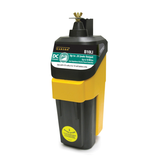
Page 11: B10Li Installation
B10LI Fence Controller Installation Overview of Installed Fence Controller Option 1: Connect to fence line via 20KV hook-up wire Fence connection 6- or 12-volt deep cycle marine battery, or four, D-Cell batteries Ground connection Option 2: Connect to fence line directly... - Page 12 STEP 1: Connect to Battery WARNING: Never connect a battery powered fence controller to an AC power supply . NOTE: Ensure switch is in the OFF position. Option 1: Connect to 6- or 12-volt battery Red (+) Black (–) 6- or 12-volt rechargeable deep cycle marine battery - 12 -...
- Page 13 Option 2: Install four, 1.5-volt/D-Cell batteries - 13 -...
- Page 14 STEP 2: Mount Fence Controller/Connect Ground NOTE: B10LI does NOT need to mount in a waterproof enclosure 1½“ Strip 20KV hook-up wire and connect as shown The B10LI can mount on a rod post or directly on a ground rod.
- Page 15 STEP 3: Connect Fence Terminal Option 1: Connect to fence line via 20KV hook-up wire 1½“ Strip 20KV hook-up wire and connect as shown Connect hook-up wire to FENCE terminal To fence line - 15 -...
- Page 16 Aluminum/Steel/Poly wire connection Part no. 07110-96 Poly tape connection Part no. PTCC1 Poly rope connection Part no. PRS2 Check fence system reliability • IMPROPER CONNECTION POINTS WILL AFFECT THE PERFORMANCE OF YOUR FENCE CONTROLLER! • Make sure splices and insulators are sound and secure. - 16 -...
- Page 17 Option 2: Connect directly to fence line Ensure metal bar makes solid contact with fence line Fence line Check fence system reliability • IMPROPER CONNECTION POINTS WILL AFFECT THE PERFORMANCE OF YOUR FENCE CONTROLLER! • Make sure splices and insulators are sound and secure. - 17 -...
-
Page 18: B10Li Operation
B10LI Fence Controller Operation Fence terminal • connect to fence line Fence OK • light flashes when voltage is on fence line Ground terminal • connect to additional ground rods ON1 Setting (high power) ON2 Setting (low power) • for longer fences or •... -
Page 19: Electric Fencing Basics
At that point the circuit is complete and the animal instantly receives an electrical shock. Tip: For permanent, high tensile fence installation instructions, refer to Zareba’s High Tensile Electric Fence Guide available at zarebasystems .com . - 19 -... -
Page 20: Electric Fence Components
Electric Fence Components Fence controller (page 4) Ground system (pages 7, 14, and 22) Gate openings (page 29) Fence posts (page 24) Lightning/ surge protection (page 30) - 20 -... - Page 21 Fence wire (page 27) Insulators (page 26) - 21 -...
-
Page 22: Grounding System
Grounding System Overview of Grounding System An effective ground system consists of: • (3) 6’ to 8’ ground rods (part no. 07104-96 or GR8) • (3) ground rod clamps (part no. 07105-96 or CGR1) • 20 KV insulated hook-up wire (part no. UGC50, UGC250, 1404-92 or 7090-92) Fence Controller... - Page 23 Grounding in Dry or Frozen Ground Animal makes contact with BOTH hot and ground wire to recieve shock Fence controller Hot fence wire Ground return wire Hot fence wire Standard ground system Additional ground rod every 1,300’ In dry, sandy or frozen soil a typical grounding system is insufficient because electricity can not flow back to the fence controller.
-
Page 24: Fence Posts
Fence Posts Fence posts fall into two categories: corner/gate posts, which must withstand tension; and line posts, which simply support the fence line between corner/gate posts. Post material varies and should be selected by fence type. Electric fencing will usually use fewer posts than conventional barbed or woven-wire fencing, making it less expensive and easier to install. - Page 25 Post Selection Guide Post Type: Wood Plastic Steel Fiber- Metal Post Step-in T-post, glass Rod Post Post U-post, T-post/ Y-post Rod Post Used for: Corner Posts (limited) Line Posts Use With Fence Type: Portable Semi- Permanent Equine Permanent High Tensile - 25 -...
-
Page 26: Insulators
Insulators Insulators isolate the electric fence wire(s) to prevent shorting and electric current leakage, while also keeping the wires properly spaced. Select your insulators to fit the type of post and fence wire you are using. We recommend Red Snap’r plastic insulators designed for ®... -
Page 27: Fence Wire
Fence Wire Electric fence wire carries the electrical current from the fence control- ler around the perimeter of the fence. Galvanized steel and aluminum wire carry electricity best. Poly wire, tape and rope have strands of conductive wire twisted or woven into the fabric and are ideal for electric fencing because of its ease-of-use, light weight and visibility. - Page 28 To maximize power on the fence, good electrical connections and splices are critical. Splicing Techniques Metal Wire Step 1 Never use loose or single-wrap splices Step 2 Poly Wire Tie any simple knot such as a square knot. Strip back and cut poly strands leaving two inches of conductive wires exposed.
-
Page 29: Gate Openings
Gate Openings Gate openings can be installed a variety of ways. Typically the same fence wire is used across the opening. If a metal gate or spring gate is used, 20 KV insulated hook-up wire should be used to carry the elec- trical current under the gate opening. -
Page 30: Lightning/Surge Protection
Lightning is one of the main causes of fence controller failure. If a storm is forecast, disconnect your fence controller from the fence in advance, and unplug if it is an AC-powered unit. Using a Zareba Cut-Off Switch (part no. COS1) is a simple way to quickly disconnect your fence controller. - Page 31 Storm Guard (part no. 01667-92) – Helps protect fence controllers rated at 1 joule of energy output or greater from lightning strikes. Spring Gate Kit (part no. SG1) – Spring coil helps to dissipate lightning surges. AC Surge Suppressor (part no. 1549-96) – Protects AC-powered fence controllers from power surges up to 6,000 volts.
-
Page 32: Electric Fence Design
Electric Fence Design Design Your Fence Now that you understand how each component works in your fence, sketch your fence layout to get a count of materials you’ll need, including number of posts, wires, insulators, gate openings, etc. Tip: An electric fence line does not have to be constructed in a ... - Page 33 Estimate Your Electric Fence Supplies Use the chart below to get a rough idea of what you’ll need for different size enclosures. Tip: Visit zarebasystems .com to use our online Fence Builder . It will recommend the correct products in the correct amounts for your electric fence .
- Page 34 Fence Configurations By Species Tip: Electric fence systems can be built in any configuration as needed by the end user . The following pages show recommended voltage levels and wire spacings to safely contain different species . Voltage for Cows: 2,000–3,000 v Voltage for Bulls: 3,000–4,000 v •...
- Page 35 Voltage: 4,000–5,000 v • thick coats/determined animals require more voltage; 4-wire may need to deter predators 7-wire 6-wire 1-wire 70" 42" total total 10" 10 " 10" 18"– 8" 10" 24” total 6" 10" 6" 10" 10" 6" 10" 6" Less space Taller fence to Portable/...
- Page 36 Voltage: 1,000–2,000 v Voltage: 700–1,000 v • smaller animals require • use to contain/deter or closer wire spacing and prevent jumping or 4-wire 4-wire wire close to ground digging 5-wire 24" total 16" total 6" 4" 6" 3" 3" 6" 3"...
-
Page 37: Testing/Troubleshooting
Metal object Bad or Fence line Faulty vegetation touching incorrect touching a connections against the fence line insulator fence post at gate fence line openings If you cannot resolve the problem please call Zareba Systems at 800-800-1819. - 37 -... - Page 38 Regular testing and maintenance of your electric fence system is important to assure performance. We recommend Zareba voltage testers DEFT-1 or RSVT8 for this purpose. Tip: Testing voltage by touching the fence line with your hand or a weed is not recommended . In addition, if you do this wearing rubber-soled shoes you will NOT feel a shock .
- Page 39 Verify weeds, branches or other debris are not touching the fence line. STEP 6: If you are still getting inadequate voltage readings visit ZarebaSystems.com for further tips or call Zareba Systems customer service at 800-800-1819. - 39 -...
-
Page 40: Fence Controller Warranty
If any covered defect occurs during the warranty, return the product for replacement or repair, with freight prepaid, to any Authorized Repair Center or directly to Zareba Systems ®... - Page 41 LIMITATION OF DAMAGES The directions for use of this product should be followed carefully. It is impossible to eliminate all risk inherently associated with use of the product. The effectiveness of Zareba Systems ® brands of fence controllers may depend on the effectiveness of connections, interruption of...
- Page 42 Notes - 42 -...
- Page 43 Notes - 43 -...
- Page 44 Woodstream Corp. 69 N. Locust Street Lititz, PA 17543 Contact us: ZarebaSystems.com info@zarebasystems.com 800-800-1819 Part # 0077368-002 Rev1...
Need help?
Do you have a question about the B10LI and is the answer not in the manual?
Questions and answers
How do you set it up?