
Related Manuals for Amazone Centaya 3000 Special

Summary of Contents for Amazone Centaya 3000 Special
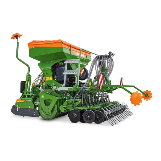
- Page 1 Original operating manual Pneumatic pack top seed drill Centaya 3000 Special SmartLearning www.amazone.de...
- Page 2 Please enter the identification data of the implement. The identification data can be found on the rating plate.
-
Page 3: Table Of Contents
Noise development data Warning symbols Permitted mounting categories 4.5.1 Positions of the warning symbols Drivable slope inclination 4.5.2 Layout of the warning symbols 4.5.3 Description of the warning symbols Rating plate on the implement MG7508-EN-GB | B.1 | 31.08.2022 | © AMAZONE... - Page 4 Using the loading board steps 10 Repairing the implement 6.4.17 Preparing the metering unit for operation 10.1 Cleaning the implement Preparing the machine for road 10.2 Maintaining the implement travel 10.2.1 Maintenance schedule MG7508-EN-GB | B.1 | 31.08.2022 | © AMAZONE...
- Page 5 11.1 Installing a lashing point in the hopper 11.2 Lifting the implement 11.3 Lashing the implement 12 Appendix 12.1 Bolt tightening torques 12.2 Other applicable documents 13 Directories 13.1 Glossary 13.2 Index MG7508-EN-GB | B.1 | 31.08.2022 | © AMAZONE...
-
Page 7: About This Operating Manual
CAUTION Indicates a threat with low risk for light or moderately severe physical injuries. 1.1.2 Further instructions CMS-T-00002416-A.1 IMPORTANT Indicates a risk for damage to the implement. MG7508-EN-GB | B.1 | 31.08.2022 | © AMAZONE... -
Page 8: Instructions
CMS-T-005678-B.1 Reactions to instructions are marked with an arrow. Example: 1. Instruction 1 Reaction to instruction 1 2. Instruction 2 1.1.3.2 Alternative instructions CMS-T-00000110-B.1 Alternative instructions are introduced with the word "or". MG7508-EN-GB | B.1 | 31.08.2022 | © AMAZONE... -
Page 9: Lists
Lists without an essential order are shown as a list with bullets. Example: Point 1 Point 2 1.1.5 Item numbers in figures CMS-T-000023-B.1 A framed number in the text, e.g. a 1 , indicates an item number in an adjacent figure. MG7508-EN-GB | B.1 | 31.08.2022 | © AMAZONE... -
Page 10: Other Applicable Documents
Your suggestions for improvement help us Technische Redaktion to create ever more user-friendly operating manuals. Postfach 51 Please send us your suggestions by post, fax or D-49202 Hasbergen email. Fax: +49 (0) 5405 501-234 E-Mail: td@amazone.de MG7508-EN-GB | B.1 | 31.08.2022 | © AMAZONE... -
Page 11: Safety And Responsibility
2.1.2.1.1 Requirements for all persons working with the machine CMS-T-00002310-A.1 If the machine is used improperly, people can be injured or killed. To prevent accidents due to improper use, every person who works with MG7508-EN-GB | B.1 | 31.08.2022 | © AMAZONE... - Page 12 Farmers are basically familiar with working with agricultural implements and can instruct agricultural helpers in how to use the implements if necessary. They can perform odd tasks and simple maintenance and repair work on agricultural implements themselves. MG7508-EN-GB | B.1 | 31.08.2022 | © AMAZONE...
- Page 13 Passengers can fall, be run over and severely injured or killed due to machine movements. Ejected objects can hit and injure passengers. Do not let anybody ride on the machine. Do not let anybody climb onto the driving machine. MG7508-EN-GB | B.1 | 31.08.2022 | © AMAZONE...
- Page 14 Non-observance of the technical limits values of the machine can result in accidents and serious personal injury or even death. Moreover, the machine can be damaged. The technical limit values can be found in the Technical Data. Comply with the technical limit values. MG7508-EN-GB | B.1 | 31.08.2022 | © AMAZONE...
- Page 15 Missing warning symbols increase the risk of serious and lethal personal injury. Clean dirty warning symbols. Immediately replace any damaged and illegible warning symbols. Put the intended warning symbols on spare parts. MG7508-EN-GB | B.1 | 31.08.2022 | © AMAZONE...
-
Page 16: Knowing And Preventing Dangers
Never look for leaks with your bare hands. Keep your body and face away from leaks. If liquids penetrate the body, consult a doctor immediately. MG7508-EN-GB | B.1 | 31.08.2022 | © AMAZONE... -
Page 17: Safe Operation And Handling Of The Machine
Use only suitable tractors for coupling and transporting the implement. When the implement is coupled onto the tractor, make sure that the tractor's connecting device meets the implement requirements. Couple the implement properly to the tractor. MG7508-EN-GB | B.1 | 31.08.2022 | © AMAZONE... - Page 18 If the machine is not properly prepared for road travel, it can result in serious traffic accidents. Check the lighting and identification for road travel for proper function. Remove coarse dirt from the implement. Follow the instructions in the section "Preparing the implement for road travel". MG7508-EN-GB | B.1 | 31.08.2022 | © AMAZONE...
-
Page 19: Safe Maintenance And Modification
To ensure that the operating permit remains valid in accordance with national and international regulations, ensure that the specialist workshop only uses conversion parts, spare parts and special equipment approved by AMAZONE. MG7508-EN-GB | B.1 | 31.08.2022 | © AMAZONE... - Page 20 Remove the ignition key and carry it with you. Remove the key from the battery circuit breaker. Wait until all parts that are still running come to a stop and that hot parts cool down. MG7508-EN-GB | B.1 | 31.08.2022 | © AMAZONE...
- Page 21 Never linger under raised implement parts. If you have to work on or under raised machine parts, lower the implement parts or secure the raised implement parts with a mechanical support or hydraulic locking device. MG7508-EN-GB | B.1 | 31.08.2022 | © AMAZONE...
- Page 22 CMS-T-00002325-B.1 Special equipment, accessories, and spare parts Special equipment, accessories, and spare parts that do not meet AMAZONE requirements can impede the operational safety of the implement and cause accidents. Only use original parts or parts that meet AMAZONE requirements.
-
Page 23: Safety Routines
If you are not sure if the protective equipment is properly installed and functional, have the protective equipment checked by a qualified specialist workshop. Make sure that the protective devices are properly installed and functional before any work on the implement. Replace damaged protective equipment. MG7508-EN-GB | B.1 | 31.08.2022 | © AMAZONE... - Page 24 When climbing up and down, never hold onto the control elements. Accidental actuation of control elements can unintentionally activate potentially dangerous functions. When climbing down, never jump off of the machine. MG7508-EN-GB | B.1 | 31.08.2022 | © AMAZONE...
-
Page 25: Intended Use
AMAZONE. Uses other than those specified under the intended use are considered as improper. The manufacturer is not liable for any damage resulting from improper use, solely the operator is responsible. MG7508-EN-GB | B.1 | 31.08.2022 | © AMAZONE... -
Page 26: Product Description
4 | Product description Product description CMS-T-00009762-A.1 4.1 Implement overview CMS-T-00009764-A.1 CMS-I-00006840 Work floodlights Segment distributor head Tramline marker Exact following harrow Seeding coulter QuickLink catching sockets Metering unit MG7508-EN-GB | B.1 | 31.08.2022 | © AMAZONE... - Page 27 4 | Product description Implement overview CMS-I-00006841 Threaded cartridge Rating plate Seed line hoses CMS-I-00006842 Cabinet for hydraulic hose lines MG7508-EN-GB | B.1 | 31.08.2022 | © AMAZONE...
-
Page 28: Function Of The Implement
Shelf for sacks Mounting kit for radar sensor Suction guard screen Hopper extension 500 l Tramline segments Low level sensor MG7508-EN-GB | B.1 | 31.08.2022 | © AMAZONE... -
Page 29: Protective Equipment
CMS-I-00005315 4.4.2 Fan guard screen CMS-T-00007659-A.1 The fan guard screen 1 protects against injuries caused by rotating parts and damage due to foreign objects. CMS-I-00005368 MG7508-EN-GB | B.1 | 31.08.2022 | © AMAZONE... -
Page 30: Road Safety Bars
The road safety bars 1 cover the tines of the exact following harrow to protect against injury and damage. CMS-I-00005527 4.5 Warning symbols CMS-T-00009770-A.1 4.5.1 Positions of the warning symbols CMS-T-00009857-A.1 CMS-I-00006972 MG7508-EN-GB | B.1 | 31.08.2022 | © AMAZONE... - Page 31 4 | Product description Warning symbols CMS-I-00006976 CMS-I-00006977 MG7508-EN-GB | B.1 | 31.08.2022 | © AMAZONE...
- Page 32 4 | Product description Warning symbols CMS-I-00006978 CMS-I-00006984 MG7508-EN-GB | B.1 | 31.08.2022 | © AMAZONE...
-
Page 33: Layout Of The Warning Symbols
Make sure that there is nobody standing in the danger area. MD 274 Risk of crushing due to the implement falling over Empty the seed hopper. Before you park the empty pack top implement, install the parking supports. MD274 CMS-I-00004664 MG7508-EN-GB | B.1 | 31.08.2022 | © AMAZONE... - Page 34 Do not let anybody ride on the implement. Do not let anybody climb onto the driving implement. CMS-I-000081 MD 242 Risk of injury due to breaking charging sieve Never climb onto the charging sieve MD242 CMS-I-00005074 MG7508-EN-GB | B.1 | 31.08.2022 | © AMAZONE...
- Page 35 Never look for leaks in hydraulic hose lines using your hand or fingers. Never attempt to plug leaks in hydraulic hose lines using your hand or fingers. If you are injured by hydraulic oil, consult a doctor immediately. CMS-I-000216 MG7508-EN-GB | B.1 | 31.08.2022 | © AMAZONE...
- Page 36 Only couple the implement to tractors with a maximum tractor hydraulic pressure of 210 bar. CMS-I-00000486 MD 100 Risk of accidents due to improperly attached lifting gear Only attach the lifting gear at the marked positions. CMS-I-000089 MG7508-EN-GB | B.1 | 31.08.2022 | © AMAZONE...
-
Page 37: Rating Plate On The Implement
4.6 Rating plate on the implement CMS-T-00004505-F.1 Implement number Vehicle ID number Product Permissible technical implement weight Model year Year of manufacture CMS-I-00004294 4.7 Threaded cartridge CMS-T-00001776-D.1 The threaded cartridge contains the following items: Documents Aids CMS-I-00002306 MG7508-EN-GB | B.1 | 31.08.2022 | © AMAZONE... -
Page 38: Universal Operating Tool
CMS-I-00004418 The mySeeder app can be obtained from the Apple App Store or the Google Play Store. To do so, use the QR code or the link www.amazone.de/ qrcode_mySeeder. CMS-I-00004417 MG7508-EN-GB | B.1 | 31.08.2022 | © AMAZONE... -
Page 39: Hopper
The conveyor fan is driven by a hydraulic motor. The fan guard screen protects the operator against injuries caused by rotating parts and the fan against foreign objects. CMS-I-00002467 MG7508-EN-GB | B.1 | 31.08.2022 | © AMAZONE... -
Page 40: Cyclone Separator
As soon as the implement is raised when turning at the end of a field, the electric motor switches off and the metering roller comes to a halt. MG7508-EN-GB | B.1 | 31.08.2022 | © AMAZONE... -
Page 41: Metering Roller
Single shoot, 1-chamber hopper Metering unit Calibration flap Conveyor section CMS-I-00006472 4.14 Mounting frame CMS-T-00004881-B.1 The pack top seed drill is fastened on the soil tillage implement 2 with two mounts 1 . CMS-I-00003592 MG7508-EN-GB | B.1 | 31.08.2022 | © AMAZONE... -
Page 42: Lighting
4.15.1.1 Rear lighting and identification for road travel CMS-T-00001498-E.1 Warning signs Reflector, red Rear lights, brake lights, and turn indicators Reflector, yellow CMS-I-00004545 NOTE The lighting and identification for road travel can vary depending on the national regulations. MG7508-EN-GB | B.1 | 31.08.2022 | © AMAZONE... -
Page 43: Work Lights
The coulter array lighting 1 enables better visibility of the seeding coulters in the dark. The coulter array lighting is switched on and off together with the work floodlights via the control terminal or control computer. CMS-I-00006848 MG7508-EN-GB | B.1 | 31.08.2022 | © AMAZONE... -
Page 44: Radar Sensor
A maximum of twelve tramline segments can be controlled per distributor head. The tramline segments in the segment distributor CMS-I-00003165 head can be expanded, repositioned or replaced with segments without flaps. MG7508-EN-GB | B.1 | 31.08.2022 | © AMAZONE... -
Page 45: One-Sided Switching
The coulter pressure and the placement depth can be adjusted. CMS-I-00005976 For soil tillage without seeding, the coulters can be lifted. MG7508-EN-GB | B.1 | 31.08.2022 | © AMAZONE... -
Page 46: Rotec Coulter
CMS-I-00005193 The Control 10 depth control disc 1 has a 10 mm- wide contact area and is used on heavy soils. CMS-I-00005195 MG7508-EN-GB | B.1 | 31.08.2022 | © AMAZONE... -
Page 47: Exact Following Harrow
4.22 Coulter harrow CMS-T-00006648-A.1 The harrow tines 1 of the coulter harrow cover the deposited metered material evenly with loose soil. The pitch and the height of the harrow tines can be adjusted. CMS-I-00004734 MG7508-EN-GB | B.1 | 31.08.2022 | © AMAZONE... -
Page 48: Tramline Marker
The length and scope of action of the track marker can be adjusted. The track markers must be lifted before the track markers pass an obstacle or the tractor turns around. CMS-I-00005114 MG7508-EN-GB | B.1 | 31.08.2022 | © AMAZONE... -
Page 49: Technical Data
2,029 mm ± 3 mm 5.4 Optimal working speed CMS-T-00009799-A.1 Working speed, depending on the soil tillage Seeding coulter implement TwinTeC Special coulter 8 km/h to 12 km/h RoTeC coulter 6 km/h to 12 km/h MG7508-EN-GB | B.1 | 31.08.2022 | © AMAZONE... -
Page 50: Soil Tillage Tools
Up the slope and down the slope Up the slope 10 % Down the slope 10 % 5.9 Performance characteristics of the tractor CMS-T-00009803-A.1 Type Engine rating Centaya 3000 Special Starting at 81 kW / 110 PS MG7508-EN-GB | B.1 | 31.08.2022 | © AMAZONE... - Page 51 At least 10 l/min at 150 bar HLP68 DIN51524 Implement hydraulic oil The hydraulic oil is suitable for the combined hydraulic oil circuits of all standard tractor manufacturers. Control units Depending on the implement equipment MG7508-EN-GB | B.1 | 31.08.2022 | © AMAZONE...
-
Page 52: Preparing The Implement
Total weight of front-mounted implement or front ballast Permissible total weight of rear-mounted implement or rear ballast Distance between the centre of gravity of the front-mounted implement or the front ballast and the centre of the front axle MG7508-EN-GB | B.1 | 31.08.2022 | © AMAZONE... - Page 53 T b 0,2 T b Vmin Vmin Vmin CMS-I-00000513 2. Calculate the actual front axle load. × × - × G a b T b G c + d Vtat Vtat Vtat CMS-I-00000516 MG7508-EN-GB | B.1 | 31.08.2022 | © AMAZONE...
- Page 54 Tyre load according to according to capacity for two tractor operating calculation tractor tyres manual ≤ Minimum front ballasting ≤ Total weight ≤ ≤ Front axle load ≤ ≤ Rear axle load MG7508-EN-GB | B.1 | 31.08.2022 | © AMAZONE...
-
Page 55: Calculating The Permissible Payload
1. Plug in the connector of the ISOBUS line 1 or the control computer line 2 . 2. Route the ISOBUS line with sufficient freedom of movement and without chafing or pinching points. CMS-I-00006891 MG7508-EN-GB | B.1 | 31.08.2022 | © AMAZONE... -
Page 56: Coupling The Power Supply
CMS-I-00000121 Type of actuation Function Symbol Latching Permanent oil circulation Oil circulation until action is Momentary executed Free oil flow in the tractor control Floating unit MG7508-EN-GB | B.1 | 31.08.2022 | © AMAZONE... - Page 57 Install the supplied coupling sleeve on the pressureless hydraulic oil return. 1. Depressurise the hydraulic system between the tractor and the implement using the tractor control unit. 2. Clean the hydraulic plugs. MG7508-EN-GB | B.1 | 31.08.2022 | © AMAZONE...
-
Page 58: Coupling The 3-Point Mounting Frame
1 under the pack top seed drill. The QuickLink pins for the pack top seed drill are lined up with the QuickLink catching sockets of the soil tillage implement. CMS-I-00006856 MG7508-EN-GB | B.1 | 31.08.2022 | © AMAZONE... - Page 59 To prevent the parking supports from falling out of the mount while driving, remove the parking supports. CMS-I-00007204 11. Remove the parking supports 1 from the implement 2 on both sides. MG7508-EN-GB | B.1 | 31.08.2022 | © AMAZONE...
- Page 60 1 . CMS-I-00003485 14. Connect the supply line 2 for the rear lighting and identification for road travel to the soil tillage implement 1 . CMS-I-00004527 MG7508-EN-GB | B.1 | 31.08.2022 | © AMAZONE...
-
Page 61: Preparing The Implement For Operation
2. Place the lever 2 on an level contact surface on the top link 3 . 3. Tighten the nut. To ensure that the working position sensor is resting on a level surface, CMS-I-00002608 completely lift and lower the implement. MG7508-EN-GB | B.1 | 31.08.2022 | © AMAZONE... -
Page 62: Setting The Fill Level Sensor
At higher spread rates, the fill level sensor must be attached in the upper area of the hopper. 1. Open the roller tarpaulin. 2. Remove the linch pin 1 . CMS-I-00005314 3. Take out the charging sieve 1 . CMS-I-00006778 MG7508-EN-GB | B.1 | 31.08.2022 | © AMAZONE... -
Page 63: Filling The Hopper
6.4.4 Filling the hopper CMS-T-00009947-A.1 1. lower the implement. 2. Unlock the loading board 1 with the locking mechanism 2 . 3. Swivel the loading board down. 4. Open the roller tarpaulin. CMS-I-00005277 MG7508-EN-GB | B.1 | 31.08.2022 | © AMAZONE... -
Page 64: Adjusting The Coulter Pressure On The Twintec Special Coulter
The coulter pressure is adjusted with two adjustment spindles. The adjustment spindles are located on the right and left side of the implement respectively. 2. Put the universal operating tool on the adjustment spindle 1 . CMS-I-00007037 MG7508-EN-GB | B.1 | 31.08.2022 | © AMAZONE... - Page 65 Comfort hydraulic system, see ISOBUS software operating manual "Pre- selection for hydraulic functions". Adjust the values for the coulter pressure on implements without Comfort hydraulic system, see ISOBUS software operating manual "Coulter pressure settings". MG7508-EN-GB | B.1 | 31.08.2022 | © AMAZONE...
-
Page 66: Adjusting The Coulter Pressure On The Rotec Coulter
Two pins in an adjuster segment act as the stop for the hydraulic cylinder. The scale 1 serves as orientation for adjusting the pins. CMS-I-00006171 MG7508-EN-GB | B.1 | 31.08.2022 | © AMAZONE... -
Page 67: Adjusting The Seed Rate Increase
30 m at working speed and then check the work pattern. 6.4.7 Adjusting the seed rate increase CMS-T-00010570-A.1 The seed rate can be increased if necessary. This can be the case e.g. when changing to heavy soils. MG7508-EN-GB | B.1 | 31.08.2022 | © AMAZONE... -
Page 68: Adjusting The Placement Depth On The Twintec Special Coulter
6.4.8 Adjusting the placement depth on the TwinTeC Special coulter CMS-T-00010104-A.1 NOTE The adjustment of the seed placement depth must be adapted to the respective operating conditions. The optimum adjustment can only be determined during field operation. MG7508-EN-GB | B.1 | 31.08.2022 | © AMAZONE... - Page 69 The scale 1 serves as orientation. CMS-I-00006884 To reduce the coulter pressure, turn the universal operating tool counter- clockwise - To increase the coulter pressure, turn the universal operating tool clockwise + . MG7508-EN-GB | B.1 | 31.08.2022 | © AMAZONE...
- Page 70 CMS-I-00006162 To spread legumes, install the press rollers in the upper position. 10. Install the bolt 5 . 11. Install the washer 2 . 12. Install the nut 1 and tighten it. MG7508-EN-GB | B.1 | 31.08.2022 | © AMAZONE...
-
Page 71: Adjusting The Placement Depth On The Rotec Coulter
"Checking the placement depth". 4. If the required placement depth has not yet been reached, the coulter pressure must also be adjusted, see "Adjusting the coulter pressure on the RoTeC coulter". MG7508-EN-GB | B.1 | 31.08.2022 | © AMAZONE... -
Page 72: Adjusting The Coulter Harrow
Install the pin 2 in the hole shown. The harrow tine is resting on the plate 3 . To check the setting, seed for approx. 30 m at working speed and then check the work pattern. CMS-I-00003187 MG7508-EN-GB | B.1 | 31.08.2022 | © AMAZONE... - Page 73 2 . As a result, the harrow tine does not protrude into the neighbouring coulters. IMPORTANT Damage to the coulters due to folded harrow tines Do not remove the locking pin. CMS-I-00003184 MG7508-EN-GB | B.1 | 31.08.2022 | © AMAZONE...
- Page 74 1. Lift the implement. 2. Remove the pins 1 and 2 . CMS-I-00003188 3. fold up the harrow 1 . 4. Install the pins 2 and 3 in the indicated hole. CMS-I-00003183 MG7508-EN-GB | B.1 | 31.08.2022 | © AMAZONE...
-
Page 75: Adjusting The Exact Following Harrow
The distance must be 230-280 mm. Depending on the equipment, the exact following harrows can be adjusted with removable bolts or using the universal operating tool. Both versions are CMS-I-00004668 listed here. MG7508-EN-GB | B.1 | 31.08.2022 | © AMAZONE... - Page 76 6. Install the washers 2 . 7. Install the bolts 1 . 8. Tighten the bolts. To check the setting, seed for approx. 30 m at working speed and then check the work pattern. CMS-I-00006021 MG7508-EN-GB | B.1 | 31.08.2022 | © AMAZONE...
- Page 77 CMS-I-00006062 To lock the holding arm fold the handle 2 down. To check the setting, seed for approx. 30 m at working speed and then check the work pattern. CMS-I-00006063 MG7508-EN-GB | B.1 | 31.08.2022 | © AMAZONE...
- Page 78 The optimum adjustment can only be determined during field operation. 1. Take the lever 1 out of the transport lock 2 and pull it up. CMS-I-00004673 MG7508-EN-GB | B.1 | 31.08.2022 | © AMAZONE...
- Page 79 To adjust the pressure, a stop is pegged onto the tube. The higher the position of the stop, the greater the exact following harrow pressure. MG7508-EN-GB | B.1 | 31.08.2022 | © AMAZONE...
- Page 80 1 . 3. Relieve the lever and fasten it in the transport lock. To check the setting, seed for approx. 30 m at working speed and then check the work pattern. CMS-I-00004671 MG7508-EN-GB | B.1 | 31.08.2022 | © AMAZONE...
-
Page 81: Adjusting The Tramline Marker
To increase the effect of the track disc increase the pitch To reduce the effect of the track disc, reduce the pitch. 3. Move the clamping part 3 in the grid 2 to the desired position. CMS-I-00003171 MG7508-EN-GB | B.1 | 31.08.2022 | © AMAZONE... -
Page 82: Adjusting The Row Spacing
2 to install the sealing plugs 1 in the seed outlets To reduce the row spacing, CMS-I-00003247 use the tool 2 to remove the sealing plugs 1 from the seed outlets. MG7508-EN-GB | B.1 | 31.08.2022 | © AMAZONE... -
Page 83: Setting Up The Speed Sensor
The speed sensor on the implement can be used for this. To set up the speed sensor on the implement, see ISOBUS software operating manual, "Setting up the speed sensor on the implement" see "control computer operating manual." MG7508-EN-GB | B.1 | 31.08.2022 | © AMAZONE... -
Page 84: Operating The One-Sided Switching
"ISOBUS software" operating manual see "control computer" operating manual. To halve the seed rate when using half the working width, see "ISOBUS software" operating manual see "control computer" operating manual. MG7508-EN-GB | B.1 | 31.08.2022 | © AMAZONE... -
Page 85: Using The Loading Board Steps
6. Check whether the transport lock is properly locked. 6.4.17 Preparing the metering unit for operation CMS-T-00009826-A.1 6.4.17.1 Putting the metering unit into operation CMS-T-00010369-A.1 If work is started without calibration, Close the calibration flap 1 . CMS-I-00006791 MG7508-EN-GB | B.1 | 31.08.2022 | © AMAZONE... - Page 86 Metering volume in cm materia 3.75 Beans Buckwh Spelt Peas Flax (dresse Barley Grass seeds Oats Millet Carawa Lupines Lucerne Maize Poppy Oilseed (moist dressed Fodder radish Phaceli Rapese clover Mustard Soya Sunflow Turnips MG7508-EN-GB | B.1 | 31.08.2022 | © AMAZONE...
- Page 87 1. Remove the locking ring 4 . 2. Remove the end plate 3 . 3. Remove the metering wheels 2 and intermediate plates 1 . CMS-I-00002550 MG7508-EN-GB | B.1 | 31.08.2022 | © AMAZONE...
- Page 88 1 symmetrically at the centre 2 . 5. Install the metering wheels and intermediate plates. 6. Install the end plate. 7. Install the locking ring. CMS-I-00002552 MG7508-EN-GB | B.1 | 31.08.2022 | © AMAZONE...
- Page 89 3. Take the calibration bucket 1 out of the holder. CMS-I-00006874 4. Slide the calibration bucket 2 into the guide rails 1 so that the calibration bucket is positioned underneath the metering unit. CMS-I-00006785 MG7508-EN-GB | B.1 | 31.08.2022 | © AMAZONE...
- Page 90 10. Park the socket wrench in the holder 1 . To empty the metering unit and the metering roller, refer to the ISOBUS software operating manual, "Emptying". CMS-I-00005259 see "control computer" operating manual. MG7508-EN-GB | B.1 | 31.08.2022 | © AMAZONE...
- Page 91 22. park the sliding shutter 2 on the metering unit housing. 23. Swivel the bolts 3 in front of the sliding shutter. 24. Tighten the bolts with the socket wrench 1 . CMS-I-00005255 MG7508-EN-GB | B.1 | 31.08.2022 | © AMAZONE...
- Page 92 25. Close the calibration flap 1 . CMS-I-00006791 26. Take the calibration bucket 2 from the guide rails 1 . 27. Empty the calibration bucket. CMS-I-00006792 28. Put the calibration bucket 1 in the parking position. CMS-I-00006875 MG7508-EN-GB | B.1 | 31.08.2022 | © AMAZONE...
- Page 93 The hopper is at least one quarter filled with spreading material To unlock the calibration bucket, remove the linch pin 1 from the holder. CMS-I-00006873 2. Take the calibration bucket 1 out of the holder. CMS-I-00006874 MG7508-EN-GB | B.1 | 31.08.2022 | © AMAZONE...
- Page 94 ISOBUS software operating manual, "Calibration menu" see "control computer" operating manual. To start the calibration via the control terminal, refer to the ISOBUS software operating manual, "Calibration menu" CMS-I-00006860 see "control computer" operating manual. MG7508-EN-GB | B.1 | 31.08.2022 | © AMAZONE...
- Page 95 8. Fold down the bracket 1 on the ascent. CMS-I-00005700 9. Hang the scale 2 on the bracket 1 on the ascent. 10. Hang the collapsible bucket 3 on the scale. CMS-I-00005716 MG7508-EN-GB | B.1 | 31.08.2022 | © AMAZONE...
- Page 96 12. Take the calibration bucket 2 from the guide rails 1 . 13. Pour the seed from the calibration bucket into the collapsible bucket. CMS-I-00006792 14. Put the calibration bucket 1 in the parking position. CMS-I-00006875 MG7508-EN-GB | B.1 | 31.08.2022 | © AMAZONE...
-
Page 97: Preparing The Machine For Road Travel
6.5.2 Folding the tramline marker on the exact following harrow CMS-T-00007448-B.1 To be able to move the tramline marker into transport position, no tramlines may be created in the ISOBUS software or on the control computer. MG7508-EN-GB | B.1 | 31.08.2022 | © AMAZONE... -
Page 98: Putting The Road Safety Bars On The Exact Following Harrow
2. Push the road safety bars 1 over the tines. 3. Secure the road safety bars with the tensioners 4. Check for firm seating. If the tensioners do not provide enough tension, guide the tensioner through the tine coils. CMS-I-00005185 MG7508-EN-GB | B.1 | 31.08.2022 | © AMAZONE... -
Page 99: Using The Implement
The outer harrow elements must be adjusted such that the soil is guided back and a trackless seedbed is created. The greater the forward speed, the further the outer harrow elements have to be set outwards. MG7508-EN-GB | B.1 | 31.08.2022 | © AMAZONE... -
Page 100: Unfolding The Tramline Marker
7.4 Using the implement CMS-T-00004492-C.1 1. Align the implement parallel to the ground. 2. Lower the implement on the field. 3. Move the hydraulic system of the 3-point power lift into float position. MG7508-EN-GB | B.1 | 31.08.2022 | © AMAZONE... -
Page 101: Checking The Placement Depth
To prevent seed accumulations, give the tractor control unit for the fan drive priority. To prevent lateral loads when driving in curves on the headlands, Raise the implement. MG7508-EN-GB | B.1 | 31.08.2022 | © AMAZONE... -
Page 102: Performing Maintenance Work During Operation
When the direction of the implement matches that of the direction of travel, lower the implement. 7.7 Performing maintenance work during operation CMS-T-00010368-A.1 Clean the suction guard screen or cyclone separator, see page 128. MG7508-EN-GB | B.1 | 31.08.2022 | © AMAZONE... -
Page 103: Eliminating Faults
The height of the coulter harrow is See "Adjusting the TwinTeC incorrectly set. coulter" > "Adjusting the harrow height" The harrow tines of the coulter see page 101 harrow are worn. MG7508-EN-GB | B.1 | 31.08.2022 | © AMAZONE... - Page 104 "Cleaning the metering housing. unit". The lighting for road travel has a Lamp or lighting supply line is Replace the lamp. malfunction. damaged. Replace the lighting supply line. MG7508-EN-GB | B.1 | 31.08.2022 | © AMAZONE...
- Page 105 5. Replace the guide extension 3 . 6. Install the bolt. To install the TwinTeC seed outlet, place the guides 4 in the coulter bodies 5 . 8. Install the bolt. 9. Install the hose. MG7508-EN-GB | B.1 | 31.08.2022 | © AMAZONE...
- Page 106 4. Replace the inner scraper 2 . CMS-I-00003245 5. Install the bolt. To install the TwinTeC seed outlet, place the guides 3 in the coulter bodies 4 . 7. Install the bolt. 8. Install the hose. MG7508-EN-GB | B.1 | 31.08.2022 | © AMAZONE...
- Page 107 5. Move the harrow bracket to the desired position. 6. Install the bolt. CMS-I-00004632 7. Install the nut and tighten it. To check the setting, seed for approx. 30 m at working speed and then check the work pattern. MG7508-EN-GB | B.1 | 31.08.2022 | © AMAZONE...
- Page 108 The fan speed displayed on the control terminal or control computer is too high CMS-T-00007763-B.1 To adjust the fan speed, see "Setting the fan speed hydraulically" see "Setting the fan speed manually". MG7508-EN-GB | B.1 | 31.08.2022 | © AMAZONE...
-
Page 109: Parking The Implement
When the seed hopper is emptied, Close the quick emptying. CMS-I-00006781 9.1.2 Emptying the hopper via the metering unit CMS-T-00009847-A.1 To unlock the calibration bucket, remove the linch pin 1 from the holder. CMS-I-00006873 MG7508-EN-GB | B.1 | 31.08.2022 | © AMAZONE... - Page 110 CMS-I-00006874 3. Slide the calibration bucket 2 into the guide rails 1 so that the calibration bucket is positioned underneath the metering unit. CMS-I-00006785 4. Open the calibration flap 1 . CMS-I-00006787 MG7508-EN-GB | B.1 | 31.08.2022 | © AMAZONE...
- Page 111 14. Pull off the bearing cover 2 . When the hopper is closed off with the sliding shutter, pull the metering roller 1 out of the metering unit. 16. Pull the sliding shutter out of the metering housing. CMS-I-00005256 MG7508-EN-GB | B.1 | 31.08.2022 | © AMAZONE...
- Page 112 23. Park the sliding shutter 2 on the metering housing. 24. Swivel the bolts 3 in front of the sliding shutter. 25. Tighten the bolts with the socket wrench 1 . CMS-I-00005255 26. Close the calibration flap 1 . CMS-I-00006791 MG7508-EN-GB | B.1 | 31.08.2022 | © AMAZONE...
- Page 113 1 . 28. Empty the calibration bucket. CMS-I-00006792 29. Put the calibration bucket 1 in the parking position. CMS-I-00006875 To lock the calibration bucket, attach the linch pin 1 onto the holder. CMS-I-00006873 MG7508-EN-GB | B.1 | 31.08.2022 | © AMAZONE...
-
Page 114: Emptying The Metering Unit
Clean the metering unit after operation. 1. Switch off the fan. To unlock the calibration bucket, remove the linch pin 1 from the holder. CMS-I-00006873 3. Take the calibration bucket 1 out of the holder. CMS-I-00006874 MG7508-EN-GB | B.1 | 31.08.2022 | © AMAZONE... - Page 115 5. Open the calibration flap 1 . CMS-I-00006787 6. Loosen the bolts 3 with the socket wrench 1 . 7. Swivel the bolts to the side. 8. Take the sliding shutter 2 from its parking position. CMS-I-00005255 MG7508-EN-GB | B.1 | 31.08.2022 | © AMAZONE...
- Page 116 2 on the metering unit housing. 13. Swivel the bolts 3 in front of the sliding shutter. 14. Tighten the bolts with the socket wrench 1 . CMS-I-00005255 15. Close the calibration flap 1 . CMS-I-00006791 MG7508-EN-GB | B.1 | 31.08.2022 | © AMAZONE...
- Page 117 1 . 17. Empty the calibration bucket. CMS-I-00006792 18. Put the calibration bucket 1 in the parking position. CMS-I-00006875 To lock the calibration bucket, attach the linch pin 1 onto the holder. CMS-I-00006873 MG7508-EN-GB | B.1 | 31.08.2022 | © AMAZONE...
-
Page 118: Uncoupling The Isobus Or Control Computer
3. Hang the plug in the hose cabinet. CMS-I-00006891 9.4 Uncoupling the power supply CMS-T-00001402-G.1 1. Pull out the plug 1 for the power supply. CMS-I-00001048 2. Hang the plugs 1 in the hose cabinet. CMS-I-00001248 MG7508-EN-GB | B.1 | 31.08.2022 | © AMAZONE... -
Page 119: Uncoupling The Seeding Combination
80 mm x 80 mm in front of and behind the roller of the soil tillage implement. 5. Uncouple the lower link 2 from the implement from the tractor seat. 6. Drive the tractor forward. MG7508-EN-GB | B.1 | 31.08.2022 | © AMAZONE... -
Page 120: Disconnecting The Hydraulic Hose Lines
To set the coulter pressure to 0, see section "Adjusting the coulter pressure on the TwinTeC Special coulter" To set the placement depth to 0, see section "Adjusting the placement depth on the TwinTeC Special coulter". MG7508-EN-GB | B.1 | 31.08.2022 | © AMAZONE... - Page 121 CMS-I-00004527 If the pack top seed drill has a tramline marker, disconnect the supply line of the pack top seed drill from the soil tillage implement 1 . CMS-I-00003485 MG7508-EN-GB | B.1 | 31.08.2022 | © AMAZONE...
- Page 122 14. Disconnect the supply line for the job computer from the hose package and place it in the hose cabinet 15. Disconnect the supply line for the job computer from the tractor and place it in the hose cabinet MG7508-EN-GB | B.1 | 31.08.2022 | © AMAZONE...
- Page 123 The pack top seed drill 1 is standing on the parking supports. 17. Install the safety clips 3 on the soil tillage implement. CMS-I-00003590 18. Slowly drive the tractor with the coupled soil tillage implement 1 forward. CMS-I-00006856 MG7508-EN-GB | B.1 | 31.08.2022 | © AMAZONE...
-
Page 124: Repairing The Implement
Always maintain a minimum distance of 30 cm between the high-pressure nozzle and the implement. Do not exceed a water pressure of 120 bar. Clean the machine with a high-pressure cleaner or a hot water high-pressure cleaner. MG7508-EN-GB | B.1 | 31.08.2022 | © AMAZONE... -
Page 125: Maintaining The Implement
Checking the TwinTeC depth control wheel scraper see page 122 Checking the RoTeC furrow former see page 125 Checking the RoTeC cutting discs see page 125 Checking the hydraulic hose lines see page 138 MG7508-EN-GB | B.1 | 31.08.2022 | © AMAZONE... - Page 126 8. Install spacer discs that are not required on the opposite side of the cutting disc bearing 3 with the central bolt. 9. Install the cutting disc bearing on the coulter 1 . 10. Install the central bolt. MG7508-EN-GB | B.1 | 31.08.2022 | © AMAZONE...
-
Page 127: Checking The Twintec Depth Control Wheel
4. Replace the damaged TwinTeC depth control wheel. 5. Install the nut and washer. CMS-I-00003243 10.2.4 Checking the TwinTeC cutting discs CMS-T-00004452-D.1 INTERVAL Every 50 operating hours weekly Original disc diameter Wear limit 340 mm 300 mm MG7508-EN-GB | B.1 | 31.08.2022 | © AMAZONE... -
Page 128: Checking The Twintec Depth Control Wheel Scraper
To ensure that the TwinTeC cutting discs touch slightly, see section "Checking the TwinTeC cutting disc distance". 10.2.5 Checking the TwinTeC depth control wheel scraper CMS-T-00008936-A.1 INTERVAL Every 50 operating hours weekly 1. Lift the implement. CMS-I-00006164 MG7508-EN-GB | B.1 | 31.08.2022 | © AMAZONE... -
Page 129: Checking The Rotec Depth Control Discs And Rotec Depth Control Wheels
If a RoTeC depth control disc or RoTeC depth control wheel is damaged, replace the RoTeC depth control disc or RoTeC depth control wheel. MG7508-EN-GB | B.1 | 31.08.2022 | © AMAZONE... - Page 130 To adjust the placement depth, pull on the lever for the RoTeC depth control disc or RoTeC depth control wheel, move it up and CMS-I-00004836 engage it in the desired hole 2 . MG7508-EN-GB | B.1 | 31.08.2022 | © AMAZONE...
-
Page 131: Checking The Rotec Furrow Former
10.2.8 Checking the RoTeC cutting discs CMS-T-00010382-A.1 INTERVAL Every 50 operating hours weekly Version Original disc diameter Wear limit RoTeC coulter 317 mm 289 mm RoTeC pro coulter 402 mm 365 mm MG7508-EN-GB | B.1 | 31.08.2022 | © AMAZONE... -
Page 132: Checking The Tightening Torque For The Radar Sensor Bolts
NOTE When the tightening torque is too high, the spring- suspended sensor mount is warped and the radar sensor does not work properly. Check the tightening torque on the radar sensor. CMS-I-00002600 MG7508-EN-GB | B.1 | 31.08.2022 | © AMAZONE... -
Page 133: Cleaning The Hopper
2. Clean the charging sieve 1 . CMS-I-00006777 3. Remove the linch pin 1 . CMS-I-00005314 4. Take out the charging sieve 1 . 5. Clean the hopper with a high-pressure cleaner. CMS-I-00006778 MG7508-EN-GB | B.1 | 31.08.2022 | © AMAZONE... -
Page 134: Cleaning The Cyclone Separator
2 . 3. Loosen the wing nut 1 . 4. Remove the cover and clean it. 5. Install the cover with the wing nut. CMS-I-00002765 6. Fasten the suction cage with the clips. MG7508-EN-GB | B.1 | 31.08.2022 | © AMAZONE... -
Page 135: Cleaning The Segment Distributor Head
6. Tighten the four knurled screws by hand. 10.2.13 Cleaning the conveyor section CMS-T-00009834-A.1 INTERVAL Every 10 operating hours daily The air drawn by the fan can contain fertiliser dust or sand. These impurities can accumulate on the MG7508-EN-GB | B.1 | 31.08.2022 | © AMAZONE... - Page 136 2. Take the calibration bucket 1 out of the holder. CMS-I-00006874 3. Slide the calibration bucket 2 into the guide rails 1 so that the calibration bucket is positioned underneath the metering unit. CMS-I-00006785 MG7508-EN-GB | B.1 | 31.08.2022 | © AMAZONE...
- Page 137 To remove the deposits, aim a water jet into the seed outlets 3 and into the corrugated tube 2 . 10. Install the cover. 11. Tighten the four knurled screws by hand. CMS-I-00004702 MG7508-EN-GB | B.1 | 31.08.2022 | © AMAZONE...
- Page 138 14. Switch off the fan. CMS-I-00006791 15. Take the calibration bucket 2 from the guide rails 1 . 16. Empty the calibration bucket. CMS-I-00006792 17. Put the calibration bucket 1 in the parking position. CMS-I-00006875 MG7508-EN-GB | B.1 | 31.08.2022 | © AMAZONE...
-
Page 139: Cleaning The Metering Unit
Empty the metering unit after operation. Clean the metering unit after operation. 1. Switch off the fan. To unlock the calibration bucket, remove the linch pin 1 from the holder. CMS-I-00006873 MG7508-EN-GB | B.1 | 31.08.2022 | © AMAZONE... - Page 140 CMS-I-00006874 4. Slide the calibration bucket 2 into the guide rails 1 so that the calibration bucket is positioned underneath the metering unit. CMS-I-00006785 5. Open the calibration flap 1 . CMS-I-00006787 MG7508-EN-GB | B.1 | 31.08.2022 | © AMAZONE...
- Page 141 14. Turn the bearing cover 1 . CMS-I-00005253 15. Pull off the bearing cover 2 . When the hopper is closed off with the sliding shutter, pull the metering roller 1 out of the metering unit. CMS-I-00005308 MG7508-EN-GB | B.1 | 31.08.2022 | © AMAZONE...
- Page 142 23. park the sliding shutter 2 on the metering unit housing. 24. Swivel the bolts 3 in front of the sliding shutter. 25. Tighten the bolts with the socket wrench 1 . CMS-I-00005255 26. Close the calibration flap 1 . CMS-I-00006791 MG7508-EN-GB | B.1 | 31.08.2022 | © AMAZONE...
- Page 143 1 . 28. Empty the calibration bucket. CMS-I-00006792 29. Put the calibration bucket 1 in the parking position. CMS-I-00006875 To lock the calibration bucket, attach the linch pin 1 onto the holder. CMS-I-00006873 MG7508-EN-GB | B.1 | 31.08.2022 | © AMAZONE...
-
Page 144: Checking The Top Link Pin And Lower Link Pin
Hydraulic hose lines must not be more than 6 years old. 3. Check the manufacturing date 1 . CMS-I-00000532 4. Have any worn, damaged or aged hydraulic hose lines immediately replaced at a specialist workshop. 5. Retighten loose bolted connections. MG7508-EN-GB | B.1 | 31.08.2022 | © AMAZONE... -
Page 145: Lubricating The Implement
Only grease the implement with the lubricants listed in the technical data. CMS-I-00002270 Press the dirty grease completely out of the bearings. MG7508-EN-GB | B.1 | 31.08.2022 | © AMAZONE... -
Page 146: Overview Of Lubrication Points
10 | Repairing the implement Lubricating the implement 10.3.1 Overview of lubrication points CMS-T-00009836-A.1 CMS-I-00006876 Every 100 operating hours CMS-I-00006877 CMS-I-00006238 MG7508-EN-GB | B.1 | 31.08.2022 | © AMAZONE... - Page 147 10 | Repairing the implement Lubricating the implement CMS-I-00007038 MG7508-EN-GB | B.1 | 31.08.2022 | © AMAZONE...
-
Page 148: Loading The Implement
11.1 Installing a lashing point in the hopper CMS-T-00009985-A.1 1. Press in the plastic cap 1 and remove it. CMS-I-00006790 2. Loosen the nuts 1 . 3. Remove the washers 2 . 4. Remove the bolts 3 . CMS-I-00005349 MG7508-EN-GB | B.1 | 31.08.2022 | © AMAZONE... -
Page 149: Lifting The Implement
Only attach the slings for lifting at the marked lashing points. To determine the required load-bearing capacity of the slings, observe the specifications in the following table. Required load-bearing capacity per sling 4000 kg MG7508-EN-GB | B.1 | 31.08.2022 | © AMAZONE... -
Page 150: Lashing The Implement
If the lashing straps are not attached at the marked lashing points, the implement can be damaged during lashing and endanger safety. Attach the lashing straps only at the marked lashing points. CMS-I-00006857 CMS-I-00006858 MG7508-EN-GB | B.1 | 31.08.2022 | © AMAZONE... - Page 151 1. Put the implement on the transport vehicle. 2. Attach the lashing straps at the marked points. 3. Lash down the implement in compliance with the national regulations for load securing. MG7508-EN-GB | B.1 | 31.08.2022 | © AMAZONE...
-
Page 152: Appendix
380 Nm 290 Nm 405 Nm 485 Nm 27 mm M18x1.5 325 Nm 460 Nm 550 Nm 410 Nm 580 Nm 690 Nm 30 mm M20x1.5 460 Nm 640 Nm 770 Nm MG7508-EN-GB | B.1 | 31.08.2022 | © AMAZONE... -
Page 153: Other Applicable Documents
A2-70 A4-70 CMS-I-00000065 20.4 N 40.7 N 70.5 N 112 N 174 N 242 N 342 N 470 N 589 N 2.4 Nm 4.9 Nm 8.4 Nm 12.2 Other applicable documents CMS-T-00009817-A.1 MG7508-EN-GB | B.1 | 31.08.2022 | © AMAZONE... -
Page 154: Directories
Tractor In this operating manual, the designation tractor is always used, even for other agricultural tractor units. Implements are mounted on the tractor or towed by the tractor. MG7508-EN-GB | B.1 | 31.08.2022 | © AMAZONE... -
Page 155: Index
RoTeC depth control discs RoTeC depth control wheels Exact following harrow tines TwinTeC cutting disc distance adjusting the position TwinTeC cutting discs TwinTeC depth control wheel TwinTeC depth control wheel scraper MG7508-EN-GB | B.1 | 31.08.2022 | © AMAZONE... - Page 156 Description turning mySeeder app Intended use Description ISOBUS Coupling the line Uncoupling the ladder One-sided switching Description operating lashing opening Implement Roller tarpaulin Lashing point operating installing Loading board steps One-sided switching MG7508-EN-GB | B.1 | 31.08.2022 | © AMAZONE...
- Page 157 Optimal working speed attaching on the exact following harrow Performance characteristics of the tractor Description Permitted mounting categories removing QuickLink quick-coupling system Roller tarpaulin Soil tillage tools closing Threaded cartridge opening Description Position MG7508-EN-GB | B.1 | 31.08.2022 | © AMAZONE...
- Page 158 TwinTeC depth control wheel checking replacing TwinTeC depth control wheel scraper checking replacing TwinTeC Special coulter Adjusting the coulter pressure mechanically Adjusting the placement depth Description Position Tyre load capacity calculation uncoupling Centaya seeding combination MG7508-EN-GB | B.1 | 31.08.2022 | © AMAZONE...
- Page 160 AMAZONEN-WERKE H. DREYER SE & Co. KG Postfach 51 49202 Hasbergen-Gaste Germany +49 (0) 5405 501-0 amazone@amazone.de www.amazone.de MG7508-EN-GB | B.1 | 31.08.2022 | © AMAZONE...
Need help?
Do you have a question about the Centaya 3000 Special and is the answer not in the manual?
Questions and answers