
Related Manuals for Amazone GreenDrill 200-E

Summary of Contents for Amazone GreenDrill 200-E
- Page 1 Catch crop seed drill Please read this operating manual before first commissioning. MG4167 Keep it in a safe place for BAH0054-4 02.13 future use.
- Page 2 GreenDrill BAH0054-4 02.13...
- Page 3 49 (0) 5405 501-234 E-mail: amazone@amazone.de Spare part orders Spare parts lists are freely accessible in the spare parts portal at www.amazone.de. Please send orders to your AMAZONE specialist retailer. Formalities of the operating manual Type:---------------------------------- GreenDrill Document number: ---------------- MG4167 Compilation date: ------------------ 02.13...
-
Page 4: Table Of Contents
Table of Contents General Safety Instructions................ 6 Obligations and liability......................6 Representation of safety symbols..................8 Organisational measures.....................9 Safety and protection equipment ..................9 Informal safety measures ....................9 Training of personnel......................10 Safety measures for normal operation ................11 Dangers from residual energy ...................11 Maintenance and repair work, fault elimination ..............11 1.10 Structural changes ......................12... - Page 5 Table of Contents 6.11.2.1 Power supply from the 3-pin tractor standard socket............38 6.11.2.2 Cable set for the battery connection ..................38 6.12 Faults..........................39 GreenDrill 5.2 on-board computer............40 Scope of delivery.......................40 Housing components......................40 Control elements .......................41 Display ..........................42 7.4.1 Main menu display ......................42 7.4.2 Submenu display.......................43 Commissioning........................44...
-
Page 6: General Safety Instructions
General Safety Instructions General Safety Instructions This section contains supplementary information on the safety advice in the operating manual to ensure safe operation of the machine. Obligations and liability Comply with the instructions in the operating manual Knowledge of the basic safety information and safety regulations is a basic requirement for safe handling and fault-free operation of the machine. - Page 7 General Safety Instructions Risks in handling the machine The machine has been constructed using the latest technology and the recognised rules of safety. However, there may be risks and restrictions occurring when operating the machine For the health and safety of the user or third persons, For the machine, For other property.
-
Page 8: Representation Of Safety Symbols
General Safety Instructions Representation of safety symbols Safety instructions are indicated by the triangular safety symbol and the highlighted signal word. The signal word (DANGER, WARNING, CAUTION) describes the gravity of the risk and has the following significance: DANGER Indicates an immediate high risk which will result in death or serious physical injury (loss of body parts or long term damage) if not avoided. -
Page 9: Organisational Measures
General Safety Instructions Organisational measures The operator must provide the necessary personal protective equipment, such as: Safety glasses Protective shoes Protective suit Skin protection agents etc. The operating manual Must always be kept at the place at which the machine is oper- ated. -
Page 10: Training Of Personnel
General Safety Instructions Training of personnel Only those people who have been trained and instructed may work with/on the machine. The operator must clearly specify the responsi- bilities of the people charged with operation, maintenance and repair work. People being trained may only work with/on the machine under the supervision of an experienced person. -
Page 11: Safety Measures For Normal Operation
General Safety Instructions Safety measures for normal operation Only operate the machine if all the safety and protection equipment is fully functional. Check the machine at least once a day for visible damage, and check the function of the safety and protection equipment. -
Page 12: Structural Changes
Immediately replace any machine parts which are not in a perfect state. Use only genuine AMAZONE spare and wear parts or parts approved by AMAZONEN-WERKE to ensure that the operating permit remains valid according to national and international regulations. If you use spare and wear parts from third parties, there is no guarantee that they have been designed and manufactured to meet the load and safety requirements. -
Page 13: Warning Symbols And Other Signs On The Machine
General Safety Instructions 1.13 Warning symbols and other signs on the machine Always keep all the warning symbols of the machine clean and in a legible state. Replace illegible warning symbols. You can obtain the warning symbols from your dealer using the order number (e.g. MD 075). - Page 14 General Safety Instructions Order number and explanation Warning symbols MD 076 Danger of hands or arms being drawn in and/or caught by moving parts involved in the power transmission! This danger can result in extremely serious injuries resulting in the loss of limbs. Never open or remove protective devices as long as the tractor engine is running with a connected PTO shaft / hydraulic system /...
-
Page 15: Positioning Of Warning Symbols And Other Labels
General Safety Instructions MD 102 Danger during intervention in the machine, e.g. installation, adjusting, troubleshooting, cleaning, maintaining and repairing, due to the tractor and the machine being started unintentionally and rolling. These dangers can cause extremely serious and potentially fatal injuries. Secure the tractor and the machine against unintentional start-up and rolling before any intervention in the machine. -
Page 16: Safety Information For The Operator
General Safety Instructions 1.14 Safety information for the operator 1.14.1 General safety and accident prevention information Beside these instructions, comply with the general valid national safety and accident prevention regulations. The warning symbols and labels attached to the machine provide important information on safe machine operation. -
Page 17: Electrical System
General Safety Instructions 1.14.2 Electrical system When working on the electrical system, always disconnect the battery (negative terminal). Only use the prescribed fuses. If fuses are used that are too highly rated, the electrical system will be destroyed – danger of fire! Ensure that the battery is connected correctly - first connect the positive terminal and then con- nect the negative terminal. -
Page 18: Cleaning, Maintenance And Repairs
Disconnect the cable to the tractor generator and battery, before carrying out electrical welding work on the tractor and on attached machines. Spare parts must at least meet the specified technical requirements of AMAZONEN-WERKE. This is ensured by using original AMAZONE spare parts! GreenDrill BAH0054-4 02.13... -
Page 19: Product Description
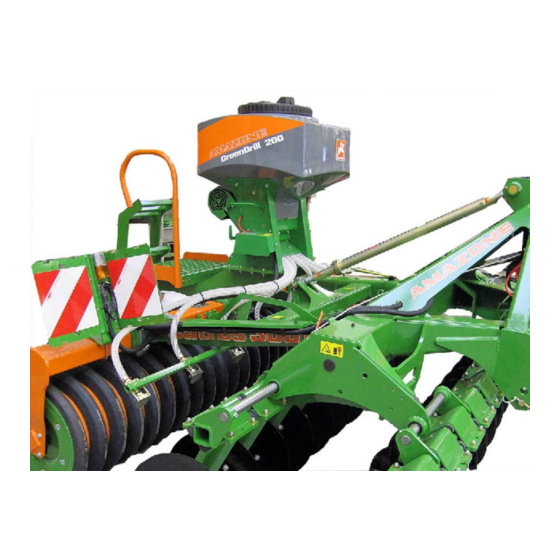
Product description Product description (1) Hopper (2) Dosing unit with sowing shaft (3) Electric motor for sowing shaft drive (4) Seed delivery hose GreenDrill BAH0054-4 02.13... -
Page 20: Intended Use
The catch crop top mounted seed drill GreenDrill is intended for conventional use in farming and serves for metering and spreading of seeds. AMAZONE machines that can be combined with the GreenDrill versions 200-E and 500-H are listed in the following table. -
Page 21: Rating Plate And Ce Mark
Product description Rating plate and CE mark The rating plate shows: Machine ID No. Type Basic weight (kg) Max. load, kg Factory The CE mark on the machine indicates compli- ance with the stipulations of the valid EU directives. Location of the rating plate (1) on the machine of the CE mark (2) on the machine. -
Page 22: Structure And Function
Structure and function Structure and function The GreenDrill catch crop seed drill is used for spreading catch crops and resowing grass seed. The seed dosed by the seeding wheels is conveyed into the seed hoses (1). The seed is placed within the range of the soil tools. -
Page 23: Metering
Structure and function Metering Each seed wheel is made up of several smaller units. The fine seed metering wheel is composed of one fine seed metering wheel (f) three wheels with 0-sowing capacity (fb) (wheels with 0-sowing capacity do not dose seed) In this combination, the seed wheel has the designation "fb-f-fb-fb". - Page 24 Structure and function The sowing shaft is made up of several identical seed wheels. The sowing shaft for fine seeds is composed of 8 seed wheels (fb-f-fb-fb). The sowing shaft for normal seeds is composed of 8 seed wheels (GGG). An electric motor drives the sowing shaft.
- Page 25 Structure and function Always carry out a calibration test on initial operation when changing the sort if the same sort is used, but of a different quality and specific weight after changing the sowing shaft if the hopper empties faster/more slowly than expected. The actual spread rate then does not correspond to the spread rate determined in the calibration test.
-
Page 26: Mechanical Adjustments
Mechanical adjustments Mechanical adjustments WARNING Before working on the machine Position the machine on a firm, horizontal surface. Secure the tractor with the attached machine against unin- tentional start-up and rolling. Removing/installing the sowing shaft 1. Empty the hopper. 2. Remove the cover (1). 3. -
Page 27: Scraper
Mechanical adjustments Scraper An adjustable scraper is attached above the sowing shaft. The scraper can be adjusted using a lever (1) on a scale of +4 to -5. Adjusting the lever allows finer dosing of the seed spread rate. Scale values -1 to -5: The scraper is pressed against the sowing shaft using the lever. -
Page 28: Agitator Shaft
Mechanical adjustments Agitator shaft Only allow the agitator shaft to run when using seeds which tend towards bridging are very light, e.g. grass. If the agitator shaft is not required, remove the 0- ring (1). The agitator shaft is driven by the sowing shaft via the 0-ring. -
Page 29: Preparing The Machine For A Calibration Test Or For Emptying The Hopper
Mechanical adjustments Preparing the machine for a calibration test or for emptying the hopper Before climbing onto the loading board Switch off the on-board computer Switch off the tractor's universal joint shaft, apply the parking brake, shut down the tractor engine and remove the ignition key Wait until the tines of the rotary harrow (rotary cultivator) have come to a standstill. -
Page 30: Use Of The Machine
Use of the machine Use of the machine Risk of crushing, cutting, being trapped or drawn in, or impact through inadequate roadworthiness and operational safety. Before starting up the machine and tractor, always check their roadworthiness and operational safety. WARNING When using the machine, observe the safety instructions in this operating manual in the operating manual of the base machine. -
Page 31: Filling The Hopper
Use of the machine Filling the hopper Before climbing onto the loading board Switch off the on-board computer Switch off the tractor's universal joint shaft, apply the parking brake, shut down the tractor engine and remove the ignition key Wait until the tines of the rotary harrow (rotary cultivator) have come to a standstill. The hopper cover has a threaded seal. -
Page 32: Greendrill 3.2 On-Board Computer
GreenDrill 3.2 on-board computer GreenDrill 3.2 on-board computer Scope of delivery (1) GreenDrill 3.2 on-board computer (2) Bracket for on-board computer (3) Power cable (3.1) for 3-pin tractor standard socket ) for battery connection (optional). Housing components (1) 3-pin plug-in connection for power supply (2) 6-pin plug-in connection. -
Page 33: Control Elements
GreenDrill 3.2 on-board computer Control elements (1) Display (6) Switch sowing shaft on/off (2) On/Off button (7) LED lights up when the sowing shaft is running (3) LED lights up when the machine is switched (8) Increase sowing shaft speed (4) Switch blower fan on/off (9) Decrease sowing shaft speed (Taste bei hydraulischem Gebläseantrieb... -
Page 34: Commissioning
GreenDrill 3.2 on-board computer Commissioning 1. Press the button the machine is switched on the LED above the button lights up The display shows the previously set sowing shaft speed (in %). The sowing shaft motor and blower fan motor do not rotate. Determining the sowing shaft speed for the first calibration test Read the sowing shaft speed for the first calibration test from the sowing table (see Appendix). -
Page 35: Calibration Test
GreenDrill 3.2 on-board computer Select the seed wheel combination so that the sowing shaft speed ideally lies between 20% and 80%. This ensures good readjustment and homogenous seed conveyance even at very low or high speeds (only with speed-dependent spread- ing). -
Page 36: Field Use - Starting Work
GreenDrill 3.2 on-board computer Field use - starting work Do not switch off the blower fan during use. Before starting work 1. Close the hopper cover. 2. Check that the baffle plates are evenly distributed 3. Check that the seed delivery hoses drop downwards along the entire length. Starting work 1. -
Page 37: Turning At End Of The Field
GreenDrill 3.2 on-board computer Turning at end of the field 1. Press and hold the button until the green LED goes out the sowing shaft stops the blower fan continues to run. 2. Lift the base machine and turn. 3. After turning the machine, press the button the sowing shaft rotates, sowing begins. -
Page 38: On-Board Computer - Installation And Connections
GreenDrill 3.2 on-board computer 6.11 On-board computer - installation and connections 6.11.1 On-board computer - installation in the tractor cab Fasten the bracket in the tractor cab with two screws. Bend the bracket so as to provide optimum reading of the display. 6.11.2 On-board computer - electrical connections Store the spare cable in the cab. -
Page 39: Faults
GreenDrill 3.2 on-board computer 6.12 Faults WARNING Risk of crushing, shearing, cutting, being caught and/or drawn in, or impact through Unintentional lowering of the machine raised using the tractor's three-point hydraulic system. Unintentional lowering of raised, unsecured machine parts. Unintentional start-up and rolling away of the tractor- machine combination. -
Page 40: Greendrill 5.2 On-Board Computer
GreenDrill 5.2 on-board computer GreenDrill 5.2 on-board computer Scope of delivery (1) GreenDrill 5.2 on-board computer (2) Bracket for on-board computer (3) Power cable (3.1) for 3-pin tractor standard socket for the battery connection (optional). Housing components (1) 3-pin plug for power supply (3) 30A fuse (2) 6-pin signal plug. -
Page 41: Control Elements
GreenDrill 5.2 on-board computer Control elements (1) Graphic display (6) Switch sowing shaft on/off (2) On/Off button (7) LED lights up when the sowing shaft is running (3) LED lights up when the machine is switched (8) Increase sowing shaft speed (4) Switch blower fan on/off (9) Decrease sowing shaft speed (Taste bei hydraulischem Gebläseantrieb... -
Page 42: Display
GreenDrill 5.2 on-board computer Display 7.4.1 Main menu display Main menu for operation without speed sensor Display of set sowing shaft speed (SW in %). Set the desired sowing shaft speed using buttons. Set the tractor speed [km/h] in the Calibration test menu or the Area calculation menu. -
Page 43: Submenu Display
GreenDrill 5.2 on-board computer 7.4.2 Submenu display Calling up submenus Call up the desired menu using the buttons. buttons are used to move around within the menu. Before entering data, call up the data entry mode using the button. Set the data using the buttons. -
Page 44: Commissioning
GreenDrill 5.2 on-board computer Commissioning 7.5.1 Start display 1. Press the button the machine is switched on the LED above the button lights up Switch-on message during switch-on process. The switch-on message shows the machine and software ver- sions. This information is used for diagnostic inspection in the event of faults. -
Page 45: Calibration Test Without Sowing Table
GreenDrill 5.2 on-board computer 7.5.2.1 Calibration test without sowing table 1. Prepare the machine for the calibration test (fit the chute, see above). 2. Check that the correct sowing shaft has been fitted. 3. Fill the hopper. 4. Call up the Calibration test menu. 5. - Page 46 GreenDrill 5.2 on-board computer 10. Weigh the calibrated seed and enter the value [kg] in the on- board computer. The required sowing shaft speed is calculated automatically. If this changes the sowing shaft speed by more than the adjacent display appears the calibration test has to be repeated.
-
Page 47: Area Calculation
GreenDrill 5.2 on-board computer 7.5.3 Area calculation Area calculation is carried out using the values from the calibration test begins as soon as the sowing shaft starts to rotate is carried out using the "actual" travel speed values (when 7-pin signal plug is connected). The following are displayed: the total area [ha] the part area [ha]... -
Page 48: Calibrating The Working Speed
GreenDrill 5.2 on-board computer 7.5.4 Calibrating the working speed The on-board computer requires the calibration value "working speed" for the speed calculation calculation of the sowing shaft speed area calculation. Calibration can be carried out by travelling a test track manual calibration. -
Page 49: Calibration (Working Speed) By Comparing The Speedometer
GreenDrill 5.2 on-board computer 7.5.4.2 Calibration (working speed) by comparing the speedometer 1. Confirm the screen display with the button. 2. Start the tractor for the calibration run. During the calibration run, compare the speeds shown in the tractor's display and speedometer. Correct the value using the buttons, until both val- ues are the same. -
Page 50: Emptying The Hopper
GreenDrill 5.2 on-board computer 7.5.5 Emptying the hopper 1. Prepare the machine for emptying the hopper (see above). 2. Call up the menu. 3. Press the button. The sowing shaft motor turns at maximum speed (without blower fan). The process can be terminated at any time by pressing the button or button. -
Page 51: Messages
GreenDrill 5.2 on-board computer Messages 7.6.1 Control messages Fault message Fault description Fault elimination The internal control voltage is Contact the Service Department. below a minimum value. The operating voltage is too low. Minimise the consumers, check the battery, check the cables, check the alternator. -
Page 52: Fault Messages
GreenDrill 5.2 on-board computer Fault message Fault description Fault elimination The travel speed is too low. Compare the set speed with the actual speed travelled. Increase travel speed. Brief display when the On/Off button is pressed when switching off the device. 7.6.2 Fault messages Fault message... - Page 53 GreenDrill 5.2 on-board computer Fault message Fault description Fault elimination Display when there is uncon- Check the cables and plugs. nected or faulty cabling. If the motor is connected and Contact the Service Depart- not overloaded, but still does ment. not rotate.
-
Page 54: On-Board Computer - Installation And Connections
GreenDrill 5.2 on-board computer On-board computer - installation and connections 7.7.1 On-board computer - installation in the tractor cab Fasten the bracket (1) in the tractor cab with two screws. Bend the bracket so as to provide optimum reading of the display. 7.7.2 On-board computer - Power supply Store the spare cable in the cab. -
Page 55: Cable Set With 3-Pin Standard Socket For The Battery Connection
GreenDrill 5.2 on-board computer 7.7.2.2 Cable set with 3-pin standard socket for the battery connection The cable set (optional) with 3-pin standard socket is used for power supply if the tractor has no 3-pin standard socket. The cable ends are screwed directly onto the battery poles. -
Page 56: 7-Pin Tractor Signal Socket
GreenDrill 5.2 on-board computer 7.7.3.1 7-pin tractor signal socket The tractor is equipped with the 7-pin tractor signal socket supplies the required 3 signals Signal cable (1) connects the on-board computer (12 -pin signal connector) to the tractor socket (7 -pin socket). The cable carries 3 signals (see Chapter "ISO 11786 Signal") from the tractor to the on-board computer. -
Page 57: Radar Sensor And Working Position Sensor Connections
GreenDrill 5.2 on-board computer 7.7.3.3 Radar sensor and working position sensor connections Requirement: The tractor does not have a 7-pin tractor signal socket. The following are subsequently mounted the radar sensor (for the travel speed) the working position sensor The splitter (A) connects the on-board computer (12-pin) to the radar sensor to the working position sensor... -
Page 58: Programming (Customer Service)
GreenDrill 5.2 on-board computer Programming (Customer service) Switch off the blower fan motor and sowing shaft motor. Open/edit the programme menu Call up the programme menu by simultaneously pressing buttons Buttons are used to move around within the menu. Change the parameters using the buttons. -
Page 59: Wheel Sensor
GreenDrill 5.2 on-board computer 7.8.3 Wheel sensor Set whether the tractor's speed sensor is being used: YES, NO or AUTO To automatically detect whether or not the speed sensor of the tractor is being used, set the on-board computer to AUTO. Make settings with the buttons. -
Page 60: Radar
GreenDrill 5.2 on-board computer 7.8.5 Radar The on-board computer works with or without radar: YES, NO or AUTO Make settings with the buttons. 7.8.6 Lifting gear sensor The on-board computer works with or without lifting gear sensor: YES, NO or AUTO Make settings with the buttons. -
Page 61: Sowing Shaft Drive Motor
GreenDrill 5.2 on-board computer 7.8.8 Sowing shaft drive motor Set which sowing shaft drive motor is connected: P8 motor (for GreenDrill with 8 outlets) P16 motor (for GreenDrill with 16 outlets). Make settings with the buttons. 7.8.9 Pressure sensor Set whether the hydraulically driven blower fan is equipped with a pressure sensor which measures the air current: JA (yes) NEIN (no) -
Page 62: Cleaning, Maintenance And Repairs
Cleaning, maintenance and repairs Cleaning, maintenance and repairs WARNING Risk of crushing, shearing, cutting, being caught and/or drawn in, or impact through Unintentional lowering of the machine raised using the tractor's three-point hydraulic system. Unintentional lowering of raised, unsecured machine parts. Unintentional start-up and rolling away of the tractor- machine combination. -
Page 63: Cleaning
Cleaning, maintenance and repairs Cleaning 1. Empty the hopper and dosing unit. 2. Dismantle the sowing shaft to enable intensive cleaning of the dosing unit. 3. Blow out the hopper and dosing unit with compressed air or dry clean it with a paintbrush. 4. -
Page 64: Sowing Tables
Sowing tables Sowing tables Forage rye Spread rate Barley Spread rate Wheat Spread rate Sowing Sowing shaft Sowing shaft shaft speed kg/min kg/min. kg/min. kg/min. kg/min. speed [%] speed [%] 0.46 0.18 0.54 0.13 0.52 0.99 0.48 0.87 0.16 1.18 1.87 0.97 1.41... - Page 65 Sowing tables Buckwheat Spread rate Oats Spread rate Rapeseed Spread rate Sowing Sowing shaft Sowing shaft shaft speed kg/min kg/min kg/min kg/min kg/min kg/min speed [%] speed [%] 0.09 0.54 0.01 0.15 0.18 0.11 0.39 0.99 0.02 0.46 0.588 0.211 0.90 1.74 0.04...
- Page 66 Sowing tables Fodder Mustard Spread rate radish Spread rate Phacelia Spread rate Sowing shaft Sowing shaft Sowing shaft kg/mi kg/min kg/min kg/min kg/min speed [%] speed [%] speed [%] 0.04 0.33 0.24 0.66 0.14 0.34 0.15 0.75 0.62 1.18 0.31 0.77 0.33 1.45...
- Page 67 Sowing tables Grass Spread rate Lupins Spread rate Alfalfa Spread rate Sowing Sowing shaft Sowing shaft shaft speed kg/min. kg/min. kg/min kg/min kg/min speed [%] speed [%] 0.06 0.27 0.42 0.10 0.30 0.22 0.61 1.11 0.21 0.70 0.49 1.17 2.26 0.40 1.38 0.76...
- Page 68 Sowing tables Red clover Spread rate Vetches Spread rate Poppy seed Spread rate Sowing Sowing shaft Sowing shaft shaft speed kg/min kg/min kg/min kg/min kg/min speed [%] speed [%] 0.04 0.56 0.76 3.37 0.029 0.15 1.37 1.42 3.89 0.049 0.33 2.72 2.51 4.75...
- Page 70 Phone: +49 5405 501-0 D-49202 Hasbergen-Gaste Fax: +49 5405 501-234 Germany e-mail: amazone@amazone.de http:// www.amazone.de Branch plants: D-27794 Hude D-04249 Leipzig F-57602 Forbach Branches in England and France Manufacturers of mineral fertiliser spreaders, field sprayers, seed drills, soil cultivation machines,...
Need help?
Do you have a question about the GreenDrill 200-E and is the answer not in the manual?
Questions and answers