Table of Contents
Advertisement
Quick Links
Advertisement
Table of Contents

Related Manuals for KUST Elektronik MM Series

Summary of Contents for KUST Elektronik MM Series
- Page 1 MM Series DC Resistance Meters - Operation Manual OPERATION MANUAL MM SERIES DC RESISTANCE METERS MM2010 MM2020 MM2030 MM2040 KUST Elektronik GmbH Am Weinberg 2 D-35619 Braunfels Germany Tel: +49 (0) 64414471223 www.kust-elektronik.com E-mail:info@kust-elektronik.com...
-
Page 2: Table Of Contents
MM Series DC Resistance Meters - Operation Manual Content: Chapter 1 Unpacking and Preparation ..........................3 1.1 Checking the Shipment ............................3 1.2 Power connection ............................... 3 1.3 The Fuse ................................3 1.4 Operating Environment ............................3 1.5 Test fixture ................................. 4 1.6 Accuracy guarantee ............................ -
Page 3: Chapter 1 Unpacking And Preparation
MM Series DC Resistance Meters - Operation Manual Chapter 1 Unpacking and Preparation This chapter describes some of the tests that must be carried out after you receive the instrument, and the conditions to be understood before the installation and use of the instrument. -
Page 4: Test Fixture
1.5 Test fixture Please use the test fixture or the test leads supplied by “KUST Elektronik GmbH”. You must keep the test fixture, the test leads and the pins of the DUT clean, so that the test device can be contact the test fixture in best possible way. -
Page 5: Additional Features
MM Series DC Resistance Meters - Operation Manual of the standard resistance wire. 1.7 Additional Features (1) Power consumption: ≤30VA. (2) Dimensions (W * H * D): 240mm * 100mm * 345mm; (foot support height included) (3) Weight: about 3kg... -
Page 6: Chapter 2 Panel Description And Basic Operation
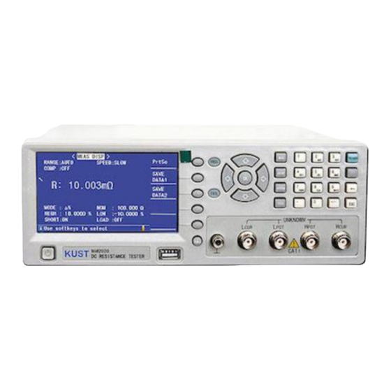
This series of instruments have a variety of configurations, see appendix. 2.1 Front Panel Figure 2-1 shows the brief description of the MM SERIES front panel. Figure 2-1 the front panel Power on/off Instrument type plate. -
Page 7: Rear Panel
MM Series DC Resistance Meters - Operation Manual 2.2 Rear Panel Figure 2-2 shows the brief description of the MM Series rear panel. Figure 2-2 the rear pane 1) RS232C Interface Connector This is the RS232C interface connector used when operating on the serial interface is used. -
Page 8: Format Of Data Storage
MM Series DC Resistance Meters - Operation Manual 2.4 Format of data storage When you use the USB to save the data in the measurement page using the TOOLS key, there will be two kinds of saving data mode. The basic form is as follows: <A>, <COMP>... -
Page 9: Stats Disp> Discription
MM Series DC Resistance Meters - Operation Manual 3.2 <STATS DISP> Description The function is not standard. Only “STATS” in this page can be operated: ON, OFF, RESET. The page displays the parameters and state as follows: R: measurement results, do not support the% deviation display mode. -
Page 10: Meas Setup> Discription
MM Series DC Resistance Meters - Operation Manual 3.3 <MEAS SETUP> Description The page can be set as follows: MEAS SETUP:MEAS SETUP, CORR SETUP, T SETUP (nonstandard). AVERAGE:INCR+、DECR-,or enter a value in the 1~255 by the numeric keys (default 1). -
Page 11: Temp Setup> Discription
MM Series DC Resistance Meters - Operation Manual When using KA1002, the following figure is shown below. The two test lines are connected to the red clip, which is labeled with a red sleeve for Hcur, the other is Hpot; the upper two is connected to the black clip, which is marked by black Lcur, the other is Lpot. - Page 12 MM Series DC Resistance Meters - Operation Manual ❖ t and αt are used for TC. :enter the value of the -10~99.9 within the digital key(℃) :enter the value of the -10~99.9 within the digital key(ppm) αt Temperature compensation formula is as follows: *{1+α...
-
Page 13: System Setup> Discription
MM Series DC Resistance Meters - Operation Manual :The temperature coefficient of the soft copper wire at 20℃ is 3930ppm α According to the calculated K is close to the value of the copper in the IEC standard: 235。 ❖ V1, T1, V2 and T2 used for AnLG_IN. -
Page 14: Comm Setup> Discription
MM Series DC Resistance Meters - Operation Manual ❖ password: Lock system: including file protection and boot password. Lock file: file protection. Change Password: change password. Factory default password for example: 2517, 2518 and so on (by the instrument model). -
Page 15: Files Setup> Discription
MM Series DC Resistance Meters - Operation Manual 3.9 < FILES SETUP> Description Press “FILE” to enter < INTER Files List > page Figure 3-9-1 Press “FILE” again to change INT/EXT . Figure 3-9-2 File operation steps: A. Refer to the existing file 1) use direction key to check files 2) input the corresponding serial number of files, then press “OK”... -
Page 16: Chapter 4 Performance Parameter
MM Series DC Resistance Meters - Operation Manual Chapter 4 performance parameter 4.1 Accuracy of measurement 1) Resistance Accuracy test environment: 18 ℃to 28 ℃, RH: below 75%, test conditions: slow. For MM2010, see then table below: 20 mΩ 2 Ω... -
Page 17: Measurement Speed
MM Series DC Resistance Meters - Operation Manual ❖ When the temperature sensor uses analog input Note: the method of temperature precision conversion: Temperature refer to 1V; T : Temperature refer to 0V; T : current temperature When the temperature is 0℃~18℃ and 28℃~40℃, Temperature coefficient is ( 0.1% rdg ±0.3mV)/°C... -
Page 18: Handler Application
MM Series DC Resistance Meters - Operation Manual Timing of interface signal: 5.2 HANDLER Application • Users can refer to the following circuit connection when the external voltage is used, the EXTV (5~24V) is the external power supply for the user, COM is the external power supply,... -
Page 19: Handler Custom With Optocoupler Output
MM Series DC Resistance Meters - Operation Manual 5.3 HANDLER Custom with optocoupler output The instrument panel will be labeled " optocoupler ", see below: EXTV (5~24V) provide with external power supply, COM is the external ground. -
Page 20: Chapter 6 Appendix
MM Series DC Resistance Meters - Operation Manual Chapter 6 Appendix (1) characteristics of metals and alloys Electrical conductivity of copper wire: Because the change of temperature coefficient is based on temperature and electrical conductivity, the temperature coefficient is calculated according to the formula:...
Need help?
Do you have a question about the MM Series and is the answer not in the manual?
Questions and answers