Table of Contents

Related Manuals for KUST Elektronik PT5020

Summary of Contents for KUST Elektronik PT5020
- Page 1 PT5020 & PT5030 Operation Manual Operation Manual KUST Elektronik GmbH PT5020 & PT5030 Impulse Winding Tester KUST Elektronik GmbH Friedenstraße 26 D-35578 Wetzlar Germany E: info@kust-elektronik.com P: +49 (0) 64414471223...
-
Page 2: Table Of Contents
PT5020 & PT5030 Operation Manual Contents Chapter 1 Overview ......................... 1-1 1.1 Production introduction ....................1-2 1.2 Operation environment ..................... 1-3 1.2.1 Power supply ......................1-3 1.2.2 Environment temperature and humidity ..............1-3 1.2.3 Warm-up ......................... 1-3 1.3 Dimensions and weight ..................... 1-3 Chapter 2 General specifications ..................... - Page 3 PT5020 & PT5030 Operation Manual 5.2.5 Volt ADJ ......................... 5-3 5.2.6 Wave Disp ......................5-3 5.2.7 Trig Mode ....................... 5-4 5.2.8 Delay Time ......................5-4 5.2.9 BDV Test ........................ 5-4 5.2.10 Start Volt ......................5-5 5.2.11 End Volt ....................... 5-5 5.2.12 Volt Step .......................
- Page 4 PT5020 & PT5030 Operation Manual 7.2.2 Sample test for standard wave ................7-1 7.3 BDV test ........................... 7-2 7.4 Technology application ..................... 7-2 7.4.1 Test objects ......................7-2 7.4.2 Select comparison method ..................7-3 7.4.3 Settings of comparison method ................7-3 7.4.4 Select standards ......................
- Page 5 PT5020 & PT5030 Operation Manual 10.2 Warranty ........................10-1...
-
Page 6: Chapter 1 Overview
PT5020 & PT5030 Operation Manual Chapter 1 Overview Thank you for your Choosing one of our products. Before the use of it, please locate the items listed in this manual to ensure nothing is missing. If in the case that any item is missing, please contact us immediately. -
Page 7: Production Introduction
PT5020 & PT5030 Operation Manual poor ventilation. In addition, the instrument will generate high voltage, so it must be used at room temperature and in the absence of much dust. 1.1 Production introduction Due to the influence of wire material, magnetic material, framework and manufacture technics, winding products such as transformers, motor windings may have defects of low insulation between winding layers, circles and leads. -
Page 8: Operation Environment
PT5020 & PT5030 Operation Manual Figure 1-2 Typical self-attenuation oscillation wave 1.2 Operation environment 1.2.1 Power supply Voltage: 198V-242V AC, 99V-121V AC Power frequency: 47.5Hz-63Hz Consumption: ≤50VA 1.2.2 Environment temperature and humidity Normal working temperature: 0°~40°, Humidity: ≤ 90%RH Referential working temperature: 20°±8°, Humidity: ≤ 80%RH Transferring environment temperature: 0°~50°, Humidity: ≤... -
Page 9: Chapter 2 General Specifications
PT5020 & PT5030 Operation Manual Chapter 2 General specifications Chapter 2 General specifications Specifications Specifications PT5020 PT5030 Output for impulse voltage 100V~3000V 100V~5000V 10V steps 10V steps 5%±10V 5%±20V Inductance test range >10µH >10µH Impulse energy Max 250milli-Joules Max 250 milli-Joules... -
Page 10: Comparison Methods
PT5020 & PT5030 Operation Manual Chapter 2 General specifications Beeper alarm Beep mode ON (adjust for high and low tone), OFF Memory Built-in memory: 100 files USB disk memory Interface HANDLER (START, STOP, PASS, NG, BUSY, EOC, etc.) RS232C USB Device USB Host Comparison methods 2.2.1... -
Page 11: Corona Discharge Comparison
PT5020 & PT5030 Operation Manual Chapter 2 General specifications Figure 2-2 Differential Area Comparison The differential area size reflects the value of inductance and total energy loss. This method is especially effective to detect the differences of inductance L between the standard winding and the tested winding. -
Page 12: Differential Phase Comparison
PT5020 & PT5030 Operation Manual Chapter 2 General specifications 2.2.4 Differential phase comparison User can specify a zero-crossing point to compare. The instrument will judge the zero-crossing offset between the tested waveform and standard waveform and then compare the oscillation period between the two waveforms. -
Page 13: Chapter 3: Panels And Display
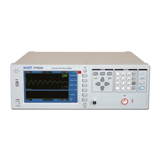
PT5020 & PT5030 Operation Manual Chapter 3 Panels and display Chapter 3: Panels and display Front panel Serial Number Name Instruction Buzzer window USB HOST interface Connect U flash disk so as to save or use a specified file Brand and model 840×480... - Page 14 PT5020 & PT5030 Operation Manual Chapter 3 Panels and display and zone on LCD display page. When cursor moves to some zone, the zone displays with reverse on LCD. Press this key to enter into the system setup [SYSTEM] page.
-
Page 15: Rear Panel
PT5020 & PT5030 Operation Manual Chapter 3 Panels and display 3.2 Rear panel HA N D LER FO O T. C RS- 232C LA N W A RN I N G : Thi s i ns t r um ent cont ai ns no oper at or s er vi ceabl e par t s i ns i de;... -
Page 16: Introduction To Display Area
PT5020 & PT5030 Operation Manual Chapter 3 Panels and display Introduction to display area Specific definition for each area: Voltage/div Show the voltage of every grid Waveform display area In this area, test and standard waveforms, peaks of impulse voltage and comparison results are displayed. - Page 17 PT5020 & PT5030 Operation Manual Chapter 3 Panels and display Four comparison results and their final display results Information Show the state of interface selecting, availability of U disk, key lock, etc. 10 Function zones of soft keys Show the corresponding function and parameter of each soft key.
-
Page 18: Chapter 4 Introduction To [Disp]
PT5020 & PT5030 Operation Manual Chapter 4 Introduction to [DISP] Chapter 4 Introduction to [DISP] Press the DISP menu key to enter the < MEAS DISP> page (the default page). In this page, measurements are taken and the test waveform is displayed. Some function settings such as standard sampling (Standard), comparison setting (Compare), measurement function (Measure), auxiliary function (Utility), statistic function (Statistics), sampling rate, etc. -
Page 19: Standard Sampling
PT5020 & PT5030 Operation Manual Chapter 4 Introduction to [DISP] " Compare Enter the Compare setup submenu. Under this menu, states of the four compare methods, compare parameters can be set. " Measure Enter the Compare function submenu. Under this menu, wave voltage, wave time, wave frequency can be set. -
Page 20: Compare
PT5020 & PT5030 Operation Manual Chapter 4 Introduction to [DISP] 4.3.1.3 LOOP The instrument starts to sample standard waveforms, change frequency, and cycle sampling. " Select Select the sample waveform at the current frequency as the standard waveform. " Select & Check... -
Page 21: Measure
PT5020 & PT5030 Operation Manual Chapter 4 Introduction to [DISP] Diff " Lighten the icon to enable the cursor key and change the 2.0% differential value. " " Return to previous page. 4.3.2.2 DIFF ZONE Method Select the differential area size comparison method. All setup DIFF ZONE operations are the same as those of AREA SIZE. -
Page 22: Utility
PT5020 & PT5030 Operation Manual Chapter 4 Introduction to [DISP] 4.3.4 Utility Utility function is used to set parameters displayed in the waveform display zone. " Scale Adj Lighten the icon. Use the soft key to enlarge the waveform display scale ranging from 1 to 3 times. -
Page 23: Chapter 5 Introduction To [Setup]
PT5020 & PT5030 Operation Manual Chapter 6 Introduction to [SYSTEM] Chapter 5 Introduction to [SETUP] Press SETUP to enter the <Setup> page. Introduction to icons of soft keys " Coarse adjustment key used to increase the selected value. " Coarse adjustment key used to decrease the selected value. -
Page 24: Imp Volt
PT5020 & PT5030 Operation Manual Chapter 6 Introduction to [SYSTEM] " Wave display (Wave Disp) " Trigger mode (Trig Mode) " Delay time (Delay Time) " Breakdown voltage test (BDV Test) " Breakdown impulse(BDV Imp) " Start voltage(Start Volt) "... -
Page 25: Erase Imp
PT5020 & PT5030 Operation Manual Chapter 6 Introduction to [SYSTEM] used to terminate inputting. 5.2.4 Erase Imp The number of erase impulses can be set from 0 to 16. Move the cursor to this zone, following soft keys will be displayed. -
Page 26: Trig Mode
PT5020 & PT5030 Operation Manual Chapter 6 Introduction to [SYSTEM] 5.2.7 Trig Mode The instrument will perform a measurement only at the receipt of a trigger signal. PT50xx provides four kinds of trigger mode: MAN (manual including foot control), EXT (external), INT (internal) and BUS. -
Page 27: Start Volt
PT5020 & PT5030 Operation Manual Chapter 6 Introduction to [SYSTEM] 5.2.10 Start Volt Start Volt ranges from 100V to 3000V(or 5000V) but cannot be larger than End Volt. Move the cursor to this zone, following soft keys will be displayed. -
Page 28: Position(Phase Diff
PT5020 & PT5030 Operation Manual Chapter 6 Introduction to [SYSTEM] # $ They are fine adjustment soft keys used to change the value of position by 10. " 5.2.15 Position(PHASE DIFF) Set the zero-crossing position for PHASE DIFF that is to select a zero-crossing position for the comparison of phase difference. - Page 29 PT5020 & PT5030 Operation Manual Chapter 6 Introduction to [SYSTEM] Figure 5-2 Internal File Int. File consists of file number (NO), file name (File), Date/ Time, Load. Following soft keys can be used in this page. " Load Press this key to load a file stored in the internal non-volatile memory. As figure 5-2 indicates, using the arrow key select the needed file.
-
Page 30: Ext. File
PT5020 & PT5030 Operation Manual Chapter 6 Introduction to [SYSTEM] ! Enter rules: Pressing a numeric key, the corresponding letters or characters will be displayed on the screen. If user wants to input a number, the numeric key should be pressed again. While a letter or character is needed, then the soft key corresponding to the letter or the character should be pressed. - Page 31 PT5020 & PT5030 Operation Manual Chapter 6 Introduction to [SYSTEM] default name ranges from FOLDER01 to FOLDER 99. " Save Press this key to save a file. Move the arrow key to choose the catalog storing the file. Press the Save soft key and then enter the file name.
-
Page 32: Chapter 6 Introduction To [System]
PT5020 & PT5030 Operation Manual Chapter 6 Introduction to [SYSTEM] Chapter 6 Introduction to [SYSTEM] Press SYSTEM to enter System. 6.1 System Figure 6-1 shows the System page. Figure 6-1 System Parameters irrelevant to test performance can be set in this page. -
Page 33: Brightness
PT5020 & PT5030 Operation Manual Chapter 6 Introduction to [SYSTEM] 6.1.1 Brightness Move the cursor to this zone, following soft keys will be displayed. # $ They are soft keys used to increase and decrease the LCD display. " 6.1.2 Pass/Fail Move the cursor to this zone, following soft keys will be displayed. -
Page 34: Language
PT5020 & PT5030 Operation Manual Chapter 6 Introduction to [SYSTEM] " Turn off the password function. When user turns on or unlocks the instrument, it is not required to input password. Note: When turning off the password function, it is required to input the password. -
Page 35: I/O
PT5020 & PT5030 Operation Manual Chapter 6 Introduction to [SYSTEM] LAN interface and interface setups can be set, as shown in figure 6-2. Figure 6-2 Interface 6.2.1 I/O Move the cursor to the I/O: zone, following soft keys will be displayed. - Page 36 PT5020 & PT5030 Operation Manual Chapter 6 Introduction to [SYSTEM] table. Signal Code Connector pin number Transmitted data Received data Signal ground common Table 6-1 RS-232 signal and pin number The reason is that the use of three lines is much more inexpensive and much simpler than that of five lines or six lines, which is the biggest advantage of using serial interface for communication.
-
Page 37: Usb Interface
PT5020 & PT5030 Operation Manual Chapter 6 Introduction to [SYSTEM] " 1 Bit Set the stop bit to1 bit. " 1.5 Bit Set the stop bit to 1.5 bit. " 2 Bit Set the stop bit to 2 bit. 6.2.2.4 Parity Move the cursor to this zone, following soft keys can be used. - Page 38 PT5020 & PT5030 Operation Manual Chapter 6 Introduction to [SYSTEM] Figure 6-5 USBCDC has been installed Now, usb VCom port acts as a serial port. When PC has no serial port, the communication software based on this serial port can be used as USB virtual serial port.
-
Page 39: About
PT5020 & PT5030 Operation Manual Chapter 6 Introduction to [SYSTEM] 6.3 About The About page shows some relevant information of the instrument, such as Model Number, Firmware Version, System Version. There are three soft keys available: Reset, Factory, Firmware update. Figure 6-11 shows the About page. -
Page 40: Chapter 7 User Guide
PT5020 & PT5030 Operation Manual Chapter 7 User guide Chapter 7 User guide 7.1 Use of keys 7.1.1 Switch the display page There are three function pages displayed on the instrument: MEAS, STEUP and SYSTEM. MEAS Press this key to enter the measurement display page. -
Page 41: Bdv Test
PT5020 & PT5030 Operation Manual Chapter 7 User guide 7.3 BDV test Determine an impulse voltage appropriate to test. The applied voltage has little effect on the turn-to-turn short test and the layer-to-layer short test of coil, but the amplitude of the applied impulse voltage has a great impact on the insulation test of coil. -
Page 42: Select Comparison Method
PT5020 & PT5030 Operation Manual Chapter 7 User guide 7.4.2 Select comparison method Area size comparison is mainly used to compare the energy consumption. Differential area comparison is sensitive to energy consumption and inductance change. Corona comparison method is the best one for testing internal insulation of the coil. -
Page 43: Select Standards
PT5020 & PT5030 Operation Manual Chapter 7 User guide switch off the test method and directly take the corona comparison method. ⑤ It is the same as A④. 7.4.4 Select standards Set test voltage. Then observe the corona value under non-standard test mode (7.2.1). -
Page 44: Chapter 8 Command Reference
PT5020 & PT5030 Operation Manual Chapter 8 SCPI Command reference Chapter 8 Command reference 8.1 Command structure PT50xx series has two types of commands: GPIB common commands and SCPI commands. The GPIB common commands are defined in IEEE std.488.2-1987, and these commands are common for all devices. - Page 45 PT5020 & PT5030 Operation Manual Chapter 8 SCPI Command reference case.) For example: COMPARATOR:AREASIZE ON = COMP:AREA ON The command header should be followed by a question mark (?) to generate a query for that command. For example: COMP:AREA? Multiple command rules: The semicolon (;) can be used as a separator to execute multiple commands on a single line.
-
Page 46: Data Format
PT5020 & PT5030 Operation Manual Chapter 8 SCPI Command reference including units. For example: disp:page meas = DISP:PAGE MEAS = DiSp:PAGe MEas 8.2 Data format PT50xx outputs the waveform data using the ASCII via the GPIB bus. The format is described as follows. -
Page 47: Command Reference
PT5020 & PT5030 Operation Manual Chapter 8 SCPI Command reference code parameter or a GPIB command. Square brackets indicate that the enclosed items are optional. When several items are enclosed by braces, one and only one of these elements may be selected. - Page 48 PT5020 & PT5030 Operation Manual Chapter 8 SCPI Command reference displayed on the LCD screen. Command syntax: DISPlay:PAGE <page name> <page name> are as follows: MEASurement sets the display page to the measurement display page (MEASurement). MSETup sets the display page to the measurement setup page (Meas SETup).
- Page 49 PT5020 & PT5030 Operation Manual Chapter 8 SCPI Command reference ALL ON ONLY STDWAVE ONLY TESTWAVE <NL^END> ALL OFF Where, ALL ON Both the standard waveform and the tested waveform are currently displayed on the screen. ONLY STDWAVE Only the standard waveform is currently displayed on the screen.
-
Page 50: Measure Function Subsystem Commands
PT5020 & PT5030 Operation Manual Chapter 8 SCPI Command reference Where, 1 (decimal49) is equal to ON; the corona display mode is ON. 0 (decimal48) is equal to OFF; the corona display mode is OFF. For example: WrtCmd( “DISP: CORONA ON” ); the current corona display mode is ON. -
Page 51: Comparator Subsystem Commands
PT5020 & PT5030 Operation Manual Chapter 8 SCPI Command reference 8.4.3 COMParator subsystem commands The COMParator subsystem commands set the compare conditions, such as Areasize, Diffzone, Corona and Phasediff. Figure 8-5 shows the command tree of the COMParator subsystem commands. - Page 52 PT5020 & PT5030 Operation Manual Chapter 8 SCPI Command reference Query syntax: COMParator[:STATe]? Return format: <NL^END> The :AREAsize[:STATe] command sets the Areasize comparator function to ON or OFF. The :AREAsize[:STATe]?query returns the current Areasize comparator state. Command syntax: COMParator:AREAsize[:STATe] Where, 1 (decimal49) is equal to ON.
- Page 53 PT5020 & PT5030 Operation Manual Chapter 8 SCPI Command reference comparator. Command syntax: COMParator:AREAsize:DIFFerence <value> Where <value> can be NR1, NR2 or NR3 format without unit. For example: WrtCmd( “COMP:AREA:DIFF 2.5” ); set the difference limit value to 2.5%. " NOTE: The <value> here is a percent value, For example, input 2.5 for2.5%.
- Page 54 PT5020 & PT5030 Operation Manual Chapter 8 SCPI Command reference The :DIFFzone:DIFFerence command sets the difference limit value of Diffzone comparator. The :DIFFzone:DIFFerence? query returns the current difference limit value of the Diffzone comparator. Command syntax: COMParator:DIFFzone:DIFFerence <value> Where, <value> can be NR1, NR2 or NR3 format without unit.
- Page 55 PT5020 & PT5030 Operation Manual Chapter 8 SCPI Command reference Query syntax: COMP:CORO:RANG? Return format: <start pot>,<end pot><NL^END> start pot,end pot are NR1 format. The :COROna:DIFFerence command sets the difference limit value of the Corona comparator. The :COROna:DIFFerence? query returns the current difference limit value of the Corona comparator.
-
Page 56: Impulse Voltage Subsystem Commands
PT5020 & PT5030 Operation Manual Chapter 8 SCPI Command reference The :PHASediff:DIFFerence command sets the difference limit value of the Phasediff comparator. The :PHASediff:DIFFerence? query returns the current difference limit value of the Phasediff comparator. Command syntax: COMParator:PHASediff:DIFFerence <value> Where, <value>... - Page 57 PT5020 & PT5030 Operation Manual Chapter 8 SCPI Command reference For example: WrtCmd( “IVOLT:VOLT 1000V” ); set the impulse voltage to 1000V. Query syntax: IVOLTtage:[VOLTage]? Return format: <NR1><NL^END> " NOTE: The query returns no unit, and the default voltage unit is V.
-
Page 58: Sample Rate Subsystem Commands
PT5020 & PT5030 Operation Manual Chapter 8 SCPI Command reference The :VADJust command sets the impulse auto adjust function to ON or OFF. The :VADJust? query returns the current state of the impulse auto adjust function. Command syntax: IVOLTage:VADJust Where,... - Page 59 PT5020 & PT5030 Operation Manual Chapter 8 SCPI Command reference The :RATE command sets the sample rate. The :RATE? query returns the current sample rate. Command syntax: SRATE:RATE <value> Where, <value> The available values are listed as follows: 200MSa/s,100MSa/s, 50MSa/s, 20MSa/s, 10MSa/s,5MSa/s, 2MSa/s, 1MSa/s,500kSa/s,...
-
Page 60: Standard Wave Subsystem Commands
PT5020 & PT5030 Operation Manual Chapter 8 SCPI Command reference For example: WrtCmd( “SRATE:EXT MIN” ); set to display all 960 points of the waveform. ! NOTE: In the process of testing, this command will be ignored. Query syntax: SRATE:EXTend?... -
Page 61: Wave Adjust Subsystem Commands
PT5020 & PT5030 Operation Manual Chapter 8 SCPI Command reference one-sample mode. The :TRIGger[:IMMediate] command is used to trigger a standard waveform measurement. Command syntax: SWAVE:TRIGger[:IMMediate] For example: WrtCmd( “SWAVE:TRIG” ); " NOTE: 1.This command is available only on the <MEAS DISP> page. -
Page 62: Statistic Subsystem Commands
PT5020 & PT5030 Operation Manual Chapter 8 SCPI Command reference Where, RIGHt Move the waveform to the right. Move the waveform to the right. LEFT Move the waveform to the left. Move the waveform to the left. The :EXTend command is used to extend the waveform. -
Page 63: Trigger Subsystem Commands
PT5020 & PT5030 Operation Manual Chapter 8 SCPI Command reference Where, 1 (decimal 49) When the function is ON 0 (decimal 48) When the function is OFF For example: WrtCmd( “STAT ON” ); turn on the statistic function. Query syntax: STATistic[:STATe]? Return format:<NR1><NL^END>... -
Page 64: Fetch?Subsystem Commands
PT5020 & PT5030 Operation Manual Chapter 8 SCPI Command reference Where, Triggered by pressing the START button or using foot control switch EXTernal Triggered by the HANDLER interface. INTernal Automatically triggered after pressing the START button. Triggered by RS232 interface, USB or LAN interface. - Page 65 PT5020 & PT5030 Operation Manual Chapter 8 SCPI Command reference will be executed after the current measurement or next measurement is finished. Refer to the previous section Data Format for the returned data format. The Comparison RESult? query returns the latest comparison result.
-
Page 66: Measure Subsystem Commands
PT5020 & PT5030 Operation Manual Chapter 8 SCPI Command reference <NR1>, <NL^END> The returned data are in turn as follows: total test times and times of PASS, total test times for Area Size comparison and times of PASS, total test times for Diff Zone comparison and times of PASS, total test times for Corona comparison and times of PASS, total times for Phase Diff comparison and times of PASS. -
Page 67: Abort Subsystem Command
PT5020 & PT5030 Operation Manual Chapter 8 SCPI Command reference will vary with the frequency range. Query syntax: MEASure:FREQuency? Return format: <start>,<end><NL^END> Both <start> and <end > are NR1 format. The :TIME command sets the time range. The :TIME? query returns the current time range. -
Page 68: Local Control Subsystem Commands
PT5020 & PT5030 Operation Manual Chapter 8 SCPI Command reference For example: WrtCmd(“MMEM:LOAD:STAT 1”); load file 1. " NOTE: 1. If the file you want to load is not available, “File not exist” message will be displayed on the system message line. -
Page 69: Common Commands
PT5020 & PT5030 Operation Manual Chapter 8 SCPI Command reference 8.4.15 Common commands PT50xx provides following common commands: *RST The *RST command is used to reset the instrument. Command syntax: *RST For example: WrtCmd( “*RST” ); *TRG The *TRG command (trigger command) triggers a measurement and writes the tested waveform data into the output buffer. - Page 70 PT5020 & PT5030 Operation Manual Chapter 8 SCPI Command reference warning messages will be displayed on the system message line. The following table shows the common error and warning messages, which will be displayed on the message line when they occur.
-
Page 71: Chapter 9 Handler Interface
PT5020 & PT5030 Operation Manual Chapter 9 Handler interface Chapter 9 Handler interface Basic information The handler interface employs a 9-pin DB connector. Pin sequence is as follow. (side view) The signal definitions for each pin are described as follows: "... -
Page 72: Electrical Characteristics
PT5020 & PT5030 Operation Manual Chapter 9 Handler interface when use. The timing diagram for handler interface is displayed in above figure, T1 is the trigger pulse width and the minimum pulse width is 1 us. T2 is the delay time, after the foregoing measurement completed to next trigger signal;... -
Page 73: Isolated Input
PT5020 & PT5030 Operation Manual Chapter 9 Handler interface Figure 9-1 Simplified diagram of the output signals A simplified diagram of the output signals is shown in Figure 9-1. * is the default jumper setting when shipped from factory. That is to say, the default jumper setting is to use external voltage source. -
Page 74: Jumper Setup On Handler Interface
PT5020 & PT5030 Operation Manual Chapter 9 Handler interface Figure 9-2 Simplified diagram of the input signal In figure 9-2, the default jumper setting is to use external voltage source. Actually, the input signals and the output signals use the external voltage source together. The Current-limit resistor is used to limit the current and the default resistor is only suitable for external voltage source range from 5V to 8V. - Page 75 PT5020 & PT5030 Operation Manual Chapter 9 Handler interface Figure 9-3 Jumper position on the Handler interface board As above figure shown, when shipped from the factory, both jumpers are set at the upper position. If you want to apply the internal power supply, you must set both jumpers at the lower position.
-
Page 76: Chapter 10 Package Contents And Warranty
10.2 Warranty This KUST Elektronik GmbH instrument product is warranted against defects in material and workmanship for a period of two years from the date of shipment. You should supply us with the warranty card before you enjoy the free maintenance service. This warranty does not apply in the event of misuse or abuse of the product or as a result of unauthorized alterations or repairs. - Page 77 PT5020 & PT5030 Operation Manual Chapter 10 Package contents and warranty NOTES: 10-2...
Need help?
Do you have a question about the PT5020 and is the answer not in the manual?
Questions and answers