
Subscribe to Our Youtube Channel
Related Manuals for Environnement MIR 9000H


Summary of Contents for Environnement MIR 9000H
- Page 1 TECHNICAL MANUAL MIR 9000H HEATED IR GAS FILTER CORRELATION MULTIGAS MONITOR - FEBRUARY 2012 - 111 bd Robespierre, 78300 POISSY - -TEL. 33(0)-1.39.22.38.00 – FAX 33(0)-1.39 65.38.08 http://www.environnement-sa.com...
- Page 2 MIR 9000H Environnement Duplication prohibited WARNING The information in this document is subject to change without notice. The designer reserves the right to upgrade his equipment without updating this document. Consequently, the information in this document is not contractual. APRIL 2011...
-
Page 3: Table Of Contents
CHAPTER 1 - GENERAL – CHARACTERISTICS GENERAL 1–3 CHARACTERISTICS 1–12 CHAPTER 2 – OPERATION INFRARED CORRELATION PRINCIPLE 2–3 PRINCIPLE APPLIED TO THE MIR 9000H 2–4 DESCRIPTION OF THE MAIN MODULES 2–7 SIMPLIFIED OPERATION FLOWCHART 2–12 CHAPTER 3 – OPERATING INSTRUCTIONS FIRST TIME RUNNING 3–5... - Page 4 MIR 9000H Environnement Duplication prohibited CHAPTER 5 – CORRECTIVE MAINTENANCE LIST OF ALARMS AND CONTROLS ADJUSTMENT AND INSPECTION OF THE MIR MODULE BOARD CONFIGURING THE BOARDS 5-13 CHAPTER 6 – APPENDIX DNP-ARM7 board APRIL 2011...
- Page 5 Figure 1–2 – Display and keyboard 1–4 Figure 1–3 – Lower panel of the MIR 9000H 1–5 Figure 1–4 – Components location of the MIR 9000H – covers ON 1–7 Figure 1–5 – Detailed view of the stepping motor and IR detector assembly 1–8 Figure 1–6 –...
- Page 6 MIR 9000H Environnement Duplication prohibited LIST OF TABLES Table 3–1 – Relays configuration 3–35 Table 3–2 – Remote controls configuration 3–36 Table 5–1 – Configuration of MODULE board 5-16 Table 5–2 – Configuration and tests points of the PILOT board 5-19 Table 5–3 –...
- Page 7 MIR 9000H Environnement Duplication prohibited INDEX OF PAGES Page Date Page Date Page Date 02.2012 3-10 04.2011 04.2011 04.2011 3-11 04.2011 04.2011 04.2011 3-12 04.2011 04.2011 04.2011 3-13 04.2011 4-10 04.2011 04.2011 3-14 04.2011 4-11 04.2011 04.2011 3-15 04.2011 4-12 04.2011...
- Page 8 MIR 9000H Environnement Duplication prohibited Page intentionally left blank 0–8 APRIL 2011...
-
Page 9: Chapter 1 - General - Characteristics
Figure 1–2 – Display and keyboard 1–4 Figure 1–3 – Lower panel of the MIR 9000H 1–5 Figure 1–4 – Components location of the MIR 9000H – covers ON 1–7 Figure 1–5 – Detailed view of the stepping motor and IR detector assembly 1–8 Figure 1–6 –... -
Page 10: Figure 1-1 - Presentation Of The Mir 9000H Analyzer
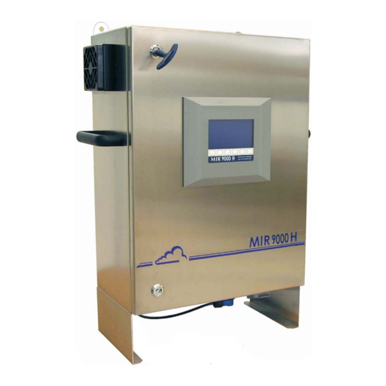
MIR 9000H Environnement Duplication prohibited GENERAL CHARACTERISTICS Figure 1–1 – Presentation of the MIR 9000H analyzer 1–2 APRIL 2011... - Page 11 1.1.1 PRESENTATION The MIR 9000H analyzer enables continuous measurement on a gaseous sample of 1 to 5 gases by infrared spectroscopy with correlation, using a gaseous filter. The principle on which this method is based is completely physical and enables specific measurement of each gas.
-
Page 12: Figure 1-2 - Display And Keyboard
Duplication prohibited 1.1.2.1 Front panel On all versions, the front panel of the MIR 9000H is fitted with: A backlit liquid crystal display (Figure 1–2) 16 lines, 40 columns (240 * 128 pixels), It provides the measurement values according to the selected unit and the information required for the programming and the checking of the analyzer. -
Page 13: Figure 1-3 - Lower Panel Of The Mir 9000H
(analog inputs/outputs, remote control input, remote signalling), (7) TCP/IP network connection, (8) electric connection of the heated line, (9) cable of electric power supply, (10) connection of the zero / span solenoid valves. Figure 1–3 – Lower panel of the MIR 9000H APRIL 2011 1–5... - Page 14 When the heated line length is below 25 m, its electrical connection can be performed directly on the analyzer. When the heated line length is within 25 and 60m, it electrical connection can be performed from an interconnection box assembled at MIR 9000H analyzer outlet and powered to 115/230V mains. 1–6...
-
Page 15: Figure 1-4 - Components Location Of The Mir 9000H - Covers On
(23) location of ARM7 calculator board, (24) location of RS4i board, (25) power static relays of the heated line, (26) counter of operating time, (27) connector block of chamber and manifold heating, (28) TCP/IP connector. Figure 1–4 – Components location of the MIR 9000H – covers ON APRIL 2011 1–7... -
Page 16: Figure 1-5 - Detailed View Of The Stepping Motor And Ir Detector Assembly
MIR 9000H Environnement Duplication prohibited (1) stepping motor and IR detector assembly, (2) filter wheel enclosure, (3) stepping motor, (4) IR detector, (5) IR source, (6) cell wheel enclosure, (7) stepping motor of the cell wheel, (8) chopper, (9) motor of chopper, (a) belt of the motor. - Page 17 Duplication prohibited 1.1.2.3 Components location For the MIR 9000H boxes, the two locks need to be unlocked (RITTAL™ key no. 3524) and the door needs to be opened to get access to the internal components. Physical and mechanical elements: The stepping motor and IR detector assembly (1) includes : ...
- Page 18 MIR 9000H Environnement Duplication prohibited 1.1.3 VARIOUS OPERATION MODES 1.1.3.1 Standard Expression of measurement values in ppm, mg/Nm or as %. Reference zero, zero and automatic calibration sequence are programmable. Integration time is automatic or programmable. Automatic checking of multiplexed parameters and correct operation tests.
- Page 19 Environnement Duplication prohibited 1.1.4 RELATED EQUIPMENT For some applications, the MIR 9000H is integrated in a "ready-for-use" system that consists of: a LCPD or HOFI sampling box, an air-conditioned analysis cabinet that consists of: A unit for conditioning and distributing compressed air (M.D.S.).
- Page 20 MIR 9000H Environnement Duplication prohibited CHARACTERISTICS 1.2.1 TECHNICAL CHARACTERISTICS ppm, mg/Nm or % Unit (programmable) , and H O (*) Gases analyzed 8 (programmable) Analog inputs 2% full scale Detectable minimum 2 % full scale on calibration bench Repeatability ...
-
Page 21: Figure 1-7 - Links Between Units
-10°C to +60°C Humidity: 0 to 95% 1.2.3 INSTALLATION CHARACTERISTICS 1.2.3.1 Links between units The MIR 9000H requires the following power supplies and external links: Remote controls / alarms of LCPD or HOFI sampling boxes Heated line of sample Sampling probe 230V-50Hz... - Page 22 1.2.3.2 Handling and storage The MIR 9000H should be handled with care in order to avoid the damaging of the various connectors and connections sticking out from the backside or the lateral side. Make sure that the fluid inlets/outlets of the monitor are fitted with protection caps during storage.
-
Page 23: Figure 1-8 - Dimensions Of The Mir 9000H
MIR 9000H Environnement Duplication prohibited Figure 1–8 – Dimensions of the MIR 9000H APRIL 2011 1–15... - Page 24 MIR 9000H Environnement Duplication prohibited Page intentionally left blank 1–16 APRIL 2011...
-
Page 25: Chapter 2 - Operation
2–11 SIMPLIFIED OPERATION FLOWCHART 2–12 Figure 2–1 – Infrared absorption of MIR 9000H 2–2 Figure 2–2 – Synoptic diagram of the MIR 9000H analyzer 2–6 Figure 2–3 – Basic fluid diagram of MIR 9000H 2–8 Figure 2–4 – Interconnection diagram 2–10... - Page 26 MIR 9000H Environnement Duplication prohibited OPERATION Figure 2–1 – Infrared absorption of MIR 9000H 2–2 APRIL 2011...
- Page 27 All polyatomic gases absorb an electromagnetic radiation of a given wavelength. The quality and quantity analysis based on this phenomenon is called absorption spectroscopy. The MIR 9000H is a measuring device using infrared spectroscopy and correlation. This measurement is based on a principle that is completely physical, as are almost all our current analyzers.
- Page 28 PRINCIPLE APPLIED TO THE MIR 9000H The clean and wet sample gas sucked through into the multireflection chamber by the internal ejector.
- Page 29 MIR 9000H Environnement Duplication prohibited Page intentionally left blank APRIL 2011 2–5...
- Page 30 RS3i board - RS4i if SG2M - RS3i if µ3 NALOG LOGIC RESSURE AND DIGITAL OWER SUPPLY SENSORS SENSOR LINKS AINS LECTRIC SIGNAL AMPLE PAN GAS ERO AIR Figure 2–2 – Synoptic diagram of the MIR 9000H analyzer 2–6 APRIL 2011...
- Page 31 MIR 9000H Environnement Duplication prohibited DESCRIPTION OF THE MAIN MODULES The analyzer consists mainly of: A + 24 V cut-out power supply located in the lower part of the box, An optical bench with temperature regulation, consisting of: ...
- Page 32 EASUREMENT CHAMBER HEATED TO Pressure sensor JECTOR LOWMETER (differential pressure) Pressure sensor JECTOR AIR ILTER SUPPLY 7µ Check valve (stainless steel) AMPLE OUTLET Zero Span WAY VALVE AMPLE INLET INLET Figure 2–3 – Basic fluid diagram of MIR 9000H 2–8 APRIL 2011...
- Page 33 MIR 9000H Environnement Duplication prohibited 2.3.1 INTERNAL MAINS POWER SUPPLY A cut-out power supply is located in the lower part of the box. Input voltage characteristic 85 V to 250 V Input frequency 47 - 63 Hz Mains protection By fuse ...
- Page 34 MIR 9000H Environnement Duplication prohibited LCD SCREEN RS COM Control Board 2 pressure sensors ARM7 B OARD NDIR M ODULE Control board OARD stepping motor F1 F2 F3 F4 F5 F6 Zero / Span SV 24 V KEYBOARD IHM / MANAGEMENT...
- Page 35 The Pilot Process board 2.3.3.7 Stepping motors piloting and power boards The MIR 9000H is fitted with such boards. Those boards encode the logical words of the microprocessor and ensure the sequencing of the motors’ stages. The two stepping motors work on a synchronised mode to position such or such gaseous cell combined with such or such optical filter.
-
Page 36: Figure 2-5 - Simplified Operation Flowchart
MIR 9000H Environnement Duplication prohibited SIMPLIFIED OPERATION FLOWCHART Input/Output initialisation current Memory test Warning up IR module Sync/Async com to modules Sync/Async com to LCD Corrections on absorption Infrared detector acquisition Linearization Absorption calculation (SSR) Corrections on concentrations Mux acquisition : temp.,... -
Page 37: First Time Running
3–5 3.1.2.3 Connection of the analog inputs (external signals) 3–5 3.1.3 PNEUMATIC CONNECTIONS 3–5 3.1.4 START-UP 3–6 PROGRAMMING THE MIR 9000H 3–7 3.2.1 USE OF THE KEYS 3–7 3.2.2 PROGRAMMING THE OPERATING PARAMETERS 3–7 3.2.2.1 Programming the numerical parameters 3–7 3.2.2.2... -
Page 38: Calibration
MIR 9000H Environnement Duplication prohibited 3.3.4.6 CONFIGURATION Analog outputs 3–32 3.3.4.7 CONFIGURATION Analog inputs 3–33 3.3.4.8 CONFIGURATION Relays and remote controls 3–34 3.3.4.9 CONFIGURATION Communications 3–37 3.3.4.10 CONFIGURATION Communication serial link 3–38 3.3.4.11 CONFIGURATION Communication Network configuration 3–39... - Page 39 MIR 9000H Environnement Duplication prohibited OPERATING INSTRUCTIONS Pin # Signal Comment + Analog input #1 0-2.5volts FS : available if not used by pressure sensor - Analog input #1 Ground + Analog input #2 0-2.5volts FS : available if not used by pressure sensor...
- Page 40 MIR 9000H Environnement Duplication prohibited Pin # Signal Comment ZERO common Dry contact ZERO N.C. Dry contact SPAN N.O. Dry contact SPAN common Dry contact SPAN N.C. Dry contact RX- ( input ) COM1 : RS422 mode only RX+ ( input )
- Page 41 MIR 9000H Environnement Duplication prohibited OPERATING INSTRUCTIONS FIRST TIME RUNNING The monitor has been controlled and calibrated before delivery and standard-checked in the factory. 3.1.1 PRELIMINARY OPERATIONS Start-up consists, first of all, of making the following preliminary operations: Check the inside of the analyzer visually to ensure that no element has been damaged during transport ...
- Page 42 3.1.4 START-UP To start up, turn the switch located on the right side of the MIR 9000H box. The analyzer moves into the “WARM UP” mode and then makes a reference zero. The condition for leaving the “WARM UP” mode is that the adjustment temperature of the optical...
- Page 43 MIR 9000H Environnement Duplication prohibited PROGRAMMING THE MIR 9000H 3.2.1 USE OF THE KEYS The keyboard is located under the LCD screen. The bottom line of the display informs about each key for the current menu on the screen. They can therefore have several functions.
- Page 44 MIR 9000H Environnement Duplication prohibited MAIN MENU EASUREMENT ONFIGURATION TORED DATA ESTS TOP MODE Date/Time/ Instantaneous Factors Tabular Optical bench Language Cycle Measurement Select gas Histogram Absorption mode Average Cycle Measure Reset MUX signals Cycles channels Synoptic Flow/Pressure Offsets / units...
- Page 45 MIR 9000H Environnement Duplication prohibited DESCRIPTION OF THE SCREENS 3.3.1 MAIN MENU This is the top-level menu. It enables access to all the analyzer’s menus and sub-menus. Select the menu with the « » or « » keys and confirm the selection with the «» key.
- Page 46 MIR 9000H Environnement Duplication prohibited 3.3.2 MEASUREMENT This menu enables visualizing the output data (measurements, alarms, numerical copies) according to different kinds of display. Select the menu with the « » or « » key and confirm the selection with the «»key.
- Page 47 MIR 9000H Environnement Duplication prohibited NOTE : A flowrate of 25 l/h should correspond to 3 or 4 dashes before the ball. The flowrate graph is defined in the configuration menu at the factory (zero and full scale). The numerical value of the flowrate is displayed in the «Test / Optical Bench»...
- Page 48 MIR 9000H Environnement Duplication prohibited The functions are only active with the keyboard if the analyzer is in «MAINTENANCE» mode (see below). Example : The analyzer is in MEASUREMENT mode (key is highlighted). The ZERO ANALYZER mode is activated, in this case, by pressing the “F3” key. It is already configured.
- Page 49 MIR 9000H Environnement Duplication prohibited 3.3.2.1.2 Status messages Status messages appear in order of their priority. A single message is displayed. The message “WARM UP” flashes at the top right while the analyzer is waiting for the optical bench temperature adjustment to be reached.
- Page 50 MIR 9000H Environnement Duplication prohibited MEASUREMENT Average 3.3.2.2 The set of measurements in blocks of 8 is displayed in single height. The period for calculating the average values is defined in the ”Stored data / Selection” menu. Keys Identical to the display of the “Measurement / Instantaneous” menu.
- Page 51 MIR 9000H Environnement Duplication prohibited MEASUREMENT Synoptic 3.3.2.3 It presents in diagram format the internal fluid and electric data of the analyzer. Specific “test points” inform in real time about the internal data to be analyzed. The lower part of the screen is reserved for the display of 4 measurements.
- Page 52 MIR 9000H Environnement Duplication prohibited MEASUREMENT Graphic 3.3.2.4 A single instantaneous measurement is shown on this screen in real time. The scale is programmed in the “Configuration / Signal-Ranges-Units” menu. When the representation is complete, the graph starts from scratch Graphics can be visualized for 60 points, its duration depends on the plotting speed.
- Page 53 MIR 9000H Environnement Duplication prohibited 3.3.2.4.1 Graphic Speed Pressing down the [Speed] key allows to adjust the plotting speed on the screen. The minimum value is 0.1 second, the maximum value is 60 seconds. [-1s] Decreases 1 second the current plotting speed.
- Page 54 MIR 9000H Environnement Duplication prohibited 3.3.2.4.3 Graphic Scale Pressing down the [Scale] key allows to adjust the full scale of the graph (with a minimum value directly superior to the base line and the maximum value of 10000) This screen allows to adjust the full scale of the graphic (the minimum not exceeding the base line and the maximum value reaching 1000).
- Page 55 MIR 9000H Environnement Duplication prohibited MEASUREMENT Alarms display 3.3.2.5 The different Alarm and Control messages are described in Chapter 5.1 – LIST OF ALARMS AND CONTROLS. Lists of alarms Automaton link General Air Top Synchro Probe temperature (“SEC”...
- Page 56 MIR 9000H Environnement Duplication prohibited Lists of controls High energy check Peltier check Rx Ratio check (x : Channel number) +15 V check -15 V check + 5 V check X Threshold control (X: Channel number) ...
- Page 57 MIR 9000H Environnement Duplication prohibited MEASUREMENT Alarms historic 3.3.2.6 This screen displays the historic of the last « alarms » events occurred on each modules of the analyzer: « >> » indicates date and time of alarm triggering, « << » indicates date and time the alarm was cleared up.
- Page 58 MIR 9000H Environnement Duplication prohibited 3.3.3 SPAN This menu contains the necessary parameters for the calibration of the measurement of gas and/or analog inputs as well as the adjustment of the analyzer’s internal cycles. SPAN Factors 3.3.3.1 This enables adjusting the span coefficient of the gas.
- Page 59 MIR 9000H Environnement Duplication prohibited SPAN Select gas 3.3.3.2 This menu is only for user information to remind him of the span gas concentrations used for the calibration of the analyzer. TIG OPTION: The number of the solenoid valve of EV1 to EV5 indicates the span gas connection to the TIG input.
- Page 60 MIR 9000H Environnement Duplication prohibited SPAN Cycles 3.3.3.3 The user selects the cycles to be completed regularly on the analyzer. It is possible to program cycle periods of 01h., 03h., 06h., 12h. or 24h. or any cycle with 00h. The selection of the hour (hh:mn) at the start is only possible for a 24h.
- Page 61 MIR 9000H Environnement Duplication prohibited SPAN Flow / Pressure NDIR 3.3.3.4 This screen is only activated if the NDIR module is programmed. It enables to define and linearize the flow rate and pressure data. STOP CAUTION: Modification parameters contained...
- Page 62 MIR 9000H Environnement Duplication prohibited SPAN General Correction 3.3.3.5 Each measurement could be corrected according to the concentration of H O (Dil. Probe mode), to the concentration of O , to the concentration of CO and to the sample gas pressure.
- Page 63 3.3.4 CONFIGURATION This menu is used to configure the MIR 9000H. The DTP selection only appears if the option has been activated in the factory configuration menu. The Factory settings gives access to the factory configuration: it is protected by a sequence of keys within this menu.
- Page 64 MIR 9000H Environnement Duplication prohibited CONFIGURATION Measurement mode 3.3.4.2 Selection of the TIG, “SEC” Probe and Dil. Probe with the associated coefficient (K dilution). The Special gas and Special Ana. options make it possible to create a specific name for a measurement channel and an analog input.
- Page 65 MIR 9000H Environnement Duplication prohibited CONFIGURATION Measure channels 3.3.4.3 This screen is used to select the parameter, the display format and the unit for each measure channel. The programming of measure channels allows to display (screen MEASUREMENT Instantaneous ...
- Page 66 MIR 9000H Environnement Duplication prohibited CONFIGURATION Offsets / units / conversions 3.3.4.4 The Offset parameter makes it possible to artificially shift the measurement and check any possible drift. The format is in the XXX.X form. The value of the Conversion parameter is used for the conversion from ppm to mg/m .
- Page 67 MIR 9000H Environnement Duplication prohibited CONFIGURATION Alarms controls 3.3.4.5 This menu allows the user to define for each specific compound two different thresholds and limits in order to trig relays whether the compound is higher or lower the threshold.
- Page 68 MIR 9000H Environnement Duplication prohibited CONFIGURATION Analog outputs 3.3.4.6 This menu is common to the gas measurements, analog inputs and the DTP (option). The measurement unit is selected in this menu. , ppm C, mV, mA, °C, hPa, l/h, mmHg, g/m...
- Page 69 MIR 9000H Environnement Duplication prohibited CONFIGURATION Analog inputs 3.3.4.7 Eight analog inputs are available. This screen is used to program names, units and span curves of the external analog inputs. "ESTEL card" field enables to select the board to be programmed: each ESTEL board has 4 analog inputs.
- Page 70 MIR 9000H Environnement Duplication prohibited CONFIGURATION Relays and remote controls 3.3.4.8 This screen allows to configure the function of each input / output of the Estel board(s). "Estel card Nb:" field allows to choose what board to configure.
- Page 71 MIR 9000H Environnement Duplication prohibited Table 3–1 – Relays configuration ONFIGURATION OF AVAILABLE RELAYS ONDITIONS FOR TRIGGERING THE RELAY Disable ......... never General Alarm ......1 alarm at least Ctrl General........1 check/Ctrl at least Ctrl & Alarm........1 Ctrl or Alarm at least Alarm NDIR ........
- Page 72 MIR 9000H Environnement Duplication prohibited Table 3–2 – Remote controls configuration ONFIGURATION OF AVAILABLE REMOTE NALYZER OPERATIONS CONTROLS Disable..... None Maintenance .... Other remote controls are disabled and the LCD screen is able to control the Solenoid valves. Standby....Set the modules in Stand-by mode and set the analyzer in Nullgas channel (safe mode).
- Page 73 MIR 9000H Environnement Duplication prohibited CONFIGURATION Communications 3.3.4.9 When the DNP-ARM7 board is available in the analyzer, this menu enables to configure communication. APRIL 2011 3–37...
- Page 74 MIR 9000H Environnement Duplication prohibited CONFIGURATION Communication serial link 3.3.4.10 This screen is used to configure the Serial links (COM 1 and 2). The address is composed of 4 characters which define the device code for remote controlling, or when the device is integrated into a network.
- Page 75 MIR 9000H Environnement Duplication prohibited CONFIGURATION Communication Network configuration 3.3.4.11 To establish the communication between a local network and the analyzer, it is necessary to configure an IP (Internet Protocol) address and a subnet mask that can be recognized by this analyzer.
- Page 76 MIR 9000H Environnement Duplication prohibited CONFIGURATION Communication UDP server 3.3.4.12 “UDP” stands for User Datagram Protocol. The analyzer network communication runs only under this protocol. UDP applications use datagram sockets to establish host-to-host communications. These sockets bind the application to service ports that function as the endpoints of the data transmission. A port is a software structure that is identified by a port number.
- Page 77 MIR 9000H Environnement Duplication prohibited CONFIGURATION Factory settings 3.3.4.13 This menu is only accessible using a specific password, or configured into “Service ON” mode. APRIL 2011 3–41...
- Page 78 MIR 9000H Environnement Duplication prohibited 3.3.5 STORED DATA Access to stored data management directly takes place from Main Menu. Stored data are the average of analyzer measurements within a defined time interval. This screen enables to meter data recording period from 1 to 1440 min (i.e. 24 hours) and informs about memory status: –...
- Page 79 MIR 9000H Environnement Duplication prohibited Stored data edition in the form as tabular This screen presents stored data list according to parameters defined in the previous screen. The running mode (measurement, zero, calibration…), during a memorization period, is coded in the status column.
- Page 80 MIR 9000H Environnement Duplication prohibited Stored data edition in the form as histogram This screen displays records in the form as columns; each column corresponds to the measurements average within the data-recording period as defined in STORED DATA screen. Only one channel is displayed at once.
- Page 81 MIR 9000H Environnement Duplication prohibited 3.3.6 TESTS These menus regroup all the functions making it possible to verify and adjust the analyzer’s operation parameters. TESTS Optical Bench 3.3.6.1 This menu makes it possible to visualize, for each measurement channel, the main signals and intermediate values, so that the measured concentration can be determined.
- Page 82 MIR 9000H Environnement Duplication prohibited Information related to the display parameter (Measure): MES Ch: position of the measurement filter. REF Ch: position of the reference filter. Gains: electronic gain applied to the measurement signal and to the reference signal, ...
- Page 83 MIR 9000H Environnement Duplication prohibited TESTS Absorption 3.3.6.2 The measurements are divided into absorptions and corrected absorptions, and also concentrations and corrected concentrations (cf. “Optical Bench” menu). The display is in single height making it possible to visualize up to 12 measurements on this screen.
- Page 84 MIR 9000H Environnement Duplication prohibited TESTS MUX signals 3.3.6.3 This screen displays the whole analog signals of the 16-channel multiplexer. The values are stated in mVolts, PELTIER current excepted, which is stated in mAmpere (it is not used in the standard MIR9000-H).
- Page 85 MIR 9000H Environnement Duplication prohibited TESTS Arm7 inputs-outputs 3.3.6.4 This menu shows the switch status of the ARM7 board. It enables to test the ON/OFF switch of the back light of the LCD display. The activity LED option (Life LED) enables to test a LED in order to show ARM7 activity in case of no LCD display available.
- Page 86 MIR 9000H Environnement Duplication prohibited TESTS Estel card(s) 3.3.6.5 This screen is used to set analog outputs and to check working state of remote controls and analog inputs. The “Estel card Nb:” field is used to select the board to be tested.
- Page 87 MIR 9000H Environnement Duplication prohibited TESTS Regtel card(s) 3.3.6.6 REGTEL board enables to control from 1 to 4 temperatures in addition to the standard version. THE PARAMETERS OF THIS SCREEN DO NOT HAVE TO BE MODIFIED BY THE USER. THEY CORRESPOND TO AN IN-FACTORY CONFIGURATION.
- Page 88 MIR 9000H Environnement Duplication prohibited 3.3.7 STOP MODE The Stop Mode activation is secured by the necessity for the user to do a confirmation. In this screen : Pressing down the F3] key activates the Stop Mode of the analyzer.
- Page 89 MIR 9000H Environnement Duplication prohibited CALIBRATION ANALYZER Sampling probe Heated span Sample Span Zero Figure 3–3 – Calibration device Two calibration procedures, corresponding to the two available span channels, can be used: the standard calibration channel : this procedure is used to calibrate the whole chain. Calibration is carried out via the sampling probe (LCPD or HOFI probe boxes) and can be remote managed (automatic channel).
- Page 90 MIR 9000H Environnement Duplication prohibited 3.4.1 CALIBRATION 3.4.1.1 Necessary material The cylinders of span gas used will be connected to the « span » inlet. 3.4.1.2 Procedure Zero check : Select the zero inlet using the [zero] key and wait for measurement to be stabilized. The reading should nor be higher than 1% full scale or lower than 1% full scale (with the possible offset programmed being substracted).
- Page 91 MIR 9000H Environnement Duplication prohibited 3.4.2 SPECIFIC ARRANGEMENT FOR CALIBRATION IN HCL AND NH 3.4.2.1 Calibration by gas cylinder Calibration of analyzers measuring HCl and NH require a specific procedure for the injection of gas due to the very rapid trapping of the HCl and NH in the presence of humidity.
- Page 92 MIR 9000H Environnement Duplication prohibited Page intentionally left blank 3–56 APRIL 2011...
-
Page 93: Safety Instructions
FIGURE 4–1 – CHECKING AND REPLACEMENT OF THE EJECTOR 4–8 FIGURE 4–2 – MAINTENANCE OF THE SOURCE BLOCK 4–11 FIGURE 4–3 – MEASUREMENT CHAMBER OF MIR 9000H 4–12 FIGURE 4–4 – REMOVAL OF THE CHOPPER MOTOR ASSEMBLY 4–12 FIGURE 4–5 – SOURCE BLOCK ASSEMBLY 4–15... - Page 94 MIR 9000H Environnement Duplication prohibited Page intentionally left blank APRIL 2011 4–2...
- Page 95 MIR 9000H Environnement Duplication prohibited PREVENTIVE MAINTENANCE SAFETY INSTRUCTIONS The personnel must observe all safety instructions at all times. When operations need to be carried out on the analyzer, cut off the power supply sources as much as possible. Take the necessary precautions for the manipulation of dangerous products such as gases under high pressure (put the bottles in a rack in a ventilated room).
-
Page 96: Maintenance Calendar
Environnement Duplication prohibited MAINTENANCE CALENDAR Due to its design, the MIR 9000H requires simplified maintenance only. However, to guarantee its described characteristics for continuous operation, maintenance should be carried out frequently on the analyzer. During the period after its initial start-up and before its actual use, it is necessary to monitor the evolution of the installation carefully by paying a daily visit. - Page 97 MIR 9000H Environnement Duplication prohibited Page intentionally left blank APRIL 2011 4–5...
- Page 98 MIR 9000H Environnement Duplication prohibited MAINTENANCE SHEET Serial no. MONITOR: OPERATION SHEET 4.3.1 Subject: Metrological parameters PAGE: 1/2 Frequency: 1 month – Inspection of MUX signals: When the monitor is functioning, read the analog values of the MUX signals in the “Tests / MUX Signals”...
- Page 99 MIR 9000H Environnement Duplication prohibited MAINTENANCE SHEET Serial no. MONITOR: OPERATION SHEET 4.3.1 Subject: Metrological parameters PAGE: 2/2 Frequency: 1 month – Inspection of the gains: When the monitor is functioning in zero mode, after a reference zero, read the values of the gains (CAG) and of the signals for each position (CAN) of the «Test / Optical Bench»...
-
Page 100: Figure 4-1 - Checking And Replacement Of The Ejector
MIR 9000H Environnement Duplication prohibited FICHE DE MAINTENANCE Serial n° MONITOR : OPERATION SHEET 4.3.2 Subject : Checking and replacement of the ejector FOLIO : 1/1 Frequency : 1 month See Figure 4–1 Date – Ejector checking Switch the analyzer to zero during at least 2 minutes. - Page 101 MIR 9000H Environnement Duplication prohibited MAINTENANCE SHEET Serial n°MONITOR : OPERATION SHEET 4.3.3 Subject : Checking of flow rate and ejector efficiency FOLIO : 1/1 Frequency : 1 month See Figure 4–1 Date – Flow rates checking : Verify flow rates in measurement mode, zero and span with respect to the values written down on the control sheet, at fluid checks paragraph.
- Page 102 MIR 9000H Environnement Duplication prohibited Page intentionally left blank APRIL 2011 4–10...
-
Page 103: Figure 4-2 - Maintenance Of The Source Block
MIR 9000H Environnement Duplication prohibited Figure 4–2 – Maintenance of the source block APRIL 2011 4–11... -
Page 104: Figure 4-3 - Measurement Chamber Of Mir 9000H
MIR 9000H Environnement Duplication prohibited Figure 4–3 – Measurement chamber of MIR 9000H Mark Description Mark Description Measurement chamber Stainless steel cheese head screw oM3 lg.:8 Interface assembly of chamber detector O-ring Øint.:9.25 corde:1.78 Detector block assembly O-ring Øint.:9.25 corde:1.78... - Page 105 MIR 9000H Environnement Duplication prohibited MAINTENANCE SHEET Serial n° MONITOR : OPERATION SHEET4.3.4 Subject : Replacement of the IR source FOLIO : 1/1 Frequency : according to the needs See Figure 4–2, Figure 4–3 et Figure 4–4 Date Temperature inside the chamber is 180°C.
- Page 106 MIR 9000H Environnement Duplication prohibited MAINTENANCE SHEET Serial n° MONITOR : OPERATION SHEET4.3.5 Subject : Belt replacement FOLIO : 1/1 Frequency : 1 year Date See Figure 4–5 Temperature inside the chamber is 180°C. The belt is located inside the motor/detector assembly located on the right part of the chamber.
-
Page 107: Figure 4-5 - Source Block Assembly
MIR 9000H Environnement Duplication prohibited Mark Mark Description Description Source block holder Cover of wheel enclosure 10T Chopper 1 hole Source holder (MIR NH3) Stainless steel cheese head screw M3 Bearing ref.SSL 1910ZZY 05 lg.:12 Stainless steel hexagon socket head Chopper axis capscrews M3 lg.:12... - Page 108 MIR 9000H Environnement Duplication prohibited MAINTENANCE SHEET Serial n° MONITOR : OPERATION SHEET4.3.6 Subject: Replacement of the optical forks of the IR Frequency : according to the FOLIO : 1/1 source / chopper motor assembly. needs Date See Figure 4–6 Temperature inside the chamber is 180°C.
-
Page 109: Figure 4-6 - Maintenance Of The Optical Fork Of The Chopper
MIR 9000H Environnement Duplication prohibited (1) Cell wheel fork Figure 4–6 – Maintenance of the optical fork of the chopper APRIL 2011 4–17... - Page 110 MIR 9000H Environnement Duplication prohibited MAINTENANCE SHEET Serial n° MONITOR : OPERATION SHEET4.3.7 Frequency : according to the Subject : Replacement of the chopper motor FOLIO : 1/1 needs Date See Figure 4–5 Temperature inside the chamber is 180°C. The chopper motor is located in the motor and detector assembly located at the right side of the chamber.
- Page 111 MIR 9000H Environnement Duplication prohibited MAINTENANCE SHEET Serial n° MONITOR : OPERATION SHEET4.3.7 Subject : Replacement of the chopper motor FOLIO : 2/2 Frequency : according to the needs Date Re-assemble the IR source / chopper motor block on the chamber, ...
-
Page 112: Figure 4-7 - Motor And Belt Replacement
MIR 9000H Environnement Duplication prohibited Figure 4–7 – Motor and belt replacement APRIL 2011 4–20... -
Page 113: Figure 4-8 - Ir Source Centring
MIR 9000H Environnement Duplication prohibited Take care to correctly centre the IR source during re-assembling. CORRECT CENTRING WRONG CENTRING Figure 4–8 – IR source centring APRIL 2011 4–21... - Page 114 MIR 9000H Environnement Duplication prohibited MAINTENANCE SHEET Serial no. MONITOR: OPERATION SHEET 4.3.8 Subject: Inspection of calibration PAGE: 1/1 Frequency: Depending on need See paragraph 3.4 for the procedure to be followed. Note down the results in the following tables.
-
Page 115: Equipment Required For Maintenance
MIR 9000H Environnement Duplication prohibited EQUIPMENT REQUIRED FOR MAINTENANCE 4.4.1 TOOL REQUIRED FOR ROUTINE MAINTENANCE (NOT SUPPLIED) 1.5 mm flat screwdriver 4 mm flat screwdriver 5.5 mm flat screwdriver 6 mm "Tom thumb" type flat screwdriver ... - Page 116 F03-SS-6TF-MM-15 Stainless steel ejector, W30 type F09-0036-A Wired motor of source block D01-1195-A Transmission belt G05-0001-A Kit of recommended spare parts, Level 1, MIR 9000H Box Designation Reference Detector preamplifier assembly P10-1172-B Wired regulator of heating D01-1112-B Wired optical fork...
- Page 117 MIR 9000H Environnement Duplication prohibited CHAPTER 5 CORRECTIVE MAINTENANCE LIST OF ALARMS AND CONTROLS 5.1.1 DESCRIPTION OF NDIR ALARMS 5.1.1.1 Alarm 1: RS module fault 5.1.1.2 Alarm 2: General air 5.1.1.3 Alarm 3: Synchro Signal 5.1.1.4 Alarm 4: Motor fault 5.1.1.5...
-
Page 118: Figure 5-1 - Module Board - Mir 9000H
MIR 9000H MODULE BOARD 5-13 5.3.2 PILOT BOARD 5-18 5.3.3 VCP1 BOARD 5-22 Figure 5–1 – MODULE board – MIR 9000H 5-15 Figure 5–2 – Pilot board 5-18 Figure 5–3 – Pressure sensor board 5-21 Figure 5–4 – VCP1 board - recto 5-22 Figure 5–5 –... - Page 119 MIR 9000H Environnement Duplication prohibited CORRECTIVE MAINTENANCE Maintenance should be carried out by qualified personnel using information provided in this document. The analyzer executes a permanent automatic control of its main functions and indicates all defects detected via a clear display.
- Page 120 MIR 9000H Environnement Duplication prohibited LIST OF ALARMS AND CONTROLS 5.1.1 DESCRIPTION OF NDIR ALARMS 5.1.1.1 Alarm 1: RS module fault NDIR M ODULE DOES NOT ANSWER THE REQUESTS Check wiring between module and central processing unit of Arm7.
- Page 121 MIR 9000H Environnement Duplication prohibited 5.1.1.5 Alarm 5: Probe temperature HE SAMPLING PROBE IS IN TEMPERATURE FAULT PROBE FAULT Check power supply of the sampling probe. Check that the heated line / probe is connected and heating and that the pre-filter is correctly heated by the heating resistors.
- Page 122 MIR 9000H Environnement Duplication prohibited 5.1.1.9 Alarm 9: IR supply default SOURCE IS NO MORE SUPPLIED Compare the value of the MUX signal N° 10 (« Tests / MUX Signals » menu) with the value written in the test report (generally around 1940 mA +/- 20mA).
- Page 123 MIR 9000H Environnement Duplication prohibited 5.1.1.12 Alarm 12: Energy sup F THE MEASUREMENT SIGNALS ARE MORE IMPORTANT THAN THOSE OF THE LAST ZERO ANALYZER PASSES INTO ZERO F AFTER ZERO RESULT IS ALWAYS IDENTICAL THEN THE «E » NERGY SUP MESSAGE IS DISPLAYED ...
- Page 124 MIR 9000H Environnement Duplication prohibited 5.1.1.15 Alarm 15: Control - 15V -15V OUT OF LIMITS Check voltage at Pt 16 Module board must be repaired 5.1.1.16 Alarm 16: Control +2.5 V 2,5 V REFERENCE LIMITS: VOLTAGE USED BY ANALOG SIGNAL DIGITIZING IS OUT OF...
- Page 125 MIR 9000H Environnement Duplication prohibited ADJUSTMENT AND INSPECTION OF THE MIR MODULE BOARD In order to carry out the adjustments in the best possible conditions, always place the analyzer in « Zero » mode on the clean and dry air zero.
- Page 126 To visualize the different signals, a double-trace oscilloscope is required. The grounds of the probes should be connected to point Pt 1 of the motherboard or any metallic spacer fixed onto the Module board of MIR 9000H. 5.2.4.1 Control of the optical fork The signal chopper of the optical fork has to be checked according to the here-below procedure: .
- Page 127 MIR 9000H Environnement Duplication prohibited INCORRECT CORRECT APRIL 2011 5-11...
- Page 128 The clamp function is inactive on the standard MIR 9000H, but should be adjusted in accordance with the data sheet in order to avoid any alarm. The clamp function is optional, it is not used on the standard MIR 9000H (clamp function is inactive). 5.2.4.4...
- Page 129 This is the Module board (C01-0368).This board integrates a CPU running at 18MHz. The board is equipped with two softs An EPROM 27C040 (or 27C020) soft Module automate V6.X A PIC 16F84-A /20 Smart regulation (MIR 9000H soft). The board has 4 switches to be configured ...
- Page 130 MIR 9000H Environnement Duplication prohibited Page intentionally left blank APRIL 2011 5-14...
- Page 131 MIR 9000H Environnement Duplication prohibited Figure 5–1 – MODULE board – MIR 9000H APRIL 2011 5-15...
- Page 132 24VCC power supply CO12M detector MIR 9000H detector Chamber temperature CO12M detector ON/OFF switch MIR 9000H optical forks /ICSe1, /ICSe2, /ICSe3 not used SMR CO12M board/ SMR1 MIR12M board Visualization LED, not used MIR 9000H motor Extended memory to 512 K...
- Page 133 MIR 9000H Environnement Duplication prohibited Jumper Function Supply of flow sensor +15V or +5V CO12M/MIR12M or MIR2M output Selection of processed / unprocessed signal detector MUX detector signal output +15V MIR 9000H CO12M/MIR12M flow sensor pressure sensor Peak signal Raw detection signal...
- Page 134 MIR 9000H Environnement Duplication prohibited 5.3.2 PILOT BOARD Figure 5–2 – Pilot board APRIL 2011 5-18...
- Page 135 MIR 9000H Environnement Duplication prohibited Table 5–2 – Configuration and tests points of the PILOT board Connector Connection Connector Connection Option I2C Heating control DNP Arm7 General air (ESTEL option) EV1, EV2, EV3, EV4, EV5, EV6, DNP Arm7 EV7, EV8, EV9 outputs...
- Page 136 MIR 9000H Environnement Duplication prohibited Connectors description: Connector J19 (dry contacts) Pins nb°: Function Air fault (sensor) General air (PAL) Associated LED LD22 Heating controls Connector J15 Pins nb° : 1-2-3 6-7-8 9-10 11-12-13 14-15 16-17-18 19-20 Dryer PT100 Probe...
- Page 137 MIR 9000H Environnement Duplication prohibited Figure 5–3 – Pressure sensor board 0-2.10 hPa absolute pressure sensor Configuration: connect the 3-pins connector, located at the end of the electric cable (1), on J2 and J4 of the Module board APRIL 2011...
- Page 138 MIR 9000H Environnement Duplication prohibited 5.3.3 VCP1 BOARD Figure 5–4 – VCP1 board - recto Figure 5–5 – VCP1 board – verso APRIL 2011 5-22...
- Page 139 MIR 9000H Environnement Duplication prohibited Table 5–3 – Configuration and test points of the VCP1 board Jumpers Function Threshold relay contact on J2 Alarm relay contact on J2 Span relay contact on J2 Zero relay contact on J2 Treshold NO contact...
- Page 140 MIR 9000H Environnement Duplication prohibited Pin # Assignment Function TCDE STAND-BY STAND-BY THRESHOLD CONTACT THRESHOLD RELAY CONTACT COMMON THRESHOLD COMMON THRESHOLD RELAY ALARM CONTACT ALARM RELAY CONTACT COMMON ALARM COMMON ALARM RELAY SPAN CONTACT SPAN RELAY CONTACT COMMON SPAN COMMON SPAN RELAY...
- Page 141 MIR 9000H Environnement Duplication prohibited CHAPTER 6 APPENDIX DNP-ARM7 board APRIL 2011 6–1...
- Page 142 MIR 9000H Environnement Duplication prohibited Page intentionally left blank APRIL 2011 6–2...
- Page 143 Information contained in this document are likely to be modified without notice. The designer reserves the right to modify the equipment without improving this document, therefore, information of this document does not represent a commitment under ENVIRONNEMENT S.A. ENVIRONNEMENT S.A. all right reserved.
- Page 144 DNP-ARM7 board Environnement Duplication prohibited DNP-ARM7 BOARD FUNCTION AND USE TECHNICAL CHARACTERISTICS DNP-ARM7 BOARD CONFIGURATION Table 1 - Inlets/Outlets description of the DNP-ARM7_V1 board Table 2 – Switch S1 description of the DNP-ARM7_V1 board Table 3 – Serial link configuration of the DNP-ARM7_V1 board Table 4 - Inlets/Outlets description of the DNP-ARM7_V2 board Table 5 –...
- Page 145 DNP-ARM7 board Environnement Duplication prohibited DNP-ARM7 BOARD The DNP-ARM7 board is a rapid calculation and interfacing board for the measurement modules of the 2M series. It is optionally provided with the analyzers which require the very short response times. FUNCTION AND USE The DNP-ARM7 board provides 4 functions: •...
- Page 146 DNP-ARM7 board Environnement Duplication prohibited DNP-ARM7 BOARD CONFIGURATION Upper guiding-mark of the board Figure 1 – DNP-ARM7_V1 board NOVEMBER 2009...
- Page 147 DNP-ARM7 board Environnement Duplication prohibited Table 1 - Inlets/Outlets description of the DNP-ARM7_V1 board Connectors Connectors Nature of operations Nature of operations mark mark JTAG (in-factory tests) JP13 Board power supply Extension JP15 Life LED I2C Bus JP16 ON / OFF switch JP17 Module n°1 ON/OFF...
- Page 148 DNP-ARM7 board Environnement Duplication prohibited Table 2 – Switch S1 description of the DNP-ARM7_V1 board DIP Switch Symbols Nature of operations BY DEFAULT ON battery down position S1-8 OFF battery up position ON AutoStart down position S1-7 OFF AutoStart up position IP Address = 192.101.0.1...
- Page 149 DNP-ARM7 board Environnement Duplication prohibited Table 3 – Serial link configuration of the DNP-ARM7_V1 board Jumpers By default Symbols Nature of operations mark COM2-TX towards RS4i up position COM2-TX towards module down position COM2-RX towards RS4i up position COM2-RX towards module...
- Page 150 DNP-ARM7 board Environnement Duplication prohibited Page intentionally left blank APRIL 2008...
- Page 151 DNP-ARM7 board Environnement Duplication prohibited Upper guiding-mark of the board Figure 2 – DNP-ARM7_V2 board NOVEMBER 2009...
- Page 152 DNP-ARM7 board Environnement Duplication prohibited Table 4 - Inlets/Outlets description of the DNP-ARM7_V2 board Connectors Connectors Nature of operations Nature of operations mark mark JTAG (in-factory tests) JP13 Board power supply Extension JP15 Life LED I2C Bus JP16 ON / OFF switch JP17 Module n°1 ON/OFF...
- Page 153 DNP-ARM7 board Environnement Duplication prohibited Table 5 – Switch S1 description of the DNP-ARM7_V2 board DIP Switch Symbols Nature of operations BY DEFAULT OFF Reset ON Reset ON Battery OFF Battery ON AutoStart OFF AutoStart IP Adresse = 192.101.0.1 Programmed IP Address...
- Page 154 DNP-ARM7 board Environnement Duplication prohibited Table 6 – Serial link configuration of the DNP-ARM7_V2 board Jumpers By default Symbols Nature of operations mark COM2-TX towards RS4i up position COM2-TX towards module down position COM2-RX towards RS4i up position COM2-RX towards module...
Need help?
Do you have a question about the MIR 9000H and is the answer not in the manual?
Questions and answers