Table of Contents
Advertisement
Quick Links
Advertisement
Table of Contents

Related Manuals for Dynalabs DYN-C-1000-SE

Summary of Contents for Dynalabs DYN-C-1000-SE
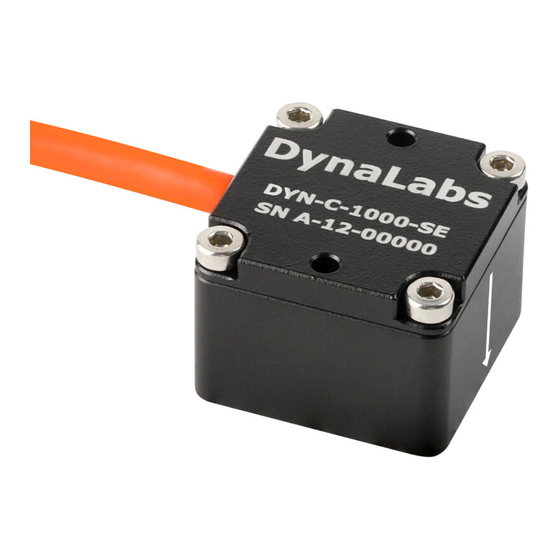
- Page 1 Model DYN-C-1000-SE 2g/4g/8g/10g/20g/40g/50g/100g/200g/500g Product Manual...
- Page 2 All rights reserved. Reproduction or issue to third parties in any form whatsoever is not permitted without written authority from the proprietors. Product Support If at any time you have questions or problems with the DYN-C-1000-SE sensors, please contact a Dynalabs engineer at: Phone: +90 312 266 33 34 (9 a.m.
- Page 3 All rights reserved. Reproduction or issue to third parties in any form whatsoever is not permitted without written authority from the proprietors. Table of Contents 1) Introduction ....................4 2) General Information ..................4 2.1) Unpacking and Inspection ................ 4 2.2) System Components .................
- Page 4 • Custom Connector • Base plate 2) General Information 2.1) Unpacking and Inspection Dynalabs products provide adequate protection for undamaged products to be transported. Document the damages that occur indirectly during the transport and contact the customer representative. 2.2) System Components...
- Page 5 All rights reserved. Reproduction or issue to third parties in any form whatsoever is not permitted without written authority from the proprietors. 2.3) Specifications Table 1: Specifications datasheet 1002SE 1004SE 1008SE 1010SE 1020SE 1040SE 1050SE 1100SE 1200SE 1500SE Full scale ±2 ±4 ±8...
- Page 6 Connector (Optional) D-Sub 9 or 15 pin, Lemo, Binder Mounting Adhesive or screw mount Base plate (Optional) Aluminum or Steel 9 g (aluminum) Weight (without cable) 19 g (steel) 2.4) Outline Drawing The dimensional properties of DYN-C-1000-SE sensors are given below;...
- Page 7 All rights reserved. Reproduction or issue to third parties in any form whatsoever is not permitted without written authority from the proprietors. 3) Operation and Installation 3.1) General The general sensor connector configuration is given below; Cable Code/Pin Configuration: • Red : V + Power supply voltage +6 to +20VDC.
- Page 8 • MIL-STD-810-H-2019 (Test Methods: 501.7 - High Temperature, 502.7 - Low Temperature, 514.8 - Vibration, 516.8 – Shock) DYNALABS MÜHENDİSLİK SANAYİ TİCARET LİMİTED ŞİRKETİ declares that above mentioned products meet all the requirements of the above mentioned standards and regulations.
Need help?
Do you have a question about the DYN-C-1000-SE and is the answer not in the manual?
Questions and answers