Table of Contents
Advertisement
Quick Links
MONITORING T2S - ETH
User Manual V1.4
THE NEW GENERATION OF MONITORING
Web-based User Interface
Extended Log Capabilities
Compatible with Catena
Copyright © 2013. Construction electroniques & telecommunications S.A.
All rights reserved. The contents in document are subject to change without notice.
The products presented are protected by several international patents and trademarks.
Address: CE+T S.a, Rue du Charbonnage 12, B 4020 Wandre, Belgium
www.cet-power.com - info@cet-power.com
Important Safety Instructions
Save these Instructions
www.cet-power.com
Advertisement
Table of Contents
Troubleshooting

Related Manuals for CE+T Power T2S-ETH


Summary of Contents for CE+T Power T2S-ETH
- Page 1 MONITORING T2S - ETH User Manual V1.4 THE NEW GENERATION OF MONITORING Web-based User Interface Extended Log Capabilities Compatible with Catena Important Safety Instructions Save these Instructions Copyright © 2013. Construction electroniques & telecommunications S.A. All rights reserved. The contents in document are subject to change without notice. The products presented are protected by several international patents and trademarks.
-
Page 2: Table Of Contents
3.3.2 Surge and transients ...................... 3.3.3 Other ..........................Maintenance ..........................Replacement and Dismantling ..................... 4. Product Code and Identification ......................Identification labels for T2S-ETH ....................5. Introduction ............................6. Hardware ............................... LEDs code during operations ....................... 6.1.1 LEDs code during normal operation ................ - Page 3 7.4.6 Events ..........................7.4.7 Log ..........................7.4.8 Connections ........................7.4.9 Files ..........................7.4.10 Parameters........................8. Catena ..............................Introduction ..........................User interface ..........................Ethernet connections ........................8.3.1 Rear connections......................8.3.2 Front connection ......................8.3.3 Troubleshooting ......................Configuration ..........................8.4.1 Network architecture ...................... Protocols .............................
- Page 4 12. Service ..............................13. Maintenance Task ..........................14. Annex 1: Supervisor alarms - T2S ETH ....................15. Annex 2: Module alarms - T2S ETH ....................... 16. Annex 3: Modbus ..........................16.1 Hardware Requirements ......................16.1.1 Cabling: .......................... 16.1.2 Baud rate, parity and mode .................... 16.2 Database Description .........................
- Page 5 Release Note: Release date Modified page Version Modifications (DD/MM/YYYY) number 11/04/2016 First release of the manual. 17, 32 and 39 Catena and SNMP details updated. 27/01/2017 Added Annex. 18/09/2017 42 - 47 Modbus Testing Procedure. 10/08/2018 Added SNMP Details. 03/10/2018 Updated Modbus details.
-
Page 6: Ce+T At A Glance
CE+T at a glance 1. CE+T at a glance CE+T Power designs, manufactures and markets a range of products for industrial operators with mission critical applications, who are not satisfied with existing AC backup systems performances, and related maintenance costs. -
Page 7: Abbreviations
Abbreviations 2. Abbreviations Twin Sine Innovation Enhanced Power Conversion Regular Digital Signal Processor Alternating current Direct current Electro Static Discharge Main Earth Terminal Manual By-pass TCP/IP Transmission Control Protocol/Internet Protocol Universal Serial Bus Protective Earth (also called Main Protective Conductor) Neutral Printed Circuit Board True Redundant Structure... -
Page 8: Warranty And Safety Conditions
Warranty and Safety Conditions 3. Warranty and Safety Conditions WARNING: The electronics in the power supply system are designed for an indoor, clean environment. When installed in a dusty and/or corrosive environment, outdoor or indoor, it is important to: • Install an appropriate filter on the enclosure door, or on the room’s air conditioning system. •... -
Page 9: Installation
Warranty and Safety Conditions 3.3 Installation • This product is intended to be installed only in restricted access areas as defined by UL60950 and in accordance with the National Electric Code, ANSI/NFPA 70, or equivalent agencies. • The Inverter System may contain output over current protection in the form of circuit breakers. In addition to these circuit breakers, the user must observe the recommended UL listed upstream and downstream circuit breaker requirements as defined in this manual. -
Page 10: Maintenance
Warranty and Safety Conditions 3.4 Maintenance • The modular inverter system/rack can reach hazardous leakage currents. Earthing must be carried out prior to energizing the system. Earthing shall be made according to local regulations. • Prior to any work conducted on a system/unit make sure that AC input voltage and DC input voltage are disconnected. -
Page 11: Product Code And Identification
Product Code and Identification 4. Product Code and Identification T2S-ETH product code with regards to sub rack: A) T2S-ETH Monitor Product Description Part Number TSI-T2S-ETH-NOVA - VEDA T312010010 TSI-T2S-ETH-BRAVO-MEDIA 24/48/60 Vdc T322010100 TSI-T2S-ETH-BRAVO-MEDIA 110/220 Vdc T322051000 B) Filler (Blank module to cover empty slots) -
Page 12: Introduction
Introduction 5. Introduction The T2S ETH stands for T2S Ethernet. It replaces the former T2S with the same form factor but with a front Ethernet connector replacing the former USB one. Like his predecessor, T2S ETH is a monitoring solution for the full TSI inverter range and is able to monitor up to 32 inverters through a friendly web base interface. -
Page 13: Hardware
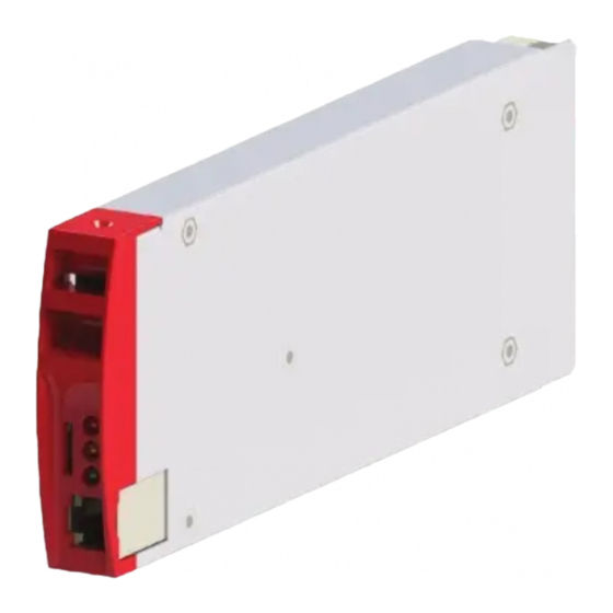
Hardware 6. Hardware T2S ETH provides 3 LEDs: Red for major alarm signaling, orange led for minor alarm signaling and green led for power and network connection status. The RJ45 is a standard ETH connector that could be connected on any IPv4 network. T2S ETH firmware can be upgrade using the Micro SD card. -
Page 14: Leds Code During Operations
Hardware 6.1 LEDs code during operations Flash low Flash fast Sequence one after the other Not used LED 6.1.1 LEDs code during normal operation LEDs code below corresponds to system in operation and T2S ETH fully operational. Green Orange Status Slave mode (when several T2S ETH on the same bus) Master Mode «... -
Page 15: Signaling Information
Hardware Green Orange Status Boot loader Web interface ON and in operation System file OK but no config file *.ini Error SD Card / File Error no configuration.ini 6.2 Signaling Information As it is designed to be used in the same shelf as former T2S, T2S ETH inherits the connections on the back. Note: The terminal connector accepts maximum wire size of 0.5 mm Important remarks: In a system with several shelves, T2S ETH is usually located in the first one (although it’s not mandatory) but relay... -
Page 16: Alarm Relay
Hardware 6.2.1 Alarm relay There are 3 alarm contacts: • Major • Minor • User selectable As one can see in the picture: contacts 5 and 6 are closed when no major alarm is present, contact 8 and 9 are closed when no minor alarm is present. Remark: Default mapping and level of each available alarm of the monitoring unit is available in “Annex 1: Supervisor alarms - T2S ETH”, page 69. - Page 17 Hardware Note: The colour of wires is irrelevant and may vary, but make sure the position of wires is exactly crimped. Pin Number Name Description CANH CANH pin for Candis CANL CANL pin for Candis GND_IAX Digital Communication Ground GND_IAX Digital Communication Ground 12V_IAX +12 V unregulated...
-
Page 18: Monitoring - Candis
Hardware 6.3 Monitoring - Candis T2S ETH also supports the Candis display and it is a monitoring device allowing the user to get information from inverter system. To enable candis, connect RJ45 CAT cable at rear side of the T2S ETH installed shelf and Candis. -
Page 19: Graphical User Interface - Catena
Hardware 6.4 Graphical User Interface - Catena The Catena display can be used with the T2S ETH. Catena is either available in rack mount or door mount version. 6.4.1 Description On front access, Catena has a wide 7’’ capacitive touch screen alongside 3 led following the same scheme as in T2S ETH and two connectors: USB type A and Ethernet (RJ45). -
Page 20: Wiring
Hardware 6.4.2 Wiring Catena configuration has to be selected in T2S ETH under monitoring, network, connection mode, hardware setup should be With Catena. This option has to be selected even before wiring. – Monitoring T2S - ETH User Manual – v1.4... -
Page 21: Graphical User Interface
Graphical User Interface 7. Graphical User Interface The user interface is the same if accessed with a laptop connected on front ETH connection, remotely on network, or through catena if one is present. The interface has a “top-down” philosophy: first screen gives a general overview, then one can go deeper and get more information on specific area by clicking the “magnifier icon”. -
Page 22: Login
Graphical User Interface 7.2 Login The user interface is accessible by typing the IP address of the system in a web browser. The default IP address is 192.168.0.2. Important remark: Web browser brand and version can change the interface proper behavior. It’s strongly recommended to use Google Chrome, Mozilla Firefox, OSX Safari. -
Page 23: Banner
Graphical User Interface 7.3.1 Banner 1 T2S Mode T2S ETH can be used redundant (2 in the same system), one being master, the second is slave. When used alone, T2S ETH is automatically Master. 2 Site name It’s a customizable field from configuration menu. User can set any string he wants. 3 ... -
Page 24: Toolbar
Graphical User Interface 3 System Clicking the magnifier will bring the user to information regarding the system such as redundancy, available power and so on. It is also the path to the module level monitoring. The three LEDs are showing the state of each converter. Example: if one converter of one module is in alarm, then the led will turn to orange. -
Page 25: Pages And Feature
Graphical User Interface Throughout the browsing, user can see following icons appearing: When accessing a page of depth two or more (such as module or log page), user can go back to previous page by clicking “back”. When browsing away from home page, user can go back straight to it by clicking the home page. Whenever a logged user click this button, he will be redirected to login page. -
Page 26: Ac Out
Graphical User Interface 7.4.3 AC Out This page displays the measurement made by the modules on the AC output Available values are: Measure Unit Voltage (V) Volts (V) Current (I) Ampere (A) Frequency(f) Hertz (Hz) Active Power(P) Kilo Watt (KW) Apparent Kilo Volt Ampere Power(S) -
Page 27: Module
Graphical User Interface 7.4.5 Module This page gives module by module measurement. T2S ETH is the monitoring solution for inverters which are all one phase modules. Many controls are available from this page to manage the module: User can set the module address he wants between 1 and 32 It’s not always easy to identify a module in front of a system. -
Page 28: Events
Graphical User Interface 7.4.6 Events Events page lists all events currently ongoing in the system. These are sorted by event occurrence time, latest event will be on top of the list. T2S ETH records maximum number of 2000 events as FIFO. -
Page 29: Connections
Graphical User Interface 7.4.8 Connections As described before, T2S ETH has 2 digital inputs and 3 alarm relays. State of each of these connections can be read through the “connections” page. An extra button “toggle” allows the user to test each relay manually, toggling it for a few seconds with the aim of detecting a mechanically failing device over the time. -
Page 30: Parameters
Graphical User Interface Language tab helps user so he can upload a language file and translate the whole interface in its own language. These files are available for certain languages in my.cet-power.com. If the required language is not available, get in touch with sales representative to request the interface translation. - Page 31 Graphical User Interface • Regional settings ƒ Language: user can select a language among those installed. See files menu ƒ Sitename: it’s a standard string which is displayed in the banner. ƒ Location: Location is the Place where the system is installed.
- Page 32 Graphical User Interface • Passwords Expert password: default is pass456 but it’s strongly recommended to change it. Software update do not change your password. In case of lost password, please refer to FAQ at page 65 • Network In Connection mode, Select Hardware setup as ƒ...
- Page 33 Graphical User Interface • Alarms MBP configured: should be configured and cabled to DigIn1 when a MBP is present. T2S ETH use this input to tell modules that MBP is engaged. Remote MBP: Should be configured when a CE+T external MBP unit is present and it is applicable only for the systems in US market.
- Page 34 Graphical User Interface • Relays Label ƒ Major Relay Name: dedicated to major relay – not possible to change ƒ Minor Relay Name: dedicated to minor relay – not possible to change ƒ Relay 3 name: It is a programmable relay and user can select a particular alarm.
- Page 35 Graphical User Interface • SNMP Traps ƒ Traps can be enabled for different events and alarms under this section. Trap receiver configuration has to be done under SNMP tab. ƒ Test Traps can also verified. 7.4.10.3 SNMP • SNMP SNMP configuration can be done from T2S ETH web page when logged in as expert login.T2S ETH when used as a standalone...
- Page 36 Graphical User Interface 7.4.10.5 Power • General Redundancy: number of redundant module can be set for each output phase. Source power ratio DC vs AC: percentage of power fed by DC. By default this parameter is set to 0, 100% on AC input. Booster 10x Iin: enable the boost (see manual of power module used for information on this feature).
- Page 37 Graphical User Interface • AC Out Phase shift & Vout for each phase: define phase shift between phase. Nominal Freq: nominal frequency 50 or 60 Hz. Nb of phases: Number of phase single or three phase. Short circuit voltage & hold time: short circuit hold time before shut down 10 to 600 seconds (default 60).
- Page 38 1 ƒ No power from AC IN phase 2 ƒ No power from AC IN phase 3 7.4.10.6 Info • T2S-ETH This tab provides information about the T2S ETH: ƒ Serial Number ƒ Software version ƒ Interface version ƒ Bootloader version ƒ...
-
Page 39: Catena
Catena 8. Catena 8.1 Introduction Catena is the display solution for T2S ETH. Using it, you get access on a 7’’ display directly in the system, providing the same graphical user interface as the T2S ETH when accessed remotely. 8.2 User interface As described before, the user interface is the same if the system is accessed remotely or directly on the 7’’... -
Page 40: Troubleshooting
Catena 8.3.3 Troubleshooting For any reason, if connection between Catena and T2S ETH cannot be established, the following popup will be displayed: Follow the steps listed here. If the problem persists even after a reset (or hard reset by power supply), try to connect directly on T2S ETH and check that it’s properly configured “With Catena”... -
Page 41: Protocols
Catena 8.5 Protocols Using Catena SNMP V2C, SNMP V3 and Modbus TCP support is enhanced to monitor the system. 8.5.1 SNMP v2c Implemented MIB file is CET-MIB. For configuration refer to section “SNMP”, page 46. 8.5.2 SNMP v3 Implemented MIB file is CET-MIB. Three different modes are available in SNMP v3 with subsequent parameters: •... - Page 42 Catena Address Description Unit Type 1016 Total available AC output apparent power 1030 Total AC input true power 1032 Total AC input apparent power 1034 Total DC input true power 1080 Worse AC output load status 1081 Worse AC output hardware status (inverters) 1082 Reserved 1083...
- Page 43 Catena Address Description Unit Type 2104 Phase 2 voltage V/10 S32/float 2106 Phase 2 current A/10 S32/float 2108 Phase 2 frequency Hz/100 S32/float 2110 Reserved 2112 Phase 2 worse power factor S32/float 2114 Phase 2 worse temperature °C/10 S32/float 2116 Phase 2 load ratio (W) S32/float 2118...
- Page 44 Catena Address Description Unit Type Reserved Phase voltage V/10 Reserved Phase current A/10 Reserved Phase frequency Hz/100 Input Group 2 Phase 1 Reserved Phase true power Reserved Phase apparent power Reserved Phase voltage V/10 Reserved Phase current A/10 Reserved Phase frequency Hz/100 Input Group 2 Phase 2 Reserved...
- Page 45 Catena Name Description Value Orange Recoverable Error 4 (bit 00000100) Non Recoverable Error 64 (bit 01000000) – Monitoring T2S - ETH User Manual – v1.4...
-
Page 46: Snmp
SNMP 9. SNMP 9.1 SNMP Configuration 9.1.1 Introduction This document describes the Management Information Base (MIB) schema design for standalone T2S ETH for SNMP v1 configuration and T2S ETH with Catena for SNMP V2C and V3 configuration. A MIB schema describes the structure of information served by a Simple Network Management Protocol Subsystem (SNMP) agent. -
Page 47: Snmp V1 Configuration
SNMP 9.1.3.2 MIB Design in the T2S ETH and Catena Products Each component in the system or device shall be monitored and therefore will be described by its own Management Information Base (MIB) structure file which describes the data provided by that MIB. The data elements in a MIB are grouped in objects, and each object may hold any number of child objects specified as either scalar values or tabular values. - Page 48 SNMP 10. To find the IP address of T2S ETH card IP Scanner tools can be used. 11. Refer section 9.2, page 57 for more information. 12. If you have not DHCP Disable DHCP. 13. Configure Network 14. If your Trap receiver is a server with host name then configure DNS if you want your trap to be received. 9.1.4.3 SNMP V1 agent configuration 1.
-
Page 49: Snmp V2C Configuration
SNMP 9. SNMP Base OID need not be modified 10. SNMP Agent Community is configurable, the same agent community name has to be used in NMS SNMP V1 profile. 11. Community name accepts a maximum of 15 ASCII characters. 9.1.4.4 SNMP V1 trap settings 1. - Page 50 SNMP 4. Click on “Network” sub menu 5. Connection mode Hardware setup should be with CATENA. 6. Ensure this option is selected before connecting T2S ETH to CATENA. 9.1.5.2 SNMP V2C agent configuration 1. SNMP V2C can be configured when T2S ETH is connected to Catena 2.
-
Page 51: Snmp V3 Configuration
SNMP 9.1.5.3 SNMP V2C trap settings 1. Port Trap Choose the port on which the trap is send and default port is port 162 2. Traps will not be received if the port number is changed. 3. Choose SNMP versions as SNMP V2C 4. - Page 52 SNMP 7. SNMP Port number is standard port 161 for V3 communication 8. SNMP V3 will not communicate when port number is changed from default port number even if the same port number is configured at the NMS end. 9. SNMP Base OID need not be modified 10.
- Page 53 SNMP 9.1.6.3 SNMP V3 Configuration Auth + No Encrypt. 1. SNMP V3 can be configured when T2S ETH is connected to Catena 2. Login to T2S web page in Expert login 3. Click on button “Parameters” at the end of the page 4.
- Page 54 SNMP 9.1.6.4 SNMP V3 Auth + No Encrypt trap settings 1. Port Trap Choose the port on which the trap is send and default port is port 162 2. Traps will not be received if the port number is changed. 3.
- Page 55 SNMP 7. SNMP Port number is standard port 161 for V3 communication 8. SNMP V3 will not communicate when port number is changed from default port number even if the same port number is configured at the NMS end. 9. Context name has to match the name used in NMS, Context name accepts a maximum of 15 ASCII characters. 10.
- Page 56 SNMP 5. Trap user name is configurable has to match the name created in Trap receiver, User name accepts a maximum of 15 ASCII characters. 6. Trap password is configurable has to match with the password created in Trap receiver, Password accepts a maximum of 15 ASCII characters.
-
Page 57: Advanced Ip Scanner
SNMP 9.2 Advanced IP Scanner This section helps you indentify your T2S ETH IP when DHCP is enabled. Advanced IP Scanner open source software available online, this application need not be installed in local machine. It is a reliable and free network scanner to analyze LAN. -
Page 58: Snmp V1 Testing
SNMP 9.3 SNMP V1 Testing This section helps you to test the SNMP of your T2S ETH unit. Lots of software (free or not) is available online. Current example is given using “ iReasoning MIB Browser ”. Here are the steps to follow: 1. - Page 59 SNMP 4. Click “ advanced ” if you changed settings like Read Community. 5. Select the operation, for example “WALK” and click “Go”. 6. The result looks like – Monitoring T2S - ETH User Manual – v1.4...
-
Page 60: Snmp V1 Traps
SNMP 9.4 SNMP V1 Traps To check the SNMP V1 traps, 1. Click Tools > Trap Receiver on the menu bar. 2. You should have defined the IP address of the laptop running MIB Browser in the T2S ETH configuration in order to retrieve trap. - Page 61 SNMP 5. Press Ctrl + S to save the file with the same file name 6. Navigate to Modules Tab 7. Check CET-TSI-MIB and CET-TSI-SIM are listed under available MIB Modules 8. Select the above files and Press right arrow to move the files to Loaded MIB Module 9.
-
Page 62: Steps To Discover Device
SNMP 9.5.2 Steps to Discover Device 1. Navigate to Discovery tab 2. Select IP option and enter From and To IP addresses, this would be the IP address range of T2S ETH IP 3. SNMP Agent profile to be selected based on the type of SNMP communication 4. -
Page 63: Steps To Get / Walk Oid
SNMP 9.5.3 Steps to Get / Walk OID 1. Select the SNMP Agent under remote SNMP agent 2. The Added SNMP Agent has to be listed in the list 3. Right click on the OID to perform walk or Get 9.5.4 Steps to Add SNMP V3 User 1. - Page 64 SNMP – Monitoring T2S - ETH User Manual – v1.4...
-
Page 65: Faq
4. How can I reset my admin password if I have unfortunately forgotten it? In case of password lost, a new temporary password (valid 24 hrs after creation) can be issued by CE+T Power. To receive a temporary password, send an email with your T2S ETH serial Number and the date at which you expect to go back on site to change the password to customer.support@cet-power.com... -
Page 66: Trouble Shooting And Defective Situations Fixing
Repair registering guidelines may be requested by email at repair@cet-power.com. • The RMA number should be mentioned on all shipping documents related to the repair. • Be aware that products shipped back to CE+T Power without being registered first will not be treated with high priority! •... -
Page 67: Service
Service 12. Service For Service • Check Service Level Agreement (SLA) of your vendor. Most of the time they provide assistance on call with integrated service. If such SLA is in place, you must call their assistance first. • If your vendor doesn’t provide such assistance (*) you may call CE+T directly. Toll free Number 1(855) 669 - 4627(**) Service is available from 8:00 A.M. -
Page 68: Maintenance Task
Maintenance Task 13. Maintenance Task As maintenance will perform on live system, all task should perform only by trained people with sufficient acknowledge on TSI product. Tasks: • Identify the site, customer, responsible, cabinet number, product type. • Download and save configuration file for back up. •... -
Page 69: Annex 1: Supervisor Alarms - T2S Eth
Annex 1: Supervisor alarms - T2S ETH 14. Annex 1: Supervisor alarms - T2S ETH This is the list of alarms issued by supervisor. Other alarms are issued by other modules (see section 15, page 72). The supervisor is able to generate alarms that are related to the system, to inverter modules, or to itself. Alarms related to inverters will be seen as system alarms when module alarm is present on all inverters. - Page 70 Annex 1: Supervisor alarms - T2S ETH System Alarms Text ID Name Level Def. Map Description All modules outputs are derated because of an over Temperature Derating event temperature. All modules outputs are turned off because of an Overtemperature event over temperature.
- Page 71 Annex 1: Supervisor alarms - T2S ETH Supervisor Module Alarms Text ID Name Level Def. Map Description Log Nearly Full mappable disabled Log file is nearly full. Log Full mappable disabled Log file is full (with information loss). Log Cleared event Log file has just been cleared.
-
Page 72: Annex 2: Module Alarms - T2S Eth
Annex 2: Module alarms - T2S ETH 15. Annex 2: Module alarms - T2S ETH Module not Recoverable Alarms Text ID Name Level Def. Map Check and Action Fan Failure Minor Fan replacement Permanent Fault (2) Minor Permanent Fault (3) Minor Permanent Fault (4) Minor... - Page 73 Annex 2: Module alarms - T2S ETH Module Recoverable Alarms Text ID Name Level Def. Map Check and Action Parameter Query Minor Inverter is updating his parameters Parameter Mismatch Minor Parameters incompatible with configuration file Parameter Not Ready Minor Check AC, configuration and allocated phases Recoverable Fault Minor (42)
- Page 74 Annex 2: Module alarms - T2S ETH Module Alarms Text ID Name Level Def. Map Check and Action temperature measured from the heat sink - 88C for Temperature Derating Minor bravo and 70C for media Output Overload (P) Minor Check load condition Recoverable Minor Fault (79)
- Page 75 Annex 2: Module alarms - T2S ETH Module AC Input Alarms Text ID Name Level Def. Map Check and Action THD Too High Minor Check AC IN configuration and live value Output Minor Check AC IN configuration and live value Synchronization Error (174) Minor...
- Page 76 Annex 2: Module alarms - T2S ETH Module DC Input Alarms Text ID Name Level Def. Map Check and Action Source V Too Low Minor Check VDC parameter and live value Stop Source V Too High Minor Check VDC parameter and live value Stop Error (217) Minor...
-
Page 77: Annex 3: Modbus
Annex 3: Modbus 16. Annex 3: Modbus 16.1 Hardware Requirements 16.1.1 Cabling: ModBus RTU is available on the on RJ45 connector located on the back plane of the rack containing the T2S ETH controller. The pin out of this connector is the following: Pin Number Name Description... -
Page 78: Database Description
Annex 3: Modbus 16.2 Database Description 16.2.1 Typographic convention: In this document the following naming convention will be used to represent the type of a variable: The first letter will indicate if the variable is signed (S) or unsigned (U). Then the following digit(s) will indicate the number of bits needed to store the variable. - Page 79 Annex 3: Modbus 16.2.3.1 INPUT REGISTERS ELEMENTS (Read-Only 16-bit wide) Module table (0x0000) The table described below represents the information that can be retrieved regarding a particular module. Maximum amount of module is set to 32. Each of them is identified by an address ranging from 1 to 32. BASE ADDRESS: 0(0x0000) + 31*(Module address –...
- Page 80 Annex 3: Modbus Index Name Description Type bNoEPC Flag (true or false) that indicates if module has an AC input (EPC) or not wPoutNominalW Nominal output power (W) wPoutNominalVA Nominal output power (VA) wVinNominalAC Nominal AC input voltage (0.1V) wVinNominalDC Nominal DC input voltage (0.1V) wVinNominalFreqAC Nominal AC frequency (0.1Hz)
- Page 81 Annex 3: Modbus Index Name Description Type Number of modules not seen by T2S ETH in the phase (accordingly to bNbInvNT bNbOndCfg) AC group table (0x0730) The table described below represents the information that can be retrieved regarding a particular AC group. Maximum amount of AC group is set to 4.
- Page 82 Annex 3: Modbus Miscellaneous information table (0x07BC) The table described below represents the miscellaneous information that can be retrieved regarding T2S ETH and system. BASE ADDRESS: 1980(0x07BC) Index Name Description Type bOldVersionNumber Deprecated. Always 0x00 ePhaseNumber Number of phase configured in the system lSerialNumber T2S ETH serial number wTempoMajorAl...
- Page 83 Annex 3: Modbus Index Name Description Type bDaylightSaving Flag (true or false) that specify if daylight saving is enable or not wYear Year number Alarm table (0x07DA) The table described below represents the information that can be retrieved regarding alarms. Maximum amount of entries is set to 50.
-
Page 84: Status And Constants Description
Annex 3: Modbus 16.3 Status and Constants Description 16.3.1 Module status explanation (A1): 16.3.1.1 eStatusACOut: Name Description Value Standby running. This means that the module is delivering output Standby. This mean that the module is manually OFF Standby with error. This means that the module is not SBWE delivering output due to an unrecoverable error Standby with recoverable error. -
Page 85: Alarm Sources
Annex 3: Modbus 16.3.3 Alarm sources: Name Description Value T2S ETH Device responsible of the alarm is the T2S ETH controller. Device responsible of the alarm is the module number XX MOD XX 1-32 where XX is the value Source of the alarm is the whole system (e.g. if all module SYSTEM are sharing the same alarm). -
Page 86: Examples
Annex 3: Modbus 16.4 Examples 16.4.1 Introduction In all the following examples, assumption will be made that T2S ETH controller Modbus RTU slave address is 1 (0x01). 16.4.1.1 Reading simple variables: Ex 1: Reading output voltage of module #5 Field Value Description Function... - Page 87 Annex 3: Modbus Reading an invalid entry Let’s assume that there are only 2 alarms present in the system. Then reading alarm entry #3 should return an invalid entry Field Value Description Function 4 (0x04) Read input register Address 2014 (0x07DE) 2010 + 2*(3-1) = 2014 (see alarm table, page 83) Number of registers 2 (0x02)
- Page 88 Annex 3: Modbus 16.4.1.3 Reading configuration: Reading entry #1 Field Value Description Function 4 (0x04) Read input register Address 4160 (0x1040) 4160 + 20*(1-1) = 4160 Number of registers 20 (0x14) Alarm entry is 20 registers wide Master frame: 0x01 0x04 0x10 0x40 0x00 0x14 0xF5 0x11 T2S ETH frame: 0x01 0x04 0x28 0x01 0xB8 0x00 0x00 0x01 0x04 0x01 0x01 0x44 0x43 0x20 0x31 0x20 0x3A 0x20 0x56 0x64...
- Page 89 Annex 3: Modbus Exceptions: Textual parameter As one can see, the configured value field is 16 bit wide. Consequently, only integer values can be read (or further configured) using this way. There are 3 parameters that are not integer values but strings. Thus, the values returned in the “Configured value”...
-
Page 90: Modbus Testing
Annex 3: Modbus 16.5 Modbus Testing In order to test the Modbus communication functionalities, please install the program “Radzio ! Master Modbus Simulator” on your computer. • Website: http://en.radzio.dxp.pl/modbus-master-simulator/ • Direct download: http://en.radzio.dxp.pl/modbus-master-simulator/RMMS.zip 16.5.1 Requirement: • USB to RS485 interface cable (For example USB-RS485-WE cable, FTDI chip), Fig 1 Fig 1: FTDI cable •... -
Page 91: Modbus Testing Procedure
Annex 3: Modbus 16.5.2 Modbus Testing procedure Perform the following steps to test the Modbus 1. Connect FTDI cable on the RJ45 port at the back plane of the T2S-ETH with ○ Yellow on pin 8. ○ Orange on pin 6. - Page 92 Annex 3: Modbus 5. Click on the Connection settings icon in the tool bar. Fig 5: Connection settings icon 6. Select Modbus RTU in the Connections settings window Fig 6: Connection settings window – Monitoring T2S - ETH User Manual – v1.4...
- Page 93 Annex 3: Modbus 7. Verify the Modbus RTU parameters are matching with the T2S-ETH in the Modbus section (Fig 7). Fig 7: Modbus settings in T2S ETH 8. Close the Connection settings window in Radzio!. 9. Click on the Connect icon in the Radzio tool bar in order to establish the connections. (Fig 8) Fig 8: Connect icon –...
- Page 94 Annex 3: Modbus 10. Click New Modbus sheet icon, to open the new Modbus sheet. (Fig 9) Fig 9: New Modbus sheet icon 11. Modify the Device Settings in the new modbus sheet. (Fig 10) ○ Set the Device ID (Default value is 1) ○...
- Page 95 Annex 3: Modbus 12. Access the desired addresses at the Modbus sheet in Radzio (Fig 11) as described in the Modbus document (Fig 12). If you only see zeros or bad values, check the Frame counter (Fig 11) to be sure that you receive “Valid responses”.
Need help?
Do you have a question about the T2S-ETH and is the answer not in the manual?
Questions and answers