
Related Manuals for Nilfisk cfm S2


Summary of Contents for Nilfisk cfm S2
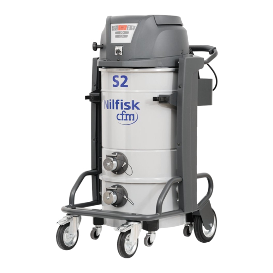
- Page 1 S2 - S3 service manual Nilfisk-CFM Via Porrettana 1991 - 41059 Zocca (Modena) Italy - Tel. +39 059 9730000 - Fax +39 059 9730099 - www.nilfisk-cfm.com - info@nilfisk-cfm.com S.p.A.
-
Page 2: Table Of Contents
F Spare parts page 68 .................................... F.1 - Spare parts page 69 ........................G Instruments page 70 ..................................G.1 - Special instruments page 71 ....................H Wiring page 72 ....................................H.1 - Wiring diagram ..................page 73 S2 - S3 service manual... -
Page 3: Preface
The Technical Service Bulletins represent a supplement of the spare parts list until the next is published. The manuals and bulletins must always be available during repairs. Other technical documents on the S2-S3 series may be re- quired for repairs. -
Page 4: Symbols
This symbol is used to indicate the safety instructions which must be observed to prevent damaging the vacuum cleaner and malfunctions. This symbol indicates suggestions and instructions to simplify jobs and guarantee safe working conditions. S2 - S3 service manual... -
Page 5: A Safety Instructions
Safety instructions... -
Page 6: Operator Safety
, depending on the occupied vol- ume, including carcinogenic and pathogenic dusts such as asbestos. Class H14 Hepa filter in accordance with standard EN 1822; retains at least 99.995% of vacuumed particles (See EN60335-2-69, Enclosure A.A). S2 - S3 service manual... - Page 7 Do not use without the complete filter system in place. Class H vacuum cleaners are identified by a label with the following text. S2 - S3 service manual...
- Page 8 In the case of electrical vacuum cleaners/instruments connected to the vacuum cleaner, always refer to the user manual and safety instructions. WARNING - DANGER ! Take care not to raise dust during maintenance operations. Wear a P3 protective mask. S2 - S3 service manual...
-
Page 9: B Technical Data
Technical specifications... -
Page 10: Technical Data
• Storage conditions: T : -10 +40 °C - Humidity: ≤ 85% • Operating conditions: Maximum altitude 800 m (up to 2,000 m with reduced performances) T : -10 +40 °C - Humidity: ≤ 85% S2 - S3 service manual... -
Page 11: C Components
Components... -
Page 12: Trolley
C.1 - Trolley Trolley Upright Accessory support C.2 - Handle complete with cable carrier S2 - S3 service manual... -
Page 13: Filtering Chamber With Complete Inlet And Deflector
C.3 - Filtering chamber with complete inlet and deflector Filtering chamber Complete inlet Deflector S2 - S3 service manual... -
Page 14: Complete Container
C.4 - Complete container 100 L container 50 L container 40 L container S2 - S3 service manual... -
Page 15: Accessories Rack
C.5 - Accessories rack C.6 - Filter ring and seal Filter ring Filter ring seal S2 - S3 service manual... -
Page 16: Filter With Filter Catch Clamp
C.7 - Filter with filter catch clamp Filter Filter catch clamp C.8 - Filter shaker cage S2 - S3 service manual... -
Page 17: Complete Motor Head
C.9 - Complete motor head with cable and plug Motor head Cable and plug C.10 - Motor head closing band S2 - S3 service manual... -
Page 18: Control Panel
C.11 - Control panel C.12 - Filter shaker system S2 - S3 service manual... -
Page 19: D Vacuum Cleaner Operation
Vacuum cleaner operation... -
Page 20: Controls And Indicators
Third motor Start/Stop indicator and button start/stop the third motor with this button. When this button is pressed all the motors stop simultaneously. The motors and internal Stop button components of the vacuum cleaner will still be electrically powered. S2 - S3 service manual... - Page 21 Wait to let the dust to settle before restarting the vacuum cleaner. If the indicator is still red even after the filter has been shaken, change the filter. S2 - S3 service manual...
- Page 22 Release the container with the lever, then remove it and empty it. Replace the container after having checked the condition of the seal. Stop the vacuum cleaner before performing this operation. Let the dust settle before removing the container. S2 - S3 service manual...
-
Page 23: E Troubleshooting
Troubleshooting... -
Page 24: Electrostatic Discharge
• Transport electronic components in conductive packaging (special packs to discharge electrostatic charges for example). Before proceeding with these operations, turn off the vacuum cleaner and remove the plug from the power socket. S2 - S3 service manual... -
Page 25: Trolley
Unscrew the 4 screws fixing the upright side panel by hand or with a screwer. The screws in the front are a different length. The longer screws must be used near the reinforcing spacer in the side-panel. Do not swap screws S2 - S3 service manual... - Page 26 E.2 - Trolley Remove the side-panel. View of the upright. Use a hex-head wrench to loosen the top screw holding the side bracket. Loosen the bottom screw too. S2 - S3 service manual...
- Page 27 Take care when removing the 4 screws. Hold the filter chamber firmly Proceed by unscrewing the handle with the cable carrier. Use a hex-head wrench to tighten the 2 screws on each side of the handle. S2 - S3 service manual...
- Page 28 Take care when removing the 4 screws. Always hold the handle firmly. To remove and change the cable carrier, unscrew the 6 screws holding it on the handle. Make sure the cable carrier is facing upwards. S2 - S3 service manual...
- Page 29 To remove and change the accessories support, unscrew the 2 screws holding it on the upright with a hex-head wrench. Fit the accessories supports facing the right way. This is important also in order to connect the grip properly. S2 - S3 service manual...
- Page 30 To remove and replace the fixed wheels, unscrew the nylock nuts with a wench. Make sure the bolts are tight after changing the wheels. The wheel should turn freely. S2 - S3 service manual...
- Page 31 E.2 - Trolley To remove and replace the accessories rack, unscrew the bolts under the front of the trolley. Use a suitable hex-head wrench. Remove the protective plug to remove the castors. S2 - S3 service manual...
- Page 32 Make sure the bolts are tight after changing the wheels. Block the trolley in place with the brakes to make changing the wheels easier. The brake should only be activated and deactivated with the feet. Never use your hands. S2 - S3 service manual...
-
Page 33: Filtering Chamber With Complete Inlet And Deflector
The deflector must be turned to the correct position (towards the container below). Do not fit the deflector facing upwards. Make sure the tongue that guarantees earth continuity between the motor head the filtering chamber is always fitted. S2 - S3 service manual... - Page 34 The complete inlet must be installed correctly (with the seal between the inlet and the filtering chamber and the screws tightened properly). If the screws aren’t tightened properly, this could cause air leaks (vacuum loss). S2 - S3 service manual...
-
Page 35: Container
Unscrew the bolt in the wheel bracket using a hex-head wrench. To remove the release lever, use an Allen wrench to unscrew the hex-head screws in the bush welded on the container. S2 - S3 service manual... - Page 36 Remove the whole lever, opening it out so it comes off the 2 welded pins. To remove and replace the roller pin, use a screwdriver and a hex-head wrench. Make sure the roller pin slides freely. S2 - S3 service manual...
- Page 37 Check the container couples correctly and presses against the seal properly. Keep your hands in the right place when coupling the container. S2 - S3 service manual...
-
Page 38: Filter
(PPE) suitable for the hazardous nature of the dust collected. Refer to the laws in force. The filter must be changed if it is blocked, torn or cannot guarantee high filtering efficiency. If shaking the filter isn’t enough, it must be replaced. S2 - S3 service manual... - Page 39 Before positioning the motor head on the filter, arrange the filter properly in the filter chamber. Position the filter with the bags completely extended to guarantee optimal filtering. S2 - S3 service manual...
- Page 40 If the movement isn’t right, lift the motor head and align the filter. Try shaking again. When shaking, hold the knob correctly and take care not to trap your fingers. S2 - S3 service manual...
- Page 41 Before closing the band again, centre the motor head properly on the filtering chamber. The motor head flange must be centred and positioned perfectly on the seal of the filter ring. S2 - S3 service manual...
-
Page 42: Complete Motor Head
In this case, take great care not to trap your fingers. Proceed by unscrewing the filter shaker knob. Unscrew the 4 screws positioned every 90° around the motor head. S2 - S3 service manual... - Page 43 All the screws are the same length, except the one under the main switch which is much longer. Now the motor cover can be removed from the base. Take particular care with the main switch. Pull it out, removing also the control panel. S2 - S3 service manual...
- Page 44 Pull the motor cover off, taking care not to damage the control panel. Turn the motor cover over and unscrew the screws inside. Remove the motor cover from the top cover. S2 - S3 service manual...
-
Page 45: Spare Parts
In any case we recommend using original spare parts, which include pre-bonded sponges. Remove the round sponge in the filter shaker lever. S2 - S3 service manual... - Page 46 90°. Pull the press-fit pipes off the connectors. During assembly make sure they fit properly in the connectors and that the yellow and blue colour codes are respected. Pull the pipes off the internal clips. S2 - S3 service manual...
- Page 47 Pull also the Faston terminal of the blue cable off connector N on the terminal board. When wiring, make sure the cables are laid out properly and hold them in place with appropriate ties. S2 - S3 service manual...
- Page 48 The bridge between L and N is wired in only on heads with 3 motors. To remove the board, unscrew the hex-head screw at the bottom. Unscrew the screws at the sides of the board. S2 - S3 service manual...
- Page 49 Remove the board, pulling it upwards. Unscrew the screws and remove the power cable of the main switch. When wiring, make sure the Faston terminals are firmly fixed on the connectors and the terminals are tight on the terminal board. S2 - S3 service manual...
- Page 50 Pull off the green connector and connect the blue and brown wires to the board. Pull off also the Faston terminals on the side of connectors M1-M2-M3. S2 - S3 service manual...
- Page 51 Always make sure the Faston terminals have been crimped correctly. Remove the ties holding the cables on the motor mounting plate to make wiring easier. Before removing the board completely from the motor head, check all the connectors have been disconnected. S2 - S3 service manual...
- Page 52 Each corner of the motor stator pack has an output cable. 2 blue cables connected to the brushes of the same motor, 2 connected respectively to connector M1-M2-M3 of the board and 1 to the terminal board. S2 - S3 service manual...
- Page 53 M6 screws on the motor mounting plate using a hex-head wrench . Hold the plate firmly on both sides and lift. The plates lifts away with the 3 motors mounted on it. S2 - S3 service manual...
- Page 54 To remove the terminal board, screw in the 2 screws holding it on the plate. Pull the motor through the hole in the plate. Take care not to damage the cables. Turn or tilt the motor to pull it out. S2 - S3 service manual...
- Page 55 Remove the 4 baseplates with the butterfly vacuum cutoff valves inside from their housing in the motor mount of the head. The 3 spacers of the butterfly vacuum cutoff valves must face upwards as shown in the photo. S2 - S3 service manual...
- Page 56 Proceed by unscrewing the M8 screws on the motor mount to remove the 2 spacers and the filter shaker. On heads with 2 motors (S2) remove also the baseplate closing the hole of the 3rd motor. S2 - S3 service manual...
- Page 57 Turn the head over again and loosen the central bolt holding the filter shaker shaft. Hold the shaft while you unscrew the bolt. When fixing the shaft with the central screw, always insert the serrated washer to prevent it slipping when shaking. S2 - S3 service manual...
- Page 58 Remove the base of the motor cover from the motor mount. Turn the motor mount and pull the filer shaker shaft out of the central bush. S2 - S3 service manual...
- Page 59 D.6x1/8” fitting, blue on the external D.6x M5 fitting. The pipes are press-fit in the fittings. Use Locktite on the nuts of the air fittings. Unscrew the 3 screws holding the central bush on the motor mount. S2 - S3 service manual...
- Page 60 E.6 - Complete motor head Remove the bush and seal. To dismantle the filter shaker system, unscrew the 4 screws holding it on the plate. Remove the filter shaker. S2 - S3 service manual...
- Page 61 To remove the 2 bumpers, unscrew the 2 bolts holding them on the frame with a hex-head wrench. Remove the bumpers and washer. To remove the filter shaker shaft, pull it out from one side of the bush. S2 - S3 service manual...
- Page 62 Then remove the shaft also from the other bush. The 2 bushes must be press-fit and inserted from the outside in the holes on the box. Make sure the bushes are a correct fit by sliding the filter shaker shaft. S2 - S3 service manual...
- Page 63 Make sure Faston terminal 6.3 is connected to the board, and Faston terminal 4.8 is connected to the terminal board. If the vacuum motors are noisy or produce a lot of sparks, the brushes may need changing. S2 - S3 service manual...
- Page 64 E.6 - Complete motor head To change the brushes, bend and release the tab holding the motor cap. Do the same with the tab on the other side. Open the tongues holding the brushes. Pull off the motor cap. S2 - S3 service manual...
- Page 65 Pull off carefully, taking care not to damage the tongue of the brushes. Press down on the tongue blocking the motor brush with a flat blade screwdriver. Pull out the brush. S2 - S3 service manual...
- Page 66 H07 RN-F. The same rule applies if an extension is used. All the sockets, plugs and commutators must have the same IP protection degree as the vacuum cleaner, as indicated on the data plate. S2 - S3 service manual...
- Page 67 If there are electrostatic currents on the vacuum cleaner, the earth is probably not connected or in a poor condition. In this case check the earth connections, in particular those of the inlet fittings; the hose must be antistatic. S2 - S3 service manual...
-
Page 68: F Spare Parts
Spare parts... - Page 69 F.1 - Spare parts Use the current spare part list. S2 - S3 service manual...
-
Page 70: G Instruments
Tools... - Page 71 Used to check the amperage (Amps) and voltage (Volts). Vacuum meter Used to measure the vacuum power with the inlet closed (mbar). Airflow meter Used to measure the airflow with the inlet open (m /h). S2 - S3 service manual...
-
Page 72: H Wiring
Wiring... -
Page 73: Wiring Diagram
Motor switch 1 Motor switch 2 Motor switch 3 Filter shaker motor Level control Compressed air pressure switch Alarm - air speed in the suction tube is less than 20 m/s Antidisturb filter Main switch S2 - S3 service manual...
Need help?
Do you have a question about the S2 and is the answer not in the manual?
Questions and answers