Advertisement
Quick Links
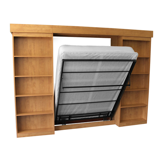
Library Bed
™
The
[Model #BC-2: Sliding Bookcase]
Cabinet Cut List & Assembly Instructions
Fits all Single/Twin, Double/Full, Queen Beds
Issue:032311
© 2010 Murphy WallBed Systems Inc.
2650 N. Lakeview #308
Chicago, IL 60614
Toll Free:
877-887-1717
Let's build a Wallbed together!
Phone:
773-248-5188
Fax:
773-281-6430
Advertisement

Related Manuals for MWBS Library Bed BC-2

Summary of Contents for MWBS Library Bed BC-2
- Page 1 Library Bed ™ [Model #BC-2: Sliding Bookcase] Cabinet Cut List & Assembly Instructions Fits all Single/Twin, Double/Full, Queen Beds Issue:032311 © 2010 Murphy WallBed Systems Inc. 2650 N. Lakeview #308 Chicago, IL 60614 Toll Free: 877-887-1717 Let’s build a Wallbed together! Phone: 773-248-5188 Fax:...
-
Page 2: Project Start-Up
Project Start-Up Familiarize yourself with all of the components in the Library Bed cartons and thoroughly study this manual so you may plan the steps required to complete this project. Study all illustrations and plan drawings. Make sure that the space available is adequate for the specified dimensions of the bed cabinet, both in the open and closed positions. - Page 3 BC-2 Sliding Bookcase Hardware Components List #10 x 3/4” Pan Head Square Screw 3” x 5/16” Bolt & T-Nut Washer #6 x 5/8” Flat Head Phillips Screw See pgs. 8,13,16 See pg. 8 (attach steel tube) See pg. 14 (attach AL Rail and Nylon Carriers) (attach Bottom Roller Guide} Scale is 1:1 Scale is 1:1...
- Page 4 STEP #1 BED CABINET COMPONENT CUT LIST SINGLE/TWIN BED Numbers in parenthesis ( ) are mm Cabinet Material: 3/4“ (18) MDF or Plycore QTY PART WIDTH LENGTH Right Side Panel 16” (406) 85” (2159) Left Side Panel 16” (406) 85” (2159) Front Kick 4 1/2”...
- Page 5 STEP #1 BED CABINET ASSEMBLY Assemble parts 1-7. Note that the Top Panel (6) is assembled between Left and Right Side Panels (1,2). The Library Top (7) is fastened to the top of the whole assembly. NOTE: Do not assemble parts 8, 9 or 10 at this time. Assembly of parts 1-7 are shown below.
- Page 6 STEP #2 BED CABINET POSITIONING Position Bed Cabinet to wall - Loosely attach to studs with #8 x 3” wood screws. Be sure to locate at least three wall studs for secure attachment.
- Page 7 STEP #3 SIDE CABINET COMPONENT CUT LIST; LEFT AND RIGHT SINGLE/TWIN BED Numbers in parenthesis ( ) are mm #(L) #(R) PART WIDTH LENGTH Right Side Panel 16” (406) 85” (2159) Left Side Panel 16” (406) 85” (2159) Front Kick 3 13/16”...
- Page 8 STEP #3 SIDE CABINET ASSEMBLY Assemble parts 11, 12, 13, 14, 15, 17, 18, 19 and 21 as shown below. NOTE: Parts 16 are adjustable shelves and will be added later. Part 18 mounts between 11 and 12. Part 20 will be added to assembly later. 2.0”...
- Page 9 STEP #4 SIDE CABINET POSITIONING Position and secure Left and Right Side Cabinets to Bed Cabinet using #8 x 11/4” wood screws. Square and level bed cabinet and left and right side cabinets. Make final secure attachment through the back of Top Facia (5) of the Bed Cabinet using (3) #8x3” wood screws, into studs.
- Page 10 STEP #5 INSTALL STEEL SUPPORT Fasten the square 1.5”x1.5” (38 x 38) Steel Support (10) to the top of the assembly using the provided 3.0” bolts and T-nuts. The Steel Support should be centered on top of the bed cabinet and bolt holes should be 14.0” (356) from the wall. Use the holes in the support to guide for drilling.
- Page 11 STEP #6 INSTALL LEFT END RUBBER SAFETY STOP Slide one rubber safety stop to end of left track in position shown below. Loosely tighten to track with provided screws, you will tighten later.
- Page 12 STEP #7 SLIDING BOOK CASE COMPONENTS NOTE: Two of each part are included for the identical left and right sliding cabinet assemblies. SINGLE - SLIDING BOOK CASE Numbers in parenthesis ( ) are mm PART WIDTH LENGTH Right Side Panel 8”...
- Page 13 STEP #7 SLIDING BOOKCASE VISUAL PART REFERENCE & ASSEMBLY Assemble Left and Right Sliding Cabinets as shown below. Attach backs with 1 3/4” Wood Screws, from the back side, into 25, 26 and 29 (3 in each shelf). Fasten 2”x2” Angle Brackets over top back corner of 29 and 30 as shown below using 8x3/4”...
- Page 14 STEP #7 INSTALL NYLON CARRIERS Drill 3/8” (10mm) holes in the tops of the Sliding Book Cases as shown below. Screw Nylon Carriers through the top, into the threaded plates. Do not tighten nuts at this point. 3.5” (89) Nylon Carrier .375”...
- Page 15 STEP #7 INSTALL SLIDING ROLLERS Install (2) Sliding Rollers to the back bottom side of each Sliding Cabinet approximately 3.5” (89) up from the bottom of Sliding Cabinet (opposite of the Deck, #14) to the center of the rollers. More important, be sure that rollers will line up on the Front Toe pieces of the Left Side, Right Side and Bed Cabinets (If they are too high they will not function properly).
- Page 16 STEP #8 MOUNT SLIDING BOOK CASES Hang one Sliding Book Case on Left Track. Next, slide on two Rubber Safety Stoppers back to back but do not secure. Hang the second Sliding Book Case and the last Rubber Safety Stop. Both Book Cases and all 4 Safety Stops should be on the left Aluminum Track at this point.
- Page 17 Using the adjuster bolts on the 4-wheel Nylon Carriers, level and square the Sliding Book Cases. Tighten the Rubber Safety Stops in their proper positions. Attach Front Valances (8,20), and Nailer (9). Install all adjustable shelves in cabinets and book cases. Install Murphy Bed Mechanism.
Need help?
Do you have a question about the Library Bed BC-2 and is the answer not in the manual?
Questions and answers