Advertisement
Quick Links
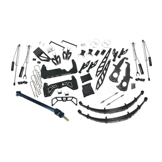
2011-2019 GM 2500 / 3500
10"-12" LIFT KIT
#52370 / 52371
(27" x 10" x 7")
#12. Lift Spindles (2)
#10. Lift Blocks (2)
#20. U-Bolts (4)
(45" x 14" x 14")
#19. Rear Crossmember (1)
#18. Front Crossmember (1)
#6. Skid Plate (1)
#21. Sway Bar End Links (2)
(not pictured)
#13. Compression Struts (2)
#3. Lower A-Frame Support Rods (2)
#5. Front Brake Lines (2)
#5. Rear Brake Lines (3)
BOX 1
5/8" x 14-1/4" x 3" (sq.)
BOX 2
Packaging Inspection Check-O Form
Name(s):_______________________________________
Date box was packaged, inspected, weighed & veri ed to
insure all parts were inside & correct:________________
(22" x 16" x 10")
#8. Torsion Bar Drop Brackets (2)
#15. Front (Front) Bump Stop
Brackets (2)
#16. Di Drop Brackets (2)
#9. Rear Bump Stop Brackets (2)
#11. Front (Rear) Bump Stop
Brackets (2)
#7. Front Bump Stop Retainer
Brackets (2)
#17. Compression Strut Brackets (2)
#4. Hardware Bags (2)
#14. CV Axle Spacers (2)
#2. Compression Strut Nut Mounts (2)
#23. Weld In Filler Plate (1)
(not pictured)
#1. Leaf Springs (2)
#22. Front Driveline (1)
(not pictured)
#24. Front/Rear Shocks (4)
(not pictured)
BOX 3
WHITE
BOX
OWN
BOX
Advertisement

Related Manuals for McGAUGHYS 52370

Summary of Contents for McGAUGHYS 52370
- Page 1 & correct:________________ 2011-2019 GM 2500 / 3500 (22” x 16” x 10”) 10”-12” LIFT KIT BOX 3 #52370 / 52371 #8. Torsion Bar Drop Brackets (2) (27” x 10” x 7”) BOX 1 #15. Front (Front) Bump Stop Brackets (2) #12.
- Page 2 559-226-8196 4603 E. VINE AVE. FRESNO, CA 93725 www.mcgaughys.com READ THESE ENTIRE INSTRUCTIONS BEFORE STARTING ANYTHING - If you are the installer only, and not the owner of the vehicle, please make sure the owner of the vehicle gets these instructions. They contain very important information about the lift kit, maintainace, and warranty.
-
Page 3: Warranty Information
559-226-8196 4603 E. VINE AVE. FRESNO, CA 93725 www.mcgaughys.com WARRANTY INFORMATION -McGaughy’s warrants all McGaughy’s products against manufacturer’s defects in materials or workmanship for a period of ONE-YEAR from the date of original purchase. All McGaughy’s spindles carry a LIFETIME warranty against manufacturer’s defects. - Page 4 4603 E. VINE AVE FRESNO, CA 93725 (559) 226-8196 10”-12” LIFT KIT INSTRUCTIONS 2011-2019 GM 2500 / 3500 TRUCKS 1. Leaf Springs 13. Compression Strut Bars 2. Compression Strut Nut Mounts 14. CV Axle Spacers 3. Lower A-Frame Support Rods 15.
-
Page 5: Front Installation
Always use the proper tools and consult the factory service manual for torque values FRONT INSTALLATION and procedures. With the vehicle turned o and the parking brake set, secure the rear wheels/tires with wheel chocks. Use a jack and lift the front of the vehicle. Place jack stands under the frame on both side of the vehicle. - Page 6 17. Remove factory spindles from vehicle, by loosening upper ball joint nut rst using 18mm wrench. Then use 18mm socket to remove lower ball joint nut. Remove spindles from vehicle. 18. Remove lower control arms from vehicle, using 22mm and 24mm wrench and socket. 19.
- Page 7 27. With both di drop brackets installed, use jack to lift di erential into place. 28. Use the provided 1/2”-13 x 3-1/2” bolts and laser cut washers for the driver side. (pic 11) And use the provided 1/2”-13 x 1-1/4” bolts for passenger side. Torque all bolts to 60lbs. Make sure to double check that all bolts are tight.
- Page 8 34. Install the front side front bump stop brackets. The upper bolt will only titghen up against the frame, to hold bracket in place. (pic 14) 35. The lower bolt hole will need to be drilled out to 1/2”. After drilling, use provided 1/2”-13 x 4”...
- Page 9 41. Reinstall factory CV axles to the back side of the hub. Before bolting into place, install the provided CV axle spacers onto ange. Use provided 10mm x 50mm hardware and loctite. (pic 20) 42. Install the compression strut bars. Start by bolting the front of compression strut to the back side of the rear crossmember.
-
Page 10: Rear Installation
44. Use provided adel clamp to secure new brake lines to lift spindles. There is a 1/4”-20 tapped hole on back of spindle. Use provided bolt to install. (pic 26) 45. After all lines are installed, bleed brakes by following the GM Brake System Manual. Bleeding of brakes should be performed by a GM Certi ed Technician. - Page 11 56. Install supplied bracket, by connecting cable line in place and lining bracket to frame. (pic 35) 57. Scribe hole onto frame, for bracket, and dill out to 7/16”. (pic 36) Use provided 7/16”-14 x 1-1/4” hardware to install bracket. (pic 36-37) 58.
- Page 12 65. Do not forget to tighten the front and rear bolts on both leaf springs. Check all the bolts on the shackles as well, to make sure they are still tight. Torque all hardware to factory specs. 66. Remove the factory brake line bracket on the driver side of rear end.
Need help?
Do you have a question about the 52370 and is the answer not in the manual?
Questions and answers