Table of Contents
Advertisement
Model Number:
5900709
5900734
5900743
5900769
5900776
5900853
5900880
5900881
5900502
Briggs & Stratton Power Products Group, LLC.
5375 N. Main Street
Munnsville, NY 13409-4003
Description
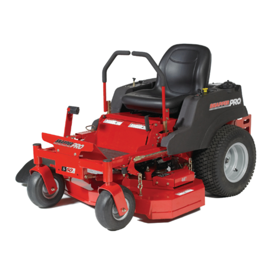
S50XBS2648, 26HP Briggs & Stratton, 48" Cut Zero-Turn Riding Mower
S50XKAV1948, 19HP Kawasaki, 48" Cut Zero-Turn Riding Mower
S50XBS2648 CAL, 26HP Briggs & Stratton, 48" Cut Zero-Turn Riding Mower
S50XKAV1936OS, 19HP Kawasaki, 36" Cut Zero-Turn Riding Mower
S50XBS2636, 26HP Briggs & Stratton, 36" Cut Zero-Turn Riding Mower
S50XKAV1936 CAL, 19HP Briggs & Stratton, 36" Cut Zero-Turn Riding Mower
S50XKAV2036, 20HP Kawasaki, 36" Cut Zero-Turn Riding Mower
S50XKAV2048, 20HP Kawasaki, 48" Cut Zero-Turn Riding Mower
S50XB2448, 24HP Briggs & Stratton, 48" Cut Zero-Turn Riding Mower
OPERATOR'S
MANUAL
S50X Series
Zero-Turn Riding Mower
5101098
Revision H
Advertisement
Table of Contents
Troubleshooting

Related Manuals for Snapper Pro S50X Series


Summary of Contents for Snapper Pro S50X Series
- Page 1 OPERATOR’S MANUAL S50X Series Zero-Turn Riding Mower Model Number: Description 5900709 S50XBS2648, 26HP Briggs & Stratton, 48” Cut Zero-Turn Riding Mower 5900734 S50XKAV1948, 19HP Kawasaki, 48” Cut Zero-Turn Riding Mower 5900743 S50XBS2648 CAL, 26HP Briggs & Stratton, 48” Cut Zero-Turn Riding Mower 5900769 S50XKAV1936OS, 19HP Kawasaki, 36”...
- Page 2 Thank you for purchasing this quality-built Snapper Pro product. We’re pleased that you’ve placed your confidence in the Snapper Pro brand. When operated and maintained according to the instructions in this manual, your Snapper Pro product will provide many years of dependable service.
-
Page 3: Table Of Contents
Table of Contents Operator Safety ............2 Safety Rules and Information ...........2 Safety Decals ..............8 Safety Interlock System ............9 Features & Controls ..........10 Identification Numbers ...........10 Control Functions ............11 Operation ..............13 General ................13 Checks Before Starting ...........13 Checking Tire Pressures ..........14 Seat Adjustment .............14 Mowing Height Adjustment ..........15 Foot Pedal Adjustment ............15... -
Page 4: Operator Safety
Operator Safety Operator Safety Safety Rules and Information Operating Safety Congratulations on purchasing a superior-quality piece of lawn and garden equipment. Our products are designed and manufactured to meet or exceed all industry standards for safety. Do not operate this machine unless you have been trained. Reading and understanding this operator’s manual is a way to train yourself. - Page 5 Operator Safety Slope Operation Operation on slopes can be dangerous. Using the unit on a slope that is too steep where you do not have adequate wheel traction (and control) can cause sliding, loss of steering, control, and possible rollover. You should not operate on a slope greater than a 5.4 foot rise over a 20 foot length (15 degrees).
- Page 6 Operator Safety Retaining Walls, Drop-offs, and Water Retaining walls and drop-offs around steps and water are a common hazard. Give yourself a minimum of two mower widths of clearance around these hazards and hand-trim with a walk behind mower or string trimmer. Wheels dropping over retaining walls, edges, ditches, embankments, or into water can cause rollovers, which may result in serious injury, death, or drowning.
- Page 7 Operator Safety Read these safety rules and follow them closely. Failure to obey these rules could result in loss of control of unit, severe personal injury or death to you, or bystanders, or damage to property or equipment. This mowing deck is capable of amputating hands and feet and throwing objects.
- Page 8 Operator Safety 2. Do not turn on slopes unless necessary, and then, turn WARNING slowly and gradually uphill, if possible. Never mow down slopes. It is a violation of California Public Resource Code, 3. Do not mow near drop-offs, ditches, or embankments. Section 4442, to use or operate the engine in any The operator could lose footing or balance or mower forest-covered, brush-covered, or grass-covered land...
- Page 9 Operator Safety Service and Maintenance 11. Stop and inspect the equipment if you strike an object. Repair, if necessary, before restarting. To avoid personal injury or property damage, use extreme care 12. Park machine on level ground. Never allow untrained in handling gasoline.
-
Page 10: Safety Decals
Operator Safety Safety Decals This unit has been designed and manufactured to provide you with the safety and reliability you would expect from an industry leader in outdoor power equipment manufacturing. Although reading this manual and the safety instructions it contains will provide you with the necessary basic knowledge to operate this equipment safely and effectively, we have placed several safety labels on the unit to remind you of this important information while you are operating... -
Page 11: Safety Interlock System
Operator Safety Safety Icons The alert symbol is used to identity safety information about hazards that can result in personal injury. A signal Safety Interlock System word (DANGER, WARNING, or CAUTION) is used with the alert symbol to indicate the likelihood and the potential severity of the injury. -
Page 12: Features & Controls
Features and Controls Features and Controls Identification Numbers When contacting your authorized dealer for replacement parts, service, or information you MUST have these numbers. Record your part number, serial number and engine serial numbers in the space provided on the inside front cover for easy access. -
Page 13: Control Functions
Features and Controls Figure 2. Control Locations Control Functions The information below briefly describes the function of individual controls. Starting, stopping, driving, and mowing require the combined use of several controls applied in specific sequences. To learn what combination and sequence of controls to use for various tasks see the OPERATION section. Seat Adjustment Lever Ground Speed Control Levers The seat can be adjusted forward and back. - Page 14 Features & Controls Parking Brake Fuel Tank Cap To remove the cap, turn counterclockwise. DISENGAGE Releases the parking brake. Fuel Level Gauge ENGAGE Locks the parking brake. Displays the fuel level in the tank. Pull the parking brake lever up to engage the parking brake.
-
Page 15: Operation
Operation Operation General Operating Safety WARNING Before first time operation: Never operate on slopes greater than 15°. • Be sure to read all information in the Safety and Select slow ground speed before driving onto Operation sections before attempting to operate this a slope. -
Page 16: Checking Tire Pressures
Operation Check Tire Pressures Tire pressure should be checked periodically, and maintained at the levels shown in the chart. Note that these pressures may differ slightly from the “Max Inflation” stamped on the side-wall of the tires. The pressures shown provide proper traction, improve cut quality, and extend tire life. -
Page 17: Mowing Height Adjustment
Operation Mowing Height Adjustment The cutting height adjustment pin (A, Figure 6) controls the mower cutting height. The cutting height is adjustable between 1-1/2” (3,37 cm) and 4-1/2” (11,47 cm) in 1/4” (0,64 cm) increments. 1. Depress the deck lift foot pedal (B) until it locks into the 4-1/2”... -
Page 18: Starting The Engine
Operation Pushing the Rider By Hand Starting the Engine NOTICE WARNING DO NOT TOW RIDER If you do not understand how a specific control Towing the units will cause transmission functions, or have not yet thoroughly read the damage. Do not use another vehicle to push or FEATURES &... -
Page 19: Zero Turn Driving Practice
Operation Zero Turn Driving Practice Smooth Travel The lever controls of The lever controls of the Zero Turn rider are responsive, and the Zero Turn rider are learning to gain a smooth and efficient control of the rider’s responsive. forward, reverse, and turning movements will take some practice. - Page 20 Operation Practice Turning Around a Corner Practice Turning In Place While traveling forward allow one lever to gradually return To turn in place, “Zero Turn,” gradually move one ground back toward neutral. Repeat several times. speed control lever forward from neutral and one lever back from neutral simultaneously.
-
Page 21: Mowing
Operation Mowing 1. Engage the parking brake. Make sure the PTO switch is disengaged, the ground speed control levers are locked in the NEUTRAL position and the operator is on the seat. 2. Start the engine (see Starting The Engine). 3. -
Page 22: Mowing Methods
Operation When and How Often to Mow The time of day and condition of the grass greatly affect the results you’ll get when mowing. For the best results, follow these guidelines: 1. Mow when the grass is between three and five inches high. -
Page 23: Attaching A Trailer
Operation Attaching A Trailer Proper Mulching Mulching consists of a mower deck which cuts and recuts The maximum weight of a towed trailer should be less than clippings into tiny particles and which then blows them 200 lbs (91kg). Secure the trailer with a appropriately sized down INTO the lawn. -
Page 24: Regular Maintenance
Regular Maintenance Regular Maintenance Maintenance Schedule The following schedule should be followed for normal care of your rider and mower. You will need to keep a record of your operating time. Determining operating time is easily accomplished by observing the elapsed time recorded by the hour meter. Safety Items Before Every 5... -
Page 25: Checking/Adding Fuel
Regular Maintenance Engine Maintenance Checking / Adding Fuel Refer to the engine owner’s manual for all engine To add fuel: maintenance procedures and recommendations. 1. Remove the fuel cap. 2. Fill the tank to about 1-1/2” (3,81 cm) of the bottom of the filler neck. -
Page 26: Lubrication
Regular Maintenance Lubrication Lubricate the unit at the locations shown in Figures 20 through 23 as well as the following lubrication points. Grease: • front caster wheel axles & yokes • deck lift pivot blocks • mower deck spindles • mower deck idler arm Use grease fittings when present. -
Page 27: Check Transmission Oil Level
Regular Maintenance Check / Fill Transmission Oil Oil Type: 20W-50 conventional detergent motor oil. 1. Check the oil level when the unit is cold. Locate the transmission oil reservoirs (A, Figure 24) located on the seat support plate. The oil should be up to the “FULL COLD”... -
Page 28: Servicing The Mower Blades
Regular Maintenance Servicing The Mower Blades Removing the Mower Blade CAUTION Avoid injury! Mower blades are sharp. • Always wear gloves when handling mower blades or working near blades. 1. To remove the mower blade, use a 1” wrench on the flats of the spindle shaft and remove the mower blade mounting bolt with a 15/16”... - Page 29 Regular Maintenance Sharpening the Mower Blade CAUTION Avoid injury! Mower blades are sharp. • Always wear gloves when handling the mower blades. • Always wear safety eye protection when grinding. 1. Sharpen the mower blades with grinder, hand file, or Figure 29.
-
Page 30: Ground Speed Control Lever Adjustment
Regular Maintenance Ground Speed Control Lever Adjustment The control levers can be adjusted in three ways. The alignment of the control levers, the placement of the levers (how close the ends are to one another) and the height of the levers can be adjusted. To Adjust the Handle Alignment Loosen the mount bolts (A, Figure 32) and pivot the lever(s) (B) to align with each other. -
Page 31: Parking Brake Adjustment
Regular Maintenance Parking Brake Adjustment 1. Disengage the PTO, stop the engine, engage the parking brake, and remove the key from the ignition. 2. Raise the seat plate to gain access to the parking brake components. 3. Measure the distance from the top of the brake spring rod (C, Figure 34) to the top of the lock nut (D) on both sides of the unit. -
Page 32: Return To Neutral Adjustment
Regular Maintenance 3. Lock the jam nut (A) against the ball joint when neutral is Return-to-Neutral Adjustment achieved. To determine if it is necessary to adjust the neutral return, 4. Pull the ground speed control lever rearward and release perform the following steps. to check position again. -
Page 33: Deck Rod Timing Adjustment
Regular Maintenance Deck Rod Timing Adjustment 1. Park the machine on a flat, level surface. Disengage the PTO, engage the parking brake, turn off the engine, and remove the ignition key. Rear tires must be inflated to 15 psi (1,03 bar); front tires to 40 psi (2,76 bar). 2. - Page 34 Regular Maintenance Deck Leveling Adjustment NOTE: Before adjusting the deck level, the deck lift rod timing must be checked and/or adjusted. 1. Park the machine on a flat, level surface. Disengage the PTO, stop the engine and engage the parking brake. Rear tires must be inflated to 15 psi (1,03 bar);...
-
Page 35: Mower Belt Replacement
Regular Maintenance Mower Belt Replacement NOTICE To avoid damaging belts, DO NOT PRY BELTS OVER PULLEYS. 1. Park the tractor on a smooth, level surface such as a concrete floor. Disengage the PTO, engage the parking brake, turn off the engine, and remove the ignition key. 2. - Page 36 Regular Maintenance Check the Mower Belt Idler Tensioner Spring Length 1. Park the machine on a smooth level surface such as a concrete floor. Disengage the PTO, engage the parking 7” brake, turn off the engine and remove the ignition key. (17,8 cm) 2.
-
Page 37: Hydraulic Pump Drive Belt Replacement
Regular Maintenance tension. Hydraulic Pump Drive Belt 5. Remove the old belt and replace it with the new one. Replacement Make sure the V-side of the belt runs in the grooves of 1. Park the tractor on a smooth, level surface such as a the crankshaft pulley and the transmission pulleys (B &... -
Page 38: Battery Maintenance
Regular Maintenance Battery Maintenance NOTE: This unit is equipped with a maintenance-free BCIU1 battery. Cleaning the Battery and Cables WARNING Be careful when handling the battery. Avoid spilling electrolyte. Keep flames and sparks away from the battery. When removing or installing battery cables, disconnect the negative cable FIRST and reconnect it LAST. -
Page 39: Battery Service
Regular Maintenance Battery Service Jump Starting With Auxiliary (Booster) Battery Jump starting is not recommended. However, if it must be Checking Battery Voltage done, follow these directions. Both booster and dis-charged batteries should be treated carefully when using jumper WARNING cables. - Page 40 Regular Maintenance THIS HOOK-UP FOR NEGATIVE GROUND VEHICLES Starter Starter Switch Switch Jumper Cable Starting Discharged Vehicle Vehicle Battery Battery Jumper Cable To Ground Engine Block MAKE CERTAIN VEHICLES DO NOT TOUCH Figure 45. Jump Starting WARNING WARNING Any procedure other than the preceding could result in: For your personal safety, use extreme care when jump starting.
-
Page 41: Storage
Regular Maintenance Storage WARNING Temporary Storage (30 Days Or Less) Never store the unit, with gasoline in engine or fuel tank, in a heated shelter or in enclosed, poorly Remember, the fuel tank will still contain some gasoline, so ventilated enclosures. Gasoline fumes may reach an never store the unit indoors or in any other area where fuel open flame, spark or pilot light (such as a furnace, vapor could travel to any ignition source. -
Page 42: Troubleshooting
Troubleshooting Troubleshooting Troubleshooting Chart WARNING While normal care and regular maintenance will extend To avoid serious injury, perform maintenance on the the life of your equipment, prolonged or constant use may tractor or mower only when the engine is stopped and eventually require that service be performed to allow it to the parking brake engaged. -
Page 43: Troubleshooting The Mower
Troubleshooting Rider Troubleshooting Continued. Problem Cause Remedy Transmission release lever(s) 1. Move the transmission release lever(s) to Engine runs, but rider will in “open” position. the “closed” position. not drive. Belt is broken. 2. See Drive Belt Replacement. Drive belt slips. 3. -
Page 44: Troubleshooting Common Cutting Problems
Troubleshooting TROUBLESHOOTING COMMON CUTTING PROBLEMS PROBLEM CAUSE REMEDY Streaking 1. Sharpen your blades. 1. Blades are not sharp. 2. Replace your blades. 2. Blades are worn down too far. 3. Always mow at FULL throttle. 3. Engine speed is too slow. 4. -
Page 45: Specifications
Specifications Specifications NOTE: Specifications are correct at time of printing and are subject to change without notice. ENGINE: TRANSMISSIONS: HydroGear ZL-KMEF-3L7C-1KLX (LH) HydroGear ZL-GMEF-3L7B-1KLX (RH) 19 HP Kawasaki ZT3100 Type Kawasaki Make SAE 20W-50 motor oil Hydraulic Fluid FH580V Model Forward: 0-7 MPH (0-11,27 km/h) Speeds Horsepower... -
Page 46: Slope Identification Guide
www.SnapperPro.com... - Page 47 Snapper Pro dealer during the warranty period. Snapper Pro' obligation under this limited warranty is, at Snapper Pro' option, to repair or replace any part or parts of the mower, which, in the judgment of Snapper Pro, are found to be defective and covered by this limited warranty.
- Page 48 OPERATOR’S MANUAL S50X Series Zero-Turn Riding Mower Briggs & Stratton Power Products Group, LLC. 5375 North Main Street Munnsville, NY 13409 800-933-6175 www.SnapperPro.com...
Need help?
Do you have a question about the S50X Series and is the answer not in the manual?
Questions and answers
Type transmission oil s50x
The recommended transmission oil for the Snapper Pro S50X Series is SAE 20W-50 motor oil.
This answer is automatically generated
how to adjust deck height on st50x
To adjust the deck height on the Snapper Pro S50X Series:
1. Depress the deck lift foot pedal (B) until it locks in the 4-1/2” (11,47 cm) position.
2. Place the cutting height adjustment pin (A) in the desired cutting height.
3. Depress the deck lift foot pedal again and push the lock lever (C) to the right to release the lock.
4. Release the deck lift foot pedal until it rests against the cutting height adjustment pin.
This answer is automatically generated