Tekmar 1873-ESM Installation And Adjustment Instructions
Ice and snow detector single unit configuration
Hide thumbs
Also See for 1873-ESM:
- Installation and adjustment instructions (88 pages) ,
- Quick start manual (4 pages)

Related Manuals for Tekmar 1873-ESM


Summary of Contents for Tekmar 1873-ESM
- Page 1 Ice and Snow Detector 1873-ESM, Single Unit Configuration Installation and Adjustment Instructions...
-
Page 2: Table Of Contents
For the “System” and “Multi Channel” configu- Connection diagram ........11 rations, refer to the complete documentation Required settings........... 12 “Ice and Snow Detector 1873-ESM and 1875- ESM” (ME-1873~5-ESM-EN). Further basic settings ........12 User interface ..........14 Settings ............21 Troubleshooting ........ - Page 3 Scope of delivery Ice and Snow Detector 1873-ESM Installation and Adjustment In- structions: Ice and Snow Detector 1873, Single Unit Configuration Safety instructions tekmar pencil (Rubber end can be used to operate the touch display)
-
Page 4: Overview
It is operated and adjusted via an illuminated touch graphic display, which is also used to set the para- Tekmar ice detection systems use their combi sen- meters of all the other devices in a system. A three- sors to measure temperature and moisture in... - Page 5 Overview Documentation with axial cable connection. Both sensors are characterised by a compact and robust design, Other relevant documentation: which is achieved by the casing made of high- Safety instructions quality, corrosion-resistant brass and the microbe- I-187x-ESM-Sensor-EN, proof, longitudinally watertight cable. summarised extract from M-MES-Sensorik The sensors can be used for a wide variety of re- (Installation instructions for sensors of the T,...
-
Page 6: Terms And Functions
Terms and functions Operating mode The basic operation of an ice detection channel can Ice detection channel be selected via the operating mode. An ice detection channel is a unit consisting of a Temp. Moisture heating circuit with its output relay, a combi sensor This is the normal operating mode of an ice de- and the associated evaluation logic. - Page 7 Terms and functions Activation temperature (upper temperature limit) is dry, the moisture threshold should be increased. If the system switches on the heating system too If the temperature of the combi sensor - and thus of late, the moisture threshold should be reduced. the heated area - falls below the defined activation temperature, the moisture measurement will be ac- Note: If the moisture threshold is too low, the...
- Page 8 Terms and functions The system automatically optimises the duration of frosted. During the minimum heating time, no fur- a measuring cycle depending on the sensor type ther moisture measurement takes place. and temperature. An external button on input A, which is switched to Switch-off temperature (lower temperature limit) L, can be used to manually activate the defined minimum heating time.
- Page 9 Terms and functions In case of an error in the combi sensor additionally this function is not guaranteed and an error mes- an alarm will be triggered. If only the moisture unit sage may occur. is affected by the sensor error, the emergency Alarm management mode will only be activated if the temperature is The alarm management of the 1873 monitors the...
-
Page 10: Installation And Commissioning
Installation and commissioning Installation procedure Only qualified personnel (electrician or Proper use similar qualification) may install the device. The device must only be used for the control relevant engineering practices electric water-operated heating enclosed safety instructions must be observed! systems. It has to be installed in an electric distribu- Disconnect the control cabinet before installation. -
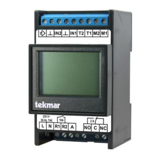
Page 11: Connection Diagram
The weather sensor is used to gather information on the outside tempera- ture for the base temperature and the pre-heating modes. For further information, refer to the complete docu- mentation for the 1873-ESM and 1875-ESM (ME- 1873~5-ESM-EN). -
Page 12: Required Settings
Service → ISD channel → Channel” applications, refer to refer to the Start moisture measurement? complete documentation for the 1873-ESM 3. Add 1.0 to 2.0 to the determined moisture value and 1875-ESM. depending on the desired sensitivity and set this value as the moisture threshold. - Page 13 Installation and commissioning Upper temperature limit Idle display Operation Adjustment of the upper temperature limit valid for the ice detector or the selected ice detection chan- nel. Also refer to Activation temperature, page 7. Password protection Menu → Information → Set passwords If required, password protection can be set for different menu levels.
- Page 14 Recommended components: guaranteed. This unintended application does not always work reliably. Relay interface module tekmar has, with no obligation, developed and test- Manu- Article Type ed a solution for a correct function, also in connec-...
- Page 15 Installation and commissioning...
-
Page 16: User Interface
User interface Menu launch menu >> next menu level Touch display with softkey buttons << one menu level back The touch display of the 1873 may be operated by next (to select one of several parame- > using up to four softkeys at the bottom of the ters) screen, pressing them either with the finger or the back (to select one of several param-... - Page 17 User interface Menu structure Numeric keypad The individual menu items are explained in detail in the chapters Settings and Operation. The menu items under Menu → Installer are reserved for the qualified installation technician. Some settings appear under several menu items because this will save time jumping back and forth in different menu levels during installation.
- Page 18 User interface Menu Level 1 Level 2 Level 3 Level 4 Page Operation Operating mode Upper temperature limit Moisture threshold Minimum heating time Start minimum heating time? Information Channel state Temperature moisture area Last moisture measure- ment Remaining heating time Operating time Energy consumption Device data...
- Page 19 User interface Installer Startup Application Sensor type Information Channel state Error code Temperature heating area Last moisture measure- ment Remaining heating time Remaining inhibition time moisture Operating time Operating time total Energy consumption Energy consumption total Device data Serial number Version Config.
- Page 20 User interface PWM interval time Emergency duty cycle Alarm delay Alarm relay inverted Emergency mode with error temperature Blocking protection active Operating time: Reset counters Service ISD channel Start minimum heating time? Stop heating? Start moisture measure- ment? Sensor temperature Last moisture measure- ment Remaining inhibition time...
-
Page 21: Settings
Settings Operating mode Operation | Installer → Config. modules Adjustment of the operating mode for the ice detector or the selected ice detection channel. For further information on the operating modes, also refer to Operating mode, page 6. Factory setting: Temp.Moisture, possible settings: Off, Temp.Moisture, Temperature, Emergency op. - Page 22 Settings Minimum heating time Operation | Installer → Config. modules Adjustment of the minimum heating time for the ice detector or the selected ice detection channel. The minimum heating time is started once moisture is detected in standby mode. Also refer to Minimum heat- ing time, page 8.
- Page 23 Settings Last moisture measurement Information | Installer → Information | Installer → Service → ISD channel Display of the last measured moisture value. The higher the value, the more moisture was on the sensor surface during the measurement. Also refer to Moisture measurement, page 7. Possible values: undefined, 0.0 to 10.0.
- Page 24 Settings Version Information → Device data | Installer → Information Display of the software version and build number (four digits). Set passwords Information Possibility to set up password protection. For a detailed description refer to Password protection, page 30. Factory setting: 0000 for levels 1, 2 and 3 Language Setup Adjustment of the menu language.
- Page 25 Installer → Startup The application must be set to “Single Unit. For further information on the applications “System” and “Multi Channel”, refer to the complete documentation for the 1873-ESM and 1875-ESM. Sensor type Installer → Startup | Installer → Config. modules Adjustment of the type of combi sensor connected to the respective ice detection channel.
- Page 26 Settings Operating time total Installer → Information Display of the total operating hours a heating circuit has accumulated since the device has last been reset to its factory settings. Energy consumption total Installer → Information Display of the total heating energy used since the device has last been reset to its factory settings. This value is the product of the heating output and the value of the resettable operating time counter (in kWh).
- Page 27 Settings Lower temperature limit Installer → Config. modules Adjustment of the lower temperature limit for the channel. Also refer to Switch-off temperature, page 8. Factory setting: -15 °C, possible settings: -30 to -5°C Follow up time Installer → Config. modules Adjustment of the follow up time.
- Page 28 Settings Emergency duty cycle Installer → Config. modules Adjustment of the duty cycle (i.e. the time during which the heating is switched on in relation to the interval time) of the PWM in emergency operation. For further notes refer to Emergency mode, page 8. Factory setting: 0 %, possible settings: 0 to 100 % If >...
- Page 29 Settings Stop heating? Installer → Service → ISD channel Possibility to switch off the heating during an ongoing minimum heating time. Factory setting: No, possible settings: No, Yes Start moisture measurement? Installer → Service → ISD channel Activation of a moisture test measurement for the combi sensor allocated to the ice detection channel, inde- pendent from the current ground temperature.
- Page 30 Password protection order to regain access. In the retail partner’s area Information → Set passwords on the tekmar website, the device's serial number can be entered and the super password retrieved. Passwords can be set for three menu levels (Level...
-
Page 31: Troubleshooting
Troubleshooting Display Codes Error codes and alarm messages Position Position 1 - 4 Installer → Information 1 - 4 In case of an error the alarm relay is activated and an alarm is raised. The corresponding error code is shown on the display in idle mode and can also be found under the above menu items. - Page 32 Voltage at sensor cannot be measured. Check sensor connection. If not successful, return device to the measurement tekmar Service to be checked. E xx1x error current Current through sensor cannot be measured or current is too low for measurement the defined sensor type.
- Page 33 This indicates an mode error in the device. Return device to the tekmar Service to be checked. E xx4x error upon start Error when moisture measurement is started. Possible reasons:...
- Page 34 Troubleshooting Error code Description Explanation/measure E x2xx error heating Monitoring of the heating output signals an error, i.e. it may be that output the heating element could not be switched on/off. In parallel to the relay in the device there is an electrical circuit which continuously monitors the output (even when switched off).
- Page 35 "Emergency mode" can be manually Only if the same error persists after the power has set as the operating mode. been switched on again, contact the tekmar Service. Note: In the Emergency mode, heating takes place regardless of the prevailing temperatures. Depend- ing on the set control value, this can result in high electricity costs.
- Page 36 3354 77 to 94 temperature unit. 3356 71 to 81 Ω Ω Ω °C °C °C Further information on troubleshooting can be found 32,197 8,941 2,970 under: www.tekmar.de. 24,532 7,070 2,431 18,851 5,634 2,000 14,616 4,520 1,657 11,383 3,652 1,379...
-
Page 37: Technical Data
Technical data Ice and Snow Detector 1873-ESM Moisture sensor/combi sensor: tekmar Type 3354, 3356 (or 3355 with conversion kit) Optional temperature sensor: tekmar Series 31, e. g. 3154 Temperature measuring range: -30 °C to +80 °C Load output/primary relay: - potential-free normally open contact... - Page 38 Technical data Protection class: II if installed properly Area of operation: up to 2000 m above sea level Enclosure: rail-mounted device 3 HP (according to DIN 43880) Mounting: mounting rail TH-35 according to DIN EN 60715 Weight: approx. 0.25 kg Heat and fire resistance: Category B/D Ball pressure test:...
- Page 39 Technical data Dimensions Regulations The product corresponds to the following rules and regulations: EMC Directive Radio Equipment Directive Low-voltage Directive RoHS Directive WEEE-Reg.-No.: DE 75301302...
-
Page 40: Available Accessories
Ground installation socket for sensor 3355/3356 Gutter sensor 3354 for combined measurement of moisture and temperature values Mounting plate for sensor 3354 (copper or zinc) Conversion kit for ground sensor 3355 in case of replacement of an old tekmar ice and snow system 1773... - Page 41 Notes...
- Page 42 Notes...
- Page 43 Notes...
- Page 44 Regelsysteme GmbH Möllneyer Ufer 17 D-45257 Essen mail@tekmar.de www.tekmar.de <ME-1873E-ESM-EN> Status 2022-09 Subject to change without notice © 2022 tekmar Regelsysteme GmbH...
Need help?
Do you have a question about the 1873-ESM and is the answer not in the manual?
Questions and answers