Advertisement
D 194.8
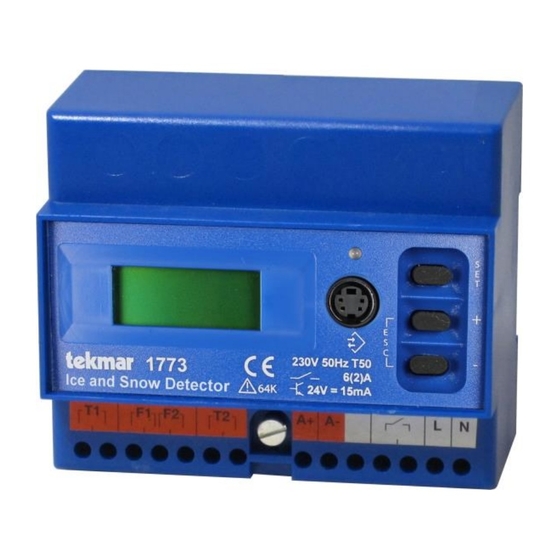
Ice and Snow Detector Type 1773
for the TF-E System
Introduction
In cooperation with the moisture and temperature sensors of the TF-E system, the 1773 Ice and Snow Detector
is used for early detection of ice and snow and for keeping the monitored surface or gutter free by switching on
a defrosting device. One or two sensors can be connected to the 1773 Ice and Snow Detector. The sensor
function (temperature and/or moisture monitoring) and other settings can be defined for each sensor
individually. The individual parameters and measured values can be diplayed and changed in the menu using
the display and three operating buttons. An LED shows the current operating state.
The sensor type 3354 (or its predecessor 3351) can be used for gutters, flat rooftops or satellite systems. Open
areas such as driveways or parking lots can be monitored with the sensor types 3355 and 3356 (predecessors
3352 and 3353), which resist mechanical load such as cars driving over them.
Most ice and snow detection systems use exposed metal electrodes. Their disadvantage is that these
electrodes can accumulate dirt, suffer from corrosion or get short circuited by external conductive objects.
Therefore their sensors need periodical maintenance work in order to avoid that environmental influences impair
the accuracy of moisture measurement.
The TF-E system takes advantage of the increase of thermal capacity due to moisture, i. e. the availability of
water in liquid or solid form (snow, ice) on the sensor. With the help of a patented measurement and evaluation
method, the temperature variation with regard to the sensor is used to detect moisture on the sensor surface.
This guarantees a maintenance-free and secure operation.
Content
1. Functions
1. Functions
If the sensor temperature is below the defined critical temperature limit, the moisture control is activated. If
moisture is detected, the heating system is switched on. If not, the moisture is measured again periodically. At
the earliest when the defined minimum heating time has expired, the heating system is switched off again if
there is no more moisture on the sensor.
In addition to the limit value of the critical temperature range (0 to +5 °C) a lower value can be set between -5
and -20 °C. This is useful because in case of very low outdoor temperatures there will no longer be any dripping
melt water or snow. If snow falls despite the extreme temperature, it will be dry, light and not slippery. In such a
case the heating would not be powerful enough to completely melt the snow on the surface. Thus the danger of
slippery conditions would rather be increased if the heating were switched on.
- 1 -
Advertisement

Related Manuals for Tekmar 1773


Summary of Contents for Tekmar 1773
-
Page 1: Table Of Contents
One or two sensors can be connected to the 1773 Ice and Snow Detector. The sensor function (temperature and/or moisture monitoring) and other settings can be defined for each sensor individually. - Page 2 Connecting the sensor inputs In order to adapt to the desired monitoring functions, you can choose to wire the inputs in three different ways: Operation with one sensor The Type 33.. sensor is connected to sensor input 1 for temperature and moisture monitoring. Operation with two sensors Two sensors can be connected to the ice and snow detector: either two combi sensors for moisture/temperature or one combi sensor and one temperature sensor.
-
Page 3: Sensor Mounting In Open Areas
As soon as the outdoor temperature is below the high temperature limit (within the range of the "high and low temperature limit"), the slab temperature measured by the sensor at input 1 is kept at the level of the setpoint value (with an hysteresis of ... - Page 4 When choosing the sensor's installation location, unfavourable circumstances such as aisles, shady areas, warm air outlets in underground parking lots etc. need to be avoided. The sensor should be installed in a place where the critical criteria "moisture and low temperature” causing the formation of ice are most likely to occur first.
- Page 5 Installation example with two sensors Two sensors can be connected to the snow and ice detector. In this way it is possible to optimally monitor large or separated open areas, which may have different local conditions (such as sun in the southern part of the area and shadow in the northern part or due to shading by a roof as in the illustration below).
-
Page 6: Sensor Mounting In Gutters, On Rooftops And On Satellite Systems
Technical data: Types 3352, 3353, 3355, 3356 Supply line: SL-Y11Y, length 6 m, 20 m, 50 m resistant to microbes and oil according to DIN VDE 0472/9.21 para. 8036 Degree of protection: IP 68 –30 ...+75 °C Temperature resistance: Sensor 3352/3353 Sensor 3355 Sensor 3356 Length of supply lines... - Page 7 Installation location in the gutter The sensor has to be installed below the drip edge and close to the downpipe in such a way that melt water drips on the sensor. The heating cables, which are also installed in the lower part of the roof surface in the example on the right, ensure that a sufficient area inside and above the gutter are kept free from snow and ice.
-
Page 8: Connection Diagrams
4. Connection diagrams Note for service cases: The sensors are delivered with a four-wire cable. In existing installations there may be sensors with a five-wire cable. Note that in this case the black wire is not connected. Important commissioning note related to wiring The ice and snow sensors of the T-FE series come with a four-core cable. - Page 9 Prior to powering up it is strongly recommended to check the wiring at the sensor terminals of the socket with an ohmmeter before plugging the controller into the socket. The expected electrical resistance values can be found below in the instructions in section "Characteristic values of sensors". With a single sensor connected, perform the checks shown in the left column of the table, and with two sensors connected perform the checks in both columns.
-
Page 10: Commissioning
5. Commissioning Setting the language When the ice and snow detector is switched on for the first time, you will be asked to set the language for the menu navigation. This language will be used as the menu language and saved as a factory default setting. The language can be selected with the help of the '+' and '-' keys. -
Page 11: Display And Pushbutton Functions
6. Display and pushbutton functions Operating state indicator The display on the front shows the following operating states: Green flashing System initialization Green System in service Green/red flashing System in service, at least one sensor faulty (alarm active) Red flashing System not in service (alarm active) System manually switched off Pushbutton functions... - Page 12 Direct functions Manual activation/deactivation of the slab heating From the home display the heating can be activated by pressing the"+" pushbutton for a least two seconds. The heating duration corresponds to the minimum heating time. If the heating has already been active, the remaining heating time will be reset to the minimum heating time.
- Page 13 Home display Menu level 1 Menu level 2 Menu level 3 Explanation Last Display: last moisture value Moist. -x InhibTim Display: inhibit time for temperature Tmp. ..m measurement InhibTim Display: inhibit time for moisture MDet. ..m measurement back back Test HeatTime Command: start/stop for minimum Test...
- Page 14 Menu structure 1. Home display Display Explanation +xx° yyy xx = effective slab temperature zzzzzzzz yyy = remaining minimum heating time (0 if heating according to demand or heating off) zzzzzzzz = current state of the ice and snow detector 2.
- Page 15 Status Opens menu to display sensor n (after the first "Set" select n, Sensor n select sensor with "+" / "-" and then press "Set" again) Back Returns to Main menu 5. Test menu Display Explanation Displays the switching state of the slab heating; adapt setting with HeatTime "Set"...
- Page 16 setting with "Set" there will be a security prompt and after confirming with "+" an acknowledgement will be displayed (OK). SW-Vers. Displays the software version Internal Information only for the manufacturer Status Back Returns to Main menu 8. Status of slab heating Display Explanation Slab Heat.
- Page 17 -X to 95 Moisture Displays the set moisture limit for the selected sensor; adapt setting limit xx with "Set" and then "+" / "-"; save with "Set". Setting "-x" = the moisture limit set in the "Configuration" menu will be used.
- Page 18 Note: The sensor error codes 2, 4 and 8 will only be set during a moisture detection cycle and will remain visible at least until the completion of the next moisture detection cycle of the affected sensor. This is even the case if no more moisture detection cycles are started because the slab/gutter temperature is outside the active temperature window.
-
Page 19: Technical Data, Safety Instructions
The device can also be reset by switching the upstream circuit breaker off for approximately 10 seconds. In most cases the device functions without problems after the reset. If this is not the case, contact the tekmar Service. - 19 -... - Page 20 Notes tekmar Regelsysteme GmbH Tel +49 201 48611-0 mail@tekmar.de Möllneyer Ufer 17 Fax +49 201 48611-11 www.tekmar.de D-45257 Essen © Copyright tekmar Regelsysteme GmbH 2017, subject to change - 20 -...
Need help?
Do you have a question about the 1773 and is the answer not in the manual?
Questions and answers