Table of Contents
Advertisement
Quick Links
Advertisement
Table of Contents

Related Manuals for MICROPHASE Mini Dc


Summary of Contents for MICROPHASE Mini Dc
- Page 1 Mini Dc Service manual MICROPHASE Precision Servodrive for DC Motors Mini Dc Servo Amplifier for Brush DC Motors Eurocard Servodrive for Brush motors Service Manual MICROPHASE 36051 Creazzo (Vicenza) Italy Phone (+39) 0444 - 14.40.137 e-mail: info@microphase.eu www.microphase.eu...
-
Page 2: Table Of Contents
Mini Dc Service Manual Index Chapter 1 1.1 Safety and note ......................... 3 1.2 Operation mode and feedback ....................4 1.3 View product ..........................5 1.4 Model and size .......................... 6 1.5 Ambient conditions ........................7 1.6 Ventilation ..........................7-8 1.7 Dimensions .......................... -
Page 3: Safety And Note
Mini Dc Service manual Safety and note Caution Users must keep well clear in mind that this motion control equipment is capable of producing high forces and rapid movement so they must be used with attention especially during the application program’s development. -
Page 4: Operation Mode And Feedback
Mini Dc Service Manual 1.2 Operation mode and feedback Description This is a drive capable to drive DC brush motors, up to 9Nm. It's a High Performance full four quadrant drive servo amplifier. The mosfet output power stage is controlled by a 20 Khz PWM (Pulse Width Modulation) signal that allows it to drive servo motors where high dynamic performance and precise speed is required. -
Page 5: View Product
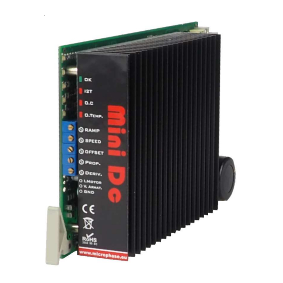
Mini Dc Service manual 1.3 View product Product ID Label Aluminum heatsink Leds Calibration Potentiometers Test point (V.tacho, I.Motor, GND) DIN 64 connector (32a+32c) pitch 2,54 Adjustement zone Adjustement settings 7 6 5 4 3 2 1 www.microphase.eu... -
Page 6: Model And Size
Mini Dc Service Manual 1.4 Model and size Model available POWER SUPPLY Model 65 19 - 84 Vdc* 60Vdc ** Model 145 39 - 184 Vdc* 140Vdc ** Model 205 54 - 276 Vdc* 200Vdc ** * Power supply min/max **Typical... -
Page 7: Ambient Conditions
Mini Dc Service manual Ambient conditions Cable duct Conductive mounting panel (zinc coated) Positioning in the electrical box Follow the instructions in the positioning of the servodrive in the electrical box. - The drive is natural convection air flow cooled. -
Page 8: Dimensions
Mini Dc Service Manual Supplementary ventilation Mounting position V = Standard radiator+fan cooling below the converter (operating temperature 0 to +45°C) 1.7 Mechanical dimensions Dimensions in mm www.microphase.eu... -
Page 9: Input And Output Signals
Mini Dc Service manual 2.1 Input and output signals The following description refers to the 64 pin DIN connector. Wire connections must be made in the terminal boards of the Panel mount and Rack supports. DIN 32a+32c CONNECTOR Signal Common Ground. Corrisponds to power supply's negative GND input (OUT) Fault drive, open collector output max. -
Page 10: Ground Gnd
Mini Dc Service Manual Input and output signals 2.2 Signal common ground GND (1ac) Signal Common Ground. Corrisponds to power supply’s negative GND power input (19ac, 20ac, 21ac, 22ac) 2.3 FAULT output (2ac) Fault drive, open collector output max. 100mA... -
Page 11: Current Limitation (Tprc)
Mini Dc Service manual Input and output signals 2.5 Current limitation TPRC (3ac) With an external potentiometer connected from GND and TPRC input, you have a limitation of output current (from zero to max. size) drive's. MINI DC External potentiometer (47K-100kOhm) 1-10 TURNS The speed loop remains active and uses the input reference signal +/-VEL. -
Page 12: Analog Velocity Input +/-Ref
Mini Dc Service Manual Input and output signals 2.7 Analog reference input +REF (6ac) The following diagram shows an application using speed reference connections from C.N.C in the Common Mode. This analog in common mode has a 20Kohm of impedance input. -
Page 13: Tachogenerator Input
Mini Dc Service manual Input and output signals 2.9 Tachogenerator input (9ac) When the motor have a tachogenerator you can use the terminal 9ac as input for this feedback. Connect this terminal to the negative of tachometer. 2.10 Current monitor output (11ac) On this terminal is available analog output "current monitor of motor"... -
Page 14: Internal Adjustements
Mini Dc Service Manual 3.1 Internal adjustements If changes need to made to the internal drive setting powering, please wait at least 20 seconds after the power has been removed and the OK LED is off. All of the personalizations are located inside of the DRIVE. (See figure above) -
Page 15: Adjustements With Tachogenerator Feedback
Mini Dc Service manual Setting with tachogenerator feedback In this configuration, the drive must set with the following Dip Switch and below internal setting: DS1 SWITCH ADJUSTEMENT PADS 7 6 5 4 3 2 1 DS1 Switch set for: Note: On the adjustement zone are not... -
Page 16: Adjustements With Armature Feedback
Mini Dc Service Manual 3.3 Setting with armature feedback In this configuration (Motor with only +M and -M armature), the drive must set with the following DS1 Switch and below internal setting: DS1 SWITCH ADJUSTEMENT PADS 7 6 5 4 3 2 1... - Page 17 Mini Dc Service manual RCA resistor calculations Insert an RCA resistor on the header (ajustement zone) to compensate for voltage loss due to the motor resistance reducing the loss of RPM. The formula is as follows: RCA (Kohm) = 0,49 * 1000 * Vmot...
-
Page 18: Adjustements With Encoder Feedback
Connections: Wire A of the encoder is connected to terminal CHA, wire B to terminal CHB to the rack- mount or panel-mounting installation kit. The encoder supply zero must be connected to the GND terminal. For details contact Microphase. www.microphase.eu... -
Page 19: Current Adjustments
Mini Dc Service manual Current adjustement RIP resistor (Peak current adjustment) RIP resistance limits the maximum current supplied by the converter. For the calculation see the following table: Value of RIP in Kohm Valore RIP 390 220 150 120 100 82... -
Page 20: Ramp Time Adjustments
Mini Dc Service Manual 3.6 Ramp time adjustement The product is standard setting with this feature is not enabled DS1 switch (2) and (3) OFF To enable the ramp acceleration close the DS1 switch 4. FUNCTION RANGE SETTING Ramp disabled... -
Page 21: Potentiometer Adjustments
Mini Dc Service manual Potentiometer adjustements The converter is equipped with five trimmer with the following meanings: FUNCTION Ramp adjustement. The DS1 switch 2, 3 and 4 select the acc/dec function (ramp). With this potentiometer we can adjust the slope of the acceleration and RAMP deceleration ramps. -
Page 22: Dynamic Adjustments
Mini Dc Service Manual 3.8 Dynamic adjustement The multi-turn PROP. and DERIV trimmer allow to dynamically tune of the motor and its mechanics linked to it. These trimmers have full excursion from minimum to maximum, with 15 turns of rotation of the same. -
Page 23: Indicator Leds And Protections
Mini Dc Service manual Indicator Leds and protections The protections are all displayed by four LEDs on the front of the drive. It also comes with a series of protections designed to safeguard in case of malfunction, the drive and the motor. - Page 24 Mini Dc Service Manual White page www.microphase.eu...
Need help?
Do you have a question about the Mini Dc and is the answer not in the manual?
Questions and answers