Table of Contents
Advertisement
Quick Links
Advertisement
Table of Contents

Related Manuals for MICROPHASE DC One DC1C Series


Summary of Contents for MICROPHASE DC One DC1C Series
- Page 1 Classic Service Manual MICROPHASE DC One servo drive Precision Servo drive for DC Motors Servoamplifier dc M otors Service Manual MICROPHASE 36051 Creazzo (Vicenza) Italy Phone (+39) 0444 - 14.40.137 e-mail: info@microphase.it www.microphase.eu...
-
Page 2: Declaration Of Conformity
Address: Via Palladio 23 36051 Creazzo (VI) Italy MICROPHASE s.a.s. assures that the drives listed above meet the following European Norms Standard: in accordance with EC Directive 2014/30/EU (EMC Directive) EN 55022, EN 61000-4-2 in accordance with EC Directive 2014/35/EU (Low Voltage Directive)) - Page 3 4.2 Brush motor Connections with Tachogenerator feedback ..........26-27 4.3 Brush motor Connections with Armature feedback ............28-29-30 4.4 Current adjustments ........................ 31 4.5 Ramp time adjustments ......................32 4.6 Potentiometer adjustments ..................... 33 4.7 Dynamic adjustments ......................34 4.8 Indicator Leds and protections ....................35 www.microphase.eu...
- Page 4 - Power off the drive and wait until all the leds are turned off before touching, removing, connecting or any other critical action. - Never disconnect any connectors before powering down the drive www.microphase.eu...
- Page 5 Closing the velocity feedback loop to motor may be done in several different ways to accommodate most applications. This types of velocity feedback are available with DC brush motors. • DC motor with encoder • DC motor with internal PWM (Armature) • DC motor with tachogenerator www.microphase.eu...
- Page 6 Minimum Inductance motor 400uH Weight 0,35kg 10.6oz Contaminants 2° or better (Norms EN60204 e EN50178) Up to 1000m without restrictions, from 1000 to 2000m Altitude power derating 1,5%/100m Cover material, the PCB and the electronic component Flammability rating 94V-0 meet 94V-0 www.microphase.eu...
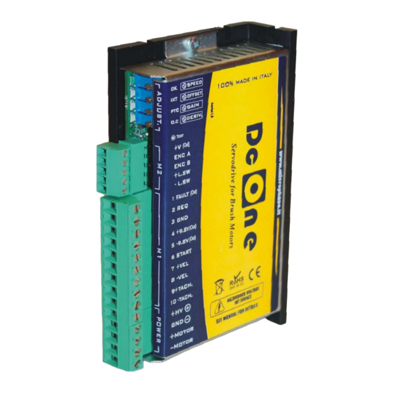
- Page 7 Four calibration Potentiometers Four Leds TEST point (Encoder, Tacho or Armature velocity) M2 Signal terminal 5 pins MC1,5/5-ST-3,81 (pitch 3,81) (10) M1 Signal terminal 10 pins GMST 2.5/10-G-5,08 (pitch 5,08) (11) POWER Terminal 4 pins GMST 2.5/5-G-5,08 (pitch 5,08) www.microphase.eu...
-
Page 8: Ambient Conditions
Supplementary ventilation may be requested in accordance to size. See the table below. SIZE MODEL 7/14 10/20 N = Standard radiator (operating ambient temperature from 0 to 40°C) V = Standard radiator + supplementary ventilation (operating ambient temperature from 0 to 45°C) (*) = Not available www.microphase.eu... -
Page 9: Mounting Position
Classic Service Manual Supplementary ventilation Mounting position V = Standard radiator+fan cooling below the converter (operating temperature 0 to +45°C) If you need the converter mounted horizontally, remove the cover. Mechanical dimensions Dimensions in mm and Inch www.microphase.eu... -
Page 10: Power Connector
Power connector POWER Positive Power supply input (IN) Negative Power Supply input (GND) (IN) +MOTOR Motor connection phase +M (OUT) -MOTOR Motor connection phase -M (OUT) NOTE: See also the connection diagrams in Chapters 4.1 - 4.2 - 4.3 www.microphase.eu... -
Page 11: Signal Inputs And Outputs
To enable this function, you must open the internal soldiering point SG and SH. See chapter 2.10 Counter-Clockwise (CCW) limit Switch input. (High logic level from >5V to - L.SW (IN) +24Vdc max). To enable this function, you must open the internal soldiering point SG and SH. See chapter 2.10 www.microphase.eu... -
Page 12: Fault Output
V(REQ) = 10 * Request current / PKcurrent Drive Example: (Drive size 10/20A, request current 8A) V(REQ) = 10 * 8 / 20 = 4V NOTE: In current reference the loop of internal velocity automatically excludes itself . www.microphase.eu... - Page 13 Increasing the ohmic value of resistance, the value of current supplied increases. With 47K of the current is limited to 50% on the Maximum size. The loop motor speed remains active. Signal common ground (M1 signal terminal pin 3) Signal Common Ground. Corrisponds to power supply’s negative GND input. www.microphase.eu...
-
Page 14: Start Input
Start enable input has logic range: >+9V to +30Vdc (min/max) DRIVE Unconnected Enable input = Drive Not Enabled Enable Input >+9V to +30Vdc = Drive Enabled Is possible enable the drive connected the START input with +9.8V output "terminal 4" www.microphase.eu... - Page 15 Common Mode. This analog in common mode has a 20Kohm of impedance input. DRIVE Speed reference from external potentiometer The following figure shows an application with speed reference connections using an internal +/-9.8V power supply. The speed potentiometer must have an included value between >5 and <10Kohm. Speed potentiometer DRIVE www.microphase.eu...
-
Page 16: Encoder Inputs
Encoder can be connected either push-pull (wires A, B and GND) or line-driver encoder type (wires + A + B and GND). Remember to connect the zero encoder with the GND power converter. View the connections and settings from encoder in chapter 4.1 www.microphase.eu... -
Page 17: Limit Switch Inputs
- DON'T connect any voltage in the +L.SW and -L.SW inputs if the soldiering point SG and SH are closed - When one of these said contacts is intercepted the motor stops with the required inertia. Fig. 1 Fig. 2 Example with external positive voltage (between +5Vdc and +24Vdc) www.microphase.eu... - Page 18 Classic Service Manual Limit switch inputs (continue) Example with internal positive voltage (+9.8V) Fig. 3 www.microphase.eu...
- Page 19 Where the Vdc motor is a sum of FCEM + the drop R*I for the winding resistance motor Vdc motor = E+(Ri * In) The FCEM of the motor "E", may be calculated by the formula: E = Ke * N° / 1000 www.microphase.eu...
- Page 20 Primary of the transformer: Use the formula below to calculate the correct values: F1 (A) = P (VA) trasfo. / V1 Secondary of the transformer: Use the table below FUSE F2 (A) SIZE Drive (A) 1/2 - 2/4 7/14 10/20 –12/24 www.microphase.eu...
- Page 21 Motor and Power cable (as norm EN60204) SECTION SIZE (A) 1,5mm / 15AWG 1/2 2/4 4/8 7/14 2,5mm / 13-14AWG 10/20 12/24 Control signals cable (as norm EN60204) SECTION 0,5mm / 20AWG Feedback signals cable (as norm EN60204) SECTION 0,25 - 0,35mm / 22 -24AWG www.microphase.eu...
-
Page 22: Multiple Connection
3) Use of shielded cables, both for power connection (to the transformer and the motor), and for signal connection (also to the controller). 4) Use of appropriate network to filter the line (transformer input), from disturbances conducted or produced by the drive. (series of filters released are available for this purpose) www.microphase.eu... - Page 23 The following pages highlight the various settings to be implemented over the area of adjustments to set the converter depending on the desired velocity feedback. In the left-hand page for each chosen velocity feedback, is shown a typical connection with the notes of wiring of the converter. www.microphase.eu...
- Page 24 To obtain good dynamic performance of the motor, we recommend the use of encoders with at least 2000/2048PPR. Acceptable performance is obtained anyway even with the use of encoders 500/512PPR. Is possible to use the +5V output "+V terminal" for the supplies the encoder. Note: the maximum load on terminal +V is 130mA. www.microphase.eu...
- Page 25 Once the resistor RENC is inserted, proceed with final speed adjustment. Operate using trimmer SPEED on the front of the drive. With Clockwise Rotation the speed increases. With Counter Clockwise Rotation the speed decreases. The Range of regulation is about +/- 25%. www.microphase.eu...
- Page 26 Signals from the encoder are connected only to the CNC for the control of space loop. This function is enabled through the following settings on the solder point, and the insertion of RDT resistance on the adjstustement zone. www.microphase.eu...
- Page 27 Once the resistor RDT is inserted, proceed with final speed adjustment. Operate using trimmer SPEED on the front of the drive. With Clockwise Rotation the speed increases. With Counter Clockwise Rotation the speed decreases. The Range of regulation is about +/- 25%. www.microphase.eu...
- Page 28 In the armature voltage PWM converter is used as the internal feedback of speed, when the motor has not an encoder. This function is enabled through the following settings on the solder point, and the insertion of RA and RCA resistance on the adjstustement zone. www.microphase.eu...
- Page 29 Once the resistor RA is inserted, proceed with final speed adjustment. Operate using trimmer SPEED on the front of the drive. With Clockwise Rotation the speed increases. With Counter Clockwise Rotation the speed decreases. The Range of regulation is about +/- 25%. www.microphase.eu...
- Page 30 Drive 7/14A, Ri=0,3ohm, Vmot=36V, Reference=10V Calculate RCA (Kohm) = 0,49 * 1000 * 36 = 420K 10 * 14 * 0,3 Insert a 470Kohm resistance. If after insertion of the resistor the motor is unstable, increase the Resistance value of RCA. www.microphase.eu...
- Page 31 16,8 15,9 15 14,4 12,6 12 Peak Current request (A) Size drive (A) Note * = No resistor mounted. Example: on a converter 7/14A, inserting a resistance RIP 150Kohm the maximum output current will not be 14A, but 10.5A www.microphase.eu...
- Page 32 Resistance (ohm) TIME (sec) related to a change to step on the 27 Ohm reference signal input + /-VEL of 10V. 68 Ohm 100 Ohm 3,16 470 Ohm 1K Ohm 0,32 1,5K Ohm 0,26 3,3K Ohm 0,16 10K Ohm 0,086 www.microphase.eu...
- Page 33 NOTE: - In Chapter 4.7 explains how to dynamically tune the motor by acting on the 2 trimmer GAIN and DERIV. - All potentiometers are disabled in Torque mode www.microphase.eu...
- Page 34 (in + /-VEL) of about 1 or 2V. You can use the voltage output from the CNC control, paying attention to rule out the correction of space. Or use an external oscillator or a small battery 1.5 V www.microphase.eu...
- Page 35 Check for the enable signal START. Also verify the presence of the speed signal between the terminals + /-VEL - Motor goes out of control when enabled. - Encoder signals incorrectly connected (ENC A and ENC B signals swapped, or encoder power supply missing, or tachogenerator signals swapped) www.microphase.eu...
- Page 36 Classic Service Manual White page www.microphase.eu...
Need help?
Do you have a question about the DC One DC1C Series and is the answer not in the manual?
Questions and answers