Table of Contents
Advertisement
Quick Links
Table of Contents
Safety Information . . . . . . . . . . . . . . . . . . . . . . . . . . . . . . . . . . .2
Informations relatives à la sécurité . . . . . . . . . . . . . . . . . . . . . .3
System Configuration . . . . . . . . . . . . . . . . . . . . . . . . . . . . . . .4, 5
Components . . . . . . . . . . . . . . . . . . . . . . . . . . . . . . . . . . . . . .4
Part Number Identification . . . . . . . . . . . . . . . . . . . . . . . . . . .4
Power for AVT Test . . . . . . . . . . . . . . . . . . . . . . . . . . . . . . . . .4
DC Power Input . . . . . . . . . . . . . . . . . . . . . . . . . . . . . . . . . . . .4
Indicator Module . . . . . . . . . . . . . . . . . . . . . . . . . . . . . . . . . . .5
Absence of Voltage Outputs . . . . . . . . . . . . . . . . . . . . . . . . . .5
Technical Specifications . . . . . . . . . . . . . . . . . . . . . . . . . . . . .6, 7
Environmental Ratings, Applications . . . . . . . . . . . . . . . . . . . .6
Hazardous Locations, AVT Power Requirements . . . . . . . . . . .6
AVT Quiescent Current, Voltage Illumination Level . . . . . . . . . .7
Functional Safety . . . . . . . . . . . . . . . . . . . . . . . . . . . . . . . . . . .7
Standards and Certifications . . . . . . . . . . . . . . . . . . . . . . . . . .7
The VeriSafe
2 .0 Absence of Voltage Tester (AVT) is a permanently-mounted tester that is used to verify a circuit is de-energized prior
™
to opening an electrical enclosure . Once installed, a push of a button enables personnel who have been trained on the operation of the
tester to verify the absence of voltage and see an active indication when the absence of voltage is confirmed .
TO REDUCE THE RISK OF INJURY, USER MUST READ INSTRUCTION MANUAL
NOTE: In the interest of higher quality and value, Panduit
tures may vary from the enclosed product.
NOTE: Updates to this Instruction Manual may be available. Check www.panduit.com for the latest version of this manual.
Tech Support
North America Tech Support:
techsupport@panduit.com
Tel: 866.405.6654
TM
VeriSafe
2.0 Absence of Voltage Tester (AVT)
™
Instruction Manual
Lit. No.: B21110
Date: June 2022
Model No(s): VS2-AVT Series
EU Tech Support :
techsupportemea@panduit.com
Tel: 31.546.580.452
Fax: 31.546.580.441
For a copy of Panduit product warranties, log on to www.panduit.com/warranty
For more information
Visit us at www.panduit.com/verisafe
Revision: 0
Dimensions . . . . . . . . . . . . . . . . . . . . . . . . . . . . . . . . . . . . . . . . .8
Schematics . . . . . . . . . . . . . . . . . . . . . . . . . . . . . . . . . . . . . .9, 10
3-Phase Delta, 3-Phase Wye . . . . . . . . . . . . . . . . . . . . . . . . . .9
Single Phase . . . . . . . . . . . . . . . . . . . . . . . . . . . . . . . . . . . . . .9
DC . . . . . . . . . . . . . . . . . . . . . . . . . . . . . . . . . . . . . . . . . . . . .10
Installation Considerations . . . . . . . . . . . . . . . . . . . . . . . . . . .11
General Information . . . . . . . . . . . . . . . . . . . . . . . . . . . . . . . .11
Effect on SCCR . . . . . . . . . . . . . . . . . . . . . . . . . . . . . . . . . . .11
Use of Overcurrent Protection . . . . . . . . . . . . . . . . . . . . . . . .11
Installation Instructions . . . . . . . . . . . . . . . . . . . . . . . . . . .12, 13
Commisioning Checklist . . . . . . . . . . . . . . . . . . . . . . . . . . . . . .14
Operating Instructions . . . . . . . . . . . . . . . . . . . . . . . . . . . . . . .15
Troubleshooting . . . . . . . . . . . . . . . . . . . . . . . . . . . . . . . . . . . .16
Maintenance . . . . . . . . . . . . . . . . . . . . . . . . . . . . . . . . . . . .17, 18
Warranty . . . . . . . . . . . . . . . . . . . . . . . . . . . . . . . . . . . . . . . . . .19
products are continually being improved and updated. Consequently, pic-
™
Asia Pacific Tech Support:
techsupportap@panduit.com
Tel:
Singapore: 1-800-Panduit (7263848)
Australia: 1-800-Panduit (7263848)
Korea: 02.21827300
Advertisement
Table of Contents

Related Manuals for Panduit VerySafe VS2-AVT Series

Summary of Contents for Panduit VerySafe VS2-AVT Series
-
Page 1: Table Of Contents
Consequently, pic- ™ tures may vary from the enclosed product. NOTE: Updates to this Instruction Manual may be available. Check www.panduit.com for the latest version of this manual. Tech Support North America Tech Support:... -
Page 2: Safety Information
VeriSafe 2 .0 AVT in VFD applications, see the Technical Note available on Panduit .com . Should a problem occur during installation, operation or maintenance of the VeriSafe 2 .0 AVT, contact Panduit technical support . Contact Panduit if you have any product problems related to the safety function of the product . -
Page 3: Informations Relatives À La Sécurité
Si un problème survient pendant l’installation, l’utilisation ou l’entretien du VAT VeriSafe 2 .0, contacter le soutien technique de Panduit . Communiquer également avec Panduit en cas de problème avec la sécurité fonctionnelle du produit . Le numéro de modèle et le numéro de série du produit sont imprimés sur les étiquettes des modules d’isolement et d’indication . -
Page 4: System Configuration
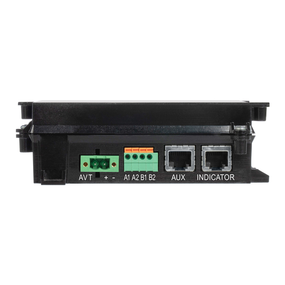
1P = Single-Phase / DC System B = Battery Powered Indicator 08 = 8’ (2 .4m) System Cable 16 = 16’ (4 .8m) System Cable NOTE: Accessories are available for the VS2-AVT, refer to www .panduit .com . POWER FOR AVT TEST Battery Auxiliary DC Power over Ethernet (PoE)* 3 .6V lithium... -
Page 5: Indicator Module
INDICATOR MODULE The 2 .0 AVT isolation module is compatible with up to two indicator modules . The test can be initiated at either location and results will be shown simultaneously on both indicators . Primary indicator must be installed locally near the isolation module . A combination of battery-powered and battery-free indicators can be used in either port . -
Page 6: Technical Specifications
(VFD) or other circuit elements generating high frequency energy (waveforms exhibiting high Electro-Magnetic Inter- ference (EMI)) . For more information on where to position the VeriSafe 2 .0 AVT in VFD applications, see the Technical Note available on Panduit .com . Environmental Ratings Operating Temperature -25°C to 60°C (-13°F to 140°F) -
Page 7: Avt Quiescent Current, Voltage Illumination Level
Quiescent Current Battery Powered Per Phase: 0 .85 mA rms @ 480 Vrms; 1 .2 mA rms @ 1000 Vrms Auxiliary (DC or PoE) Powered Per Phase: 0 .33mA rms @ 480 Vrms; 0 .65mA rms @ 1000 Vrms Voltage Presence Indicators (Red LEDs) - Voltage Illumination Level Voltage AC System Voltage DC System Voltage... -
Page 8: Dimensions
Dimensions UNITS = inches [mm] NOTES: BATTERY POWERED INDICATOR MODULE BATTERY FREE INDICATOR MODULE 2.38 0.21 PANEL KNOCKOUT (FOR INDICATOR MODULE INSTALLATION) INSTRUCTION LABEL 3.20 The Indicator Module is designed „ [81.3] for use with a standard 30 mm AFE 2.0 knockout with notch . -
Page 9: Schematics
Schematics WARNING: The AVT must be installed correctly and grounded as described in this Instruction Manual to provide proper indication of „ absence of voltage . Sensor leads must not be mechanically connected with each other for the device to verify connection to the circuit . - Page 10 Schematics (cont .) DC SYSTEMS DC SYSTEM: NEGATIVE GROUND DC SYSTEM: POSITIVE GROUND External Enclosure External Enclosure System System Ground Ground Bond Bond Green / Yellow Green / Yellow Isolation Module Isolation Module DC SYSTEM: 3 WIRE CENTER GROUND DC SYSTEM: ISOLATED GROUND External Enclosure External...
-
Page 11: Installation Considerations
Installation Considerations This section provides guidelines for installing the 2 .0 AVT . It also addresses common application scenarios and describes best practices . GENERAL INFORMATION Before installing the AVT, identify all sources of electrical energy in the equipment . Install the AVT at the point in the circuit where you would normally test for voltage . -
Page 12: Installation Instructions
Installation Instructions Special Hazardous Locations Conditions The equipment shall be installed in an enclosure that provides a degree of protection not less than IP 54 in accor- „ of Use dance with IEC 60079-0 . The enclosure must only be accessible with use of a tool . „... - Page 13 INDICATOR MODULE AND INSTRUCTION LABEL BATTERY POWERED INDICATOR MODULE Panel Nut 1. Tighten the panel nut until both it and the gasket make full contact with the enclosure Indicator surface . Then, tighten an additional 1/4 turn . Gasket Module 2.
-
Page 14: Commisioning Checklist
Commissioning Checklist: REPEAT THE COMMISSIONING CHECKLIST WHEN CHANGES TO THE ELECTRICAL SYSTEM ARE MADE. De-energize the circuit that is being monitored by the AVT . ‡ Visually inspect the AVT . ‡ AVT system cable: Verify cable is locked into place on both the indicator module and isolation module . „... -
Page 15: Operating Instructions
Operating Instructions WARNING: To avoid electric shock, always de-energize power before entering an electrical enclosure . „ Always follow safety and lockout/tagout procedures when working on or near electrical systems and equipment . „ Use proper personal protective equipment (PPE) when working around sources of hazardous electrical energy . „... -
Page 16: Troubleshooting
Network Module „ Verify the connections between the network module and isolation module are properly terminated . „ Should a problem occur during installation, operation or maintenance of the VeriSafe 2.0 AVT, contact Panduit Technical Support. VeriSafe 2.0 AVT June 2022... -
Page 17: Maintenance
„ crush, recharge, disassemble or heat above 85°C (185°F), incinerate, or expose contents to water . The AVT will not work with a standard alkaline 1 .5 V AA battery . Use only Panduit approved battery . „ Battery, system cable, o-rings and gaskets can be replaced . No other part of the product is serviceable . - Page 18 5 years . BATTERY FREE INDICATOR MODULE BATTERY POWERED INDICATOR MODULE For the battery free indicator module, order Panduit SKU For the battery powered indicator module, order Panduit SKU VS2-AVT-GASKET for gasket replacement kit .
-
Page 19: Warranty
Panduit warrants that the Panduit product, and each part or component of the Panduit product, will comply with Panduit’s published specifications and will be free from defects in material and workmanship for a period of 1 year from the date of invoice from Panduit or its authorized distributor, not to exceed 18 months from the original date of shipment from Panduit’s facility .
Need help?
Do you have a question about the VerySafe VS2-AVT Series and is the answer not in the manual?
Questions and answers