
Subscribe to Our Youtube Channel
Related Manuals for CyberPower PR750ELCDRT1U


Summary of Contents for CyberPower PR750ELCDRT1U
- Page 1 User’s Manual Professional Rack Mount LCD Series PR750ELCDRT1U/PR1000ELCDRT1U K01-0000098-00...
-
Page 2: Important Safety Instructions
DO NOT INSTALL THE UPS WHERE IT WOULD BE EXPOSED TO DIRECT SUNLIGHT OR NEAR A STRONG HEAT SOURCE! DO NOT BLOCK OFF VENTILATION OPENINGS AROUND THE HOUSING! DO NOT CONNECT DOMESTIC APPLIANCES SUCH AS HAIR DRYERS TO UPS OUTPUT SOCKETS. Copyright © 2009 CyberPower Systems, Inc. -
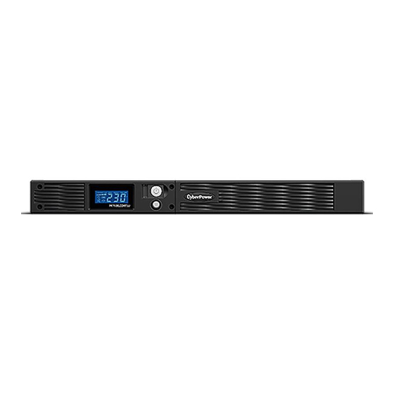
Page 3: Automatic Voltage Regulator(Avr)
Interface Cable (DB-9) x 1; (9) Power Cord x 4 AUTOMATIC VOLTAGE REGULATOR(AVR) The PR750ELCDRT1U/ PR1000ELCDRT1U can stabilise utility power inconsistances. The utility power may be damaging to important data and hardware, but Automatic Voltage Regulation helps the computer not experience dangerous voltage levels. -
Page 4: Basic Operation
Indicates that the AC utility input power’s condition is normal and that the UPS outlets are providing power, free of surges and spikes. 3. Power Switch Master on/off switch for equipment connected to the UPS. 4. LCD Readout Toggle Button Used to select among a variety of information the LCD can display. Copyright © 2009 CyberPower Systems, Inc. -
Page 5: Rear Panel Description
INSTRUCTIONS before servicing the batteries: Servicing the batteries should only be performed by professionals. For further information please contact your dealer, or email to: service@cyberpower-eu.com. Make a note for the replacement battery pack number, (RBP422), regarding PR750ELCDRT1U and PR1000ELCDRT1U models. - Page 6 BATTERY REPLACEMENT (continued) CAUTION! Use only the specified type of battery: HR9-6(BB) for PR750ELCDRT1U/ PR1000ELCDRT1U. Contact your dealer for replacement batteries. CAUTION! The battery may represent the risk of electrical shock. Do not dispose of batteries on fire, since they may explode. Follow all local ordinances regarding the proper disposal of batteries.
-
Page 7: Definitions For Illuminated Lcd Indicators
BATT. CAPACITY: BATT. CAPACITY is shown as a bar chart; each segment indicates approximately a 20% of battery capacity. LOAD CAPACITY: Load CAPACITY is shown as a bar chart; each segment indicates approximately a 20% of load capacity. Copyright © 2009 CyberPower Systems, Inc. - Page 8 Digital Value Display Select SW Load Battery Input Output % of % of Press Voltage Voltage Time Load Battery Initial (return) Press>4sec (sound disable) Press>4sec again(sound enable) overload “V” illuminated, “X” Not illuminated, “— “either Copyright © 2009 CyberPower Systems, Inc.
- Page 9 Delay Time: The time delay between switching from Battery Mode to Line Mode. There are 9 different settings. The default setting is 0 minutes. b. Battery Pack Numbers: PR750ELCDRT1U/ PR1000ELCDRT1U do not support this function, and the LCD always shows 0.
-
Page 10: Technical Specifications
Battery or AVR Mode. Under this condition GreenPower UPS and a traditional UPS would operate about the same. On average utility power operates 88% of the time and the CyberPower GreenPower Technology will work in its money/energy saving Bypass Mode. TECHNICAL SPECIFICATIONS Model...
Need help?
Do you have a question about the PR750ELCDRT1U and is the answer not in the manual?
Questions and answers