Table of Contents
Advertisement
Quick Links
Advertisement
Table of Contents

Subscribe to Our Youtube Channel
Related Manuals for Crystal Quest C-100

Summary of Contents for Crystal Quest C-100
- Page 1 C-100 Controller Installation Manual Copyright 2018 Crystal Quest ®...
-
Page 2: Table Of Contents
TABLE OF CONTENTS I . I n t rod u ct i on..................3 I I . -
Page 3: I N T Rod U Ct I On
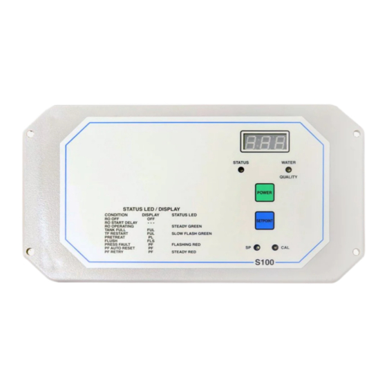
C-100 INTRODUCTION The Advantage Controls C-100 RO controller is a state of the art control system for commercial and industrial reverse osmosis systems. The C-100 is a microprocessor-controlled system that can monitor pressure and level switches. A TDS monitor/controller with adjustable limit is an integral part of the unit. The S100 displays system status and sensor and switch input status using a status LED and a 3-digit LED display. -
Page 4: I I . I N S T A L La T Ion
INSTALLATION Mounting Mount the S100 in a convenient location on the RO equipment using the integral mounting flanges. Power Wiring Before applying power to the unit, verify that the voltage jumpers are configured correctly for the voltage WARNING: that will power the unit. The voltage jumpers are located below the transformer. For 120 VAC operation, there should be a wire jumper installed between J1 and J3 and a second wire jumper installed between J2 and J4. -
Page 5: Switch Inputs
INSTALLATION Switch Inputs Switch inputs are connected to P2. The connections for these inputs are not polarity sensitive and can be connected to either terminal. The switch inputs should be dry contact closures only. WARNING: Applying voltage to these terminals will damage the controller. The switches can be either normally open or normally closed, but all switches must be the same. -
Page 6: I I I . F Ron T P A N E L De S C Ri P T I O N
INSTALLATION FRONT PANEL DESCRIPTION LED DISPLAY - Shows status of system and water quality. STATUS LED - Shows operating status of unit. WATER QUALITY LED - GREEN if OK, RED if above limit. POWER KEY - Places controller in operating or standby mode. SETPOINT KEY - Places display in mode to display current setpoint. -
Page 7: I V. S Y S T E M Op E Ra T Io N
SYSTEM OPERATION Operation The C-100 has 2 modes of operation, a standby mode and an operating mode. In the standby mode, the unit is effectively off. All outputs are turned off and the display shows OFF. In the operating mode, the unit operates automatically. All inputs are monitored and the outputs are controlled accordingly. Pressing the Power key will toggle the unit from standby to operate or from operate to standby. -
Page 8: P Fa Ut O R E S E T / P F R E Tr Y
SYSTEM OPERATION PF Auto Reset / PR Retry With J8 in the A position, the power must be cycled using the Power key to clear a pressure fault shut down. A PF auto reset function is enabled by placing J8 in the B position. When a pressure fault occurs with the PF auto reset enabled, the controller will automatically reset after a 60 minute delay and the controller will start. -
Page 9: Water Quality Display
SYSTEM OPERATION Water Quality Display The water quality display shows the current water quality when the controller is operating normally and status messages when the controller is shut down. The water quality display is 0-999 PPM. If the water quality is above 999, the display will show ^ ^ ^. If the water quality is below the setpoint, the water quality lamp will be green. -
Page 10: Wa R R A N T Y & G U R A N Te
WARRANTY & GURANTEE VOID ABILITY OF WARRANTY This Warranty shall be void and unenforceable as to any Seller product which has been damaged by accident, mishandling, abuse or has been repaired, modified, altered, disassembled or otherwise tampered with by anyone other than Seller or an authorized Seller service representative;...
Need help?
Do you have a question about the C-100 and is the answer not in the manual?
Questions and answers