
Subscribe to Our Youtube Channel
Related Manuals for 7starlake SCH-401


Summary of Contents for 7starlake SCH-401
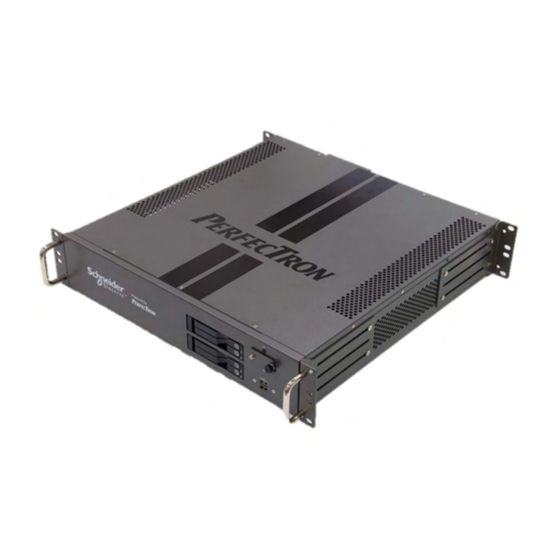
- Page 1 SCH-401 IEC-61850-3, IEEE-1613 Substation 2U Server User’s Manual Revision Date: June.9.2021...
- Page 2 SCH-401 User’s Manual Revision Date: June.9.2021 Safety Information Electrical safety To prevent electrical shock hazard, disconnect the power cable from the electrical outlet before relocating the system. When adding or removing devices to or from the system, ensure that the power cables for the devices are unplugged before the signal cables are connected.
- Page 3 First release Packing List Item Description Q’ty SCH-401 IEC-61850-3, IEEE-1613 Substation 2U Server Driver CD Ordering information SCH-401 IEC-61850-3, IEEE-1613 Substation 2U Server with Intel 10th Gen Xeon® W-1200 or Core™ i9/i7/i5 Processor, 2 × RJ45 GbE, 1 x IPMI, 67V~143V DC-IN,TPM/FTDI Support, 2 x 200W DC/DC Redundant Power Supply, Operating Temperature...
- Page 4 In order to meet the RoHS compliant directives, 7Starlake has established an engineering and manufacturing task force to implement the introduction of green products. The task force will ensure that we follow the standard 7Starlake development procedure and that all the new RoHS components and new manufacturing processes maintain the highest industry quality levels for which 7Starlake are renowned.
-
Page 5: Table Of Contents
SCH-401 User’s Manual Revision Date: June.9.2021 Chapter 1 : Production Introduction ....................... 5 1.1 Specifications ........................... 5 1.2 Front Panel I/O Placement ....................... 7 1.3 Rear Panel I/O Placement ......................8 1.4 Mechanical Dimensions ......................9 Chapter 2 : Rear I/O Ports ........................10 2.1 LAN/IPMI port ........................ -
Page 6: Chapter 1 : Production Introduction
SCH-401 User’s Manual Revision Date: June.9.2021 Chapter 1 : Production Introduction 1.1 Specifications System 10th Generation Intel® Xeon® W-1200 Processors Intel® Xeon® W-1290TE Processor (20M Cache, up to 4.50 GHz) Intel® Xeon® W-1250TE Processor (12M Cache, up to 3.80 GHz) 10th Generation Intel®... - Page 7 SCH-401 User’s Manual Revision Date: June.9.2021 FTDI OS support list Windows Windows 10 x64 Linux Ubuntu, Red Hat Mechanical and Evvironmental Dimension 430 x 450 x 88 mm ( W x D x H ) Operating Temp. -20°C to 60°C Storage Temp.
-
Page 8: Front Panel I/O Placement
SCH-401 User’s Manual Revision Date: June.9.2021 1.2 Front Panel I/O Placement 4 x HDD Tray 2 x USB2.0 Power Button... -
Page 9: Rear Panel I/O Placement
SCH-401 User’s Manual Revision Date: June.9.2021 1.3 Rear Panel I/O Placement IPMI 4 x USB3.2 2 x GbE DVI-D 2 x DP 4 x PCIe expansion 2 x DC-IN... -
Page 10: Mechanical Dimensions
SCH-401 User’s Manual Revision Date: June.9.2021 1.4 Mechanical Dimensions... -
Page 11: Chapter 2 : Rear I/O Ports
SCH-401 User’s Manual Revision Date: June.9.2021 Chapter 2 : Rear I/O Ports 2.1 LAN/IPMI port 2.2 VGA/DVI-D/DP port A VGA port and a DVI-D port are located next to DisplayPorts 1/2 on the I/O back panel. Use these connections for VGA and DVI displays. The VGA connector is on top and the DVI-D is on the bottom. -
Page 12: Chapter 3 : System Setup
SCH-401 User’s Manual Revision Date: June.9.2021 Chapter 3 : System Setup 3.1 Removing the Top Cover from the Chassis The sixteen screws on the top and side are used to secure the cover to the chassis. Remove these screws and put them in a safe place for later use 3.2 Installing PCIe Card... -
Page 13: Install The Screws On The Upper Cover
3.3 Install the screws on the upper cover Attach the screws at sixten locations to complete the installation 3.4 2.5” Easy Swap SSD installation SCH-401 support four 2.5” Easy Swap SSD Use Tri-angle security key to open keylock and pull out the 2.5”SSD tray. •... -
Page 14: Starting
SCH-401 User’s Manual Revision Date: June.9.2021 4.1 Starting To enter the setup screens, perform the following steps: • Turn on the computer and press the <Del> key immediately. • After the <Del> key is pressed, the main BIOS setup menu displays. Other setup screens can be accessed from the main BIOS setup menu, such as the Chipset and Power menus. - Page 15 SCH-401 User’s Manual Revision Date: June.9.2021 The Main BIOS setup screen has two main frames. The left frame displays all the options that can be configured. Grayed-out options cannot be configured; options in blue can. The right frame displays the key legend. Above the key legend is an area reserved for a text message. When an option is selected in the left frame, it is highlighted in white.
- Page 16 SCH-401 User’s Manual Revision Date: June.9.2021 17:30:00. BIOS Version This item displays the version of the BIOS ROM used in the system. Build Date This item displays the date when the version of the BIOS ROM used in the system was built.
-
Page 17: Advanced Setup Configuations
SCH-401 User’s Manual Revision Date: June.9.2021 4.4 Advanced Setup Configuations... - Page 18 SCH-401 User’s Manual Revision Date: June.9.2021...
- Page 19 SCH-401 User’s Manual Revision Date: June.9.2021...
- Page 20 SCH-401 User’s Manual Revision Date: June.9.2021...
- Page 21 SCH-401 User’s Manual Revision Date: June.9.2021...
- Page 22 SCH-401 User’s Manual Revision Date: June.9.2021...
- Page 23 SCH-401 User’s Manual Revision Date: June.9.2021...
- Page 24 SCH-401 User’s Manual Revision Date: June.9.2021...
- Page 25 SCH-401 User’s Manual Revision Date: June.9.2021...
- Page 26 SCH-401 User’s Manual Revision Date: June.9.2021...
- Page 27 SCH-401 User’s Manual Revision Date: June.9.2021...
- Page 28 SCH-401 User’s Manual Revision Date: June.9.2021...
- Page 29 SCH-401 User’s Manual Revision Date: June.9.2021...
- Page 30 SCH-401 User’s Manual Revision Date: June.9.2021...
- Page 31 SCH-401 User’s Manual Revision Date: June.9.2021...
- Page 32 SCH-401 User’s Manual Revision Date: June.9.2021...
- Page 33 SCH-401 User’s Manual Revision Date: June.9.2021...
- Page 34 SCH-401 User’s Manual Revision Date: June.9.2021...
- Page 35 SCH-401 User’s Manual Revision Date: June.9.2021...
- Page 36 SCH-401 User’s Manual Revision Date: June.9.2021...
- Page 37 SCH-401 User’s Manual Revision Date: June.9.2021...
- Page 38 SCH-401 User’s Manual Revision Date: June.9.2021...
- Page 39 SCH-401 User’s Manual Revision Date: June.9.2021...
- Page 40 SCH-401 User’s Manual Revision Date: June.9.2021...
- Page 41 SCH-401 User’s Manual Revision Date: June.9.2021...
- Page 42 SCH-401 User’s Manual Revision Date: June.9.2021...
- Page 43 SCH-401 User’s Manual Revision Date: June.9.2021...
- Page 44 SCH-401 User’s Manual Revision Date: June.9.2021...
- Page 45 SCH-401 User’s Manual Revision Date: June.9.2021...
- Page 46 SCH-401 User’s Manual Revision Date: June.9.2021...
- Page 47 SCH-401 User’s Manual Revision Date: June.9.2021...
- Page 48 SCH-401 User’s Manual Revision Date: June.9.2021...
- Page 49 SCH-401 User’s Manual Revision Date: June.9.2021...
- Page 50 SCH-401 User’s Manual Revision Date: June.9.2021...
-
Page 51: Event Logs
SCH-401 User’s Manual Revision Date: June.9.2021 4.5 Event Logs... - Page 52 SCH-401 User’s Manual Revision Date: June.9.2021...
-
Page 53: Ipmi
SCH-401 User’s Manual Revision Date: June.9.2021 4.6 IPMI... - Page 54 SCH-401 User’s Manual Revision Date: June.9.2021...
- Page 55 SCH-401 User’s Manual Revision Date: June.9.2021...
-
Page 56: Security
SCH-401 User’s Manual Revision Date: June.9.2021 4.7 Security... - Page 57 SCH-401 User’s Manual Revision Date: June.9.2021...
- Page 58 SCH-401 User’s Manual Revision Date: June.9.2021...
- Page 59 SCH-401 User’s Manual Revision Date: June.9.2021...
- Page 60 SCH-401 User’s Manual Revision Date: June.9.2021...
- Page 61 SCH-401 User’s Manual Revision Date: June.9.2021...
- Page 62 SCH-401 User’s Manual Revision Date: June.9.2021...
-
Page 63: Boot
SCH-401 User’s Manual Revision Date: June.9.2021 4.8 Boot... - Page 64 SCH-401 User’s Manual Revision Date: June.9.2021...
- Page 65 SCH-401 User’s Manual Revision Date: June.9.2021...
-
Page 66: Save & Exit
SCH-401 User’s Manual Revision Date: June.9.2021 4.9 Save & Exit... - Page 67 SCH-401 User’s Manual Revision Date: June.9.2021...
Need help?
Do you have a question about the SCH-401 and is the answer not in the manual?
Questions and answers