
Related Manuals for COMBA CriticalPoint QE Series

Summary of Contents for COMBA CriticalPoint QE Series
- Page 1 CriticalPoint Public Safety AMS ANTENNA MONITORING SYSTEM USER MANUAL Public Safety AMS SERIES QE: 1-0-0 FIRMWARE: V271 Comba Telecom Ltd.
- Page 2 The information contained herein is the responsibility of and is approved by the following, to whom all enquiries should be directed: This is an unpublished work the copyright in which vests in Comba International ("Comba"). All rights reserved. The information contained herein is confidential and the property of Comba and is supplied without liability for errors or omissions.
-
Page 3: Table Of Contents
ANTENNA MONITORING SYSTEM (AMS) USER MANUAL CONTENTS Section Page CONTENTS ............................3 INDEX TO FIGURES AND TABLES ..................... 5 HISTORY ............................6 GLOSSARY OF TERMS ......................... 7 SAFETY NOTICES AND ADMONISHMENTS ................8 GENERAL INFORMATION ......................9 EQUIPMENT DESCRIPTION ....................... 10 EQUIPMENT BOCK DIAGRAM .................... - Page 4 ANTENNA MONITORING SYSTEM (AMS) USER MANUAL 4.4.1 TAGS & ALARMS .......................... 33 4.4.2 TAG SCAN FAIL ..........................34 MAINTENANCE ..........................35 APPENDICES ..........................35 APPENDIX A: TOOLS ........................35 APPENDIX B: TAG LIST ....................... 36 APPENDIX C: ALARM LOG EXAMPLE ..................36 APPENDIX D: RMA (RETURN MATERIAL AUTHORIZATION) ..........
-
Page 5: Index To Figures And Tables
ANTENNA MONITORING SYSTEM (AMS) USER MANUAL INDEX TO FIGURES AND TABLES Figure 1: Front, Side and Bottom Views of the AMS Enclosure .................9 Figure 2: AMS System Block Diagram ......................10 Figure 3: AMS External Layout .........................18 Figure 4: AMS Internal Component Diagram ....................12 Figure 5: Mounting Rack Overview ........................10 Figure 6: AMS Connector Locations .........................18 Figure 7: Dry Contact NO-NC Example ......................21... -
Page 6: History
ANTENNA MONITORING SYSTEM (AMS) USER MANUAL HISTORY Change No. Details Of Change 1-0-0 This manual first created and issued in June 2022. ENU STATUS: 1-0-0 Copyright - refer to title page Page 6... -
Page 7: Glossary Of Terms
ANTENNA MONITORING SYSTEM (AMS) USER MANUAL GLOSSARY OF TERMS Abbreviation Definition Authority Having Jurisdiction Antenna Monitoring System Bi-Directional Amplifier Distributed Antenna System Decibel Decibels relative to 1 milliwatt Downlink Digital Integrated Module Electrostatic Discharge Frequency Selection Graphical User Interface Hertz Main Control Unit Megahertz Noise Figure... -
Page 8: Safety Notices And Admonishments
ANTENNA MONITORING SYSTEM (AMS) USER MANUAL SAFETY NOTICES AND ADMONISHMENTS This document contains safety notices in accordance with appropriate standards. In the interests of conformity with the territory standards for the country concerned, the equivalent territorial admonishments are also shown. Any installation, adjustment, maintenance, and repair of the equipment must only be carried out by trained, authorized personnel. -
Page 9: General Information
Failure alarming requirements. The system can also increase the efficiency and accuracy of monitoring a passive antenna system, as well as troubleshooting the passive network. Main Features Monitor In-building DAS status in real time for all passive components, antenna coax, and Comba service antennas Report overall status through dry contact alarming - login to identify alarms from individual antenna ... -
Page 10: Equipment Description
ANTENNA MONITORING SYSTEM (AMS) USER MANUAL 1 EQUIPMENT DESCRIPTION EQUIPMENT BOCK DIAGRAM The AMS uses a diplexer to pass the Public Safety downlink/uplink (VHF/UHF/700/800) frequencies and inject/extract the unlicensed 900MHz frequency to monitor the antenna RFID tags. The unlicensed 900MHz frequency (user definable in the GUI) is pulsed from the AMS throughout the passive DAS network/antenna arrays, the antennas tag information is then reflected to the AMS. -
Page 11: Equipment Layout
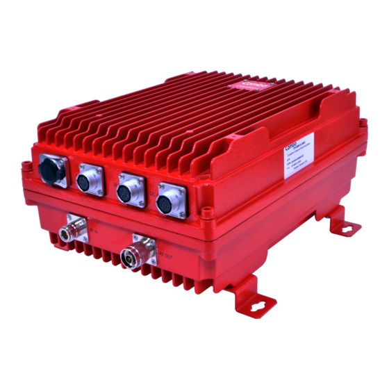
ANTENNA MONITORING SYSTEM (AMS) USER MANUAL EQUIPMENT LAYOUT Shown below is the external layout of the AMS unit. Ethernet Port – ALM2 – Tag ALM1 – AMS DC-48V IN WEB Login Malfunction Malfunction RF IN – N-Female RF OUT – N-Male From BDA To Service ANT. -
Page 12: Equipment Constitution
ANTENNA MONITORING SYSTEM (AMS) USER MANUAL EQUIPMENT CONSTITUTION The AMS unit consists of the following components: Main Control Unit (MCU): The MCU is used to monitor and control the operation of the AMS. Power Supply Unit (PSU): The PSU converts the input voltage into a stable DC supply to provide power for the internal modules. -
Page 13: Installation
ANTENNA MONITORING SYSTEM (AMS) USER MANUAL 2 INSTALLATION WARNINGS AND ALERTS RF Emissions & RF Exposure There may be situations, particularly for workplace environments near high-powered RF sources, where recommended limits for safe exposure of human beings to RF energy could be exceeded. In such cases, restrictive measures or actions may be necessary to ensure the safe use of RF energy. -
Page 14: Site Planning Considerations
ANTENNA MONITORING SYSTEM (AMS) USER MANUAL SITE PLANNING CONSIDERATIONS 2.2.1 SITE PLANNING Site Considerations Outdoor equipment is designed to be waterproof, rainproof, and with snow protection. Temporary protection should be taken when the equipment enclosure is opened for installation or maintenance in an outdoor environment. -
Page 15: Installation Checklist
Service antennas should be selected based on the type of service area, e.g., indoor antenna for indoor application, and panel antenna for outdoor application. Additionally, DAS service antennas must be coordinated with Comba prior to installation, as RFID chips are required to be installed at the Comba factory ENU STATUS: 1-0-0... -
Page 16: Installation Procedures
Open and check each package against the packing list. If any items are missing, contact Comba ... -
Page 17: Wall Mounting
2.3.5 DRIP-LOOP Comba recommends that every horizontal cable entry to the equipment forms a 'U' before its entry to the equipment. Water on the cable will drip down at the bottom of the loop and will not accumulate at the equipment connectors. -
Page 18: Equipment Connectors
ANTENNA MONITORING SYSTEM (AMS) USER MANUAL EQUIPMENT CONNECTORS 2.4.1 AMS CONNECTORS The AMS is designed for all cable entries from the right or the left of the enclosure, as shown below. Figure 6: AMS Connector Locations Table 1: Equipment Connectors Identifier Descriptions RJ45 Connector for Ethernet connection (e.g., Remote Login) -
Page 19: Grounding Connection
RF cable connection is as follows: AMS RF OUT port Connects to the feeder cable from service antennas. AMS RF IN port Connects to the feeder cable from BDA downlink (Comba BDA MT port) 2.4.5 ETHERNET CONNECTION Establish an Ethernet connection using the ‘LAN’... -
Page 20: Dry Contact Cable Connection
ANTENNA MONITORING SYSTEM (AMS) USER MANUAL 2.4.6 DRY CONTACT CABLE CONNECTION Below are the pin definitions of the dry contact cables. Table 3: Pin Definition of Dry Contact Cables Pin NO. Description Color Code ALM1 CLOSE1 Red (Brown) COM1 AMS Failure/Power Loss Blue OPEN1 Yellow... -
Page 21: Dry Contact Alarms
ANTENNA MONITORING SYSTEM (AMS) USER MANUAL 2.4.7 DRY CONTACT ALARMS Port ALM1: Alarm 1 is fixed for AMS Failure. When the AMS loses power, this alarm is triggered RED (Brown)-CLOSE, YELLOW-OPEN, BLUE-COM Port ALM2: Alarm 2 is fixed for Antenna RFID Tag Missing. When an antenna RFID tag shows consecutively missing, this alarm is triggered RED (Brown)-CLOSE, YELLOW-OPEN, BLUE-COM Main Power Normal/Lost dry contact status:... -
Page 22: Ams Omt Gui Overview
ANTENNA MONITORING SYSTEM (AMS) USER MANUAL 3 AMS OMT GUI OVERVIEW The AMS can be monitored and controlled via the AMS OMT GUI; use the following guide to finish system parameter setting and commissioning. AMS OMT GUI CONNECTION Step 1: Connect the ETH port from the AMS to your PC RJ45 port with the regular RJ45 cable to set up a physical connection. -
Page 23: Omt Gui Introduction
ANTENNA MONITORING SYSTEM (AMS) USER MANUAL OMT GUI INTRODUCTION After connecting, the GUI will un-gray a select group of options, pending if the AMS is in Auto or Manual mode. By default, the AMS is in Manual mode during first startup. ... -
Page 24: Current Alarm]
ANTENNA MONITORING SYSTEM (AMS) USER MANUAL 3.2.1 [CURRENT ALARM] When selecting the [Current Alarm] Tab, the screen will show the equipment status consisting of: AMS malfunction alarm, Tag detection alert, and Tag malfunction alarm. AMS malfunction alarm – If AMS losses power, this is triggered on ALM 1. ... -
Page 25: Tag Manager]
ANTENNA MONITORING SYSTEM (AMS) USER MANUAL 3.2.2 [TAG MANAGER] When selecting the [Tag Manager] Tab, the screen will show tags currently registered on the AMS. Tags can be manually added, removed, or modified on this screen. Click to refresh list, add, delete, or export list List of tags AMS is scanning for... -
Page 26: Status]
ANTENNA MONITORING SYSTEM (AMS) USER MANUAL 3.2.3 [STATUS] When selecting the [Status] Tab, the screen will show the status of each tag. If the tag is “green”, there are no issues. If the tag is “red”, the AMS is not receiving information from the tag. ... -
Page 27: Alarm Log]
ANTENNA MONITORING SYSTEM (AMS) USER MANUAL 3.2.4 [ALARM LOG] When selecting the [Alarm Log] Tab, the screen will show all alarms logged during auto and manual mode. Refresh – Checks alarms from tags while operating in manual mode. Clear –... -
Page 28: Tag Scan]
ANTENNA MONITORING SYSTEM (AMS) USER MANUAL 3.2.5 [TAG SCAN] When selecting the [Tag Scan] Tab, this screen is used to automatically scan and add tags that the AMS can read on the passive DAS to the [Tag Manager]. Read – Starts the auto scan of tags the AMS can read. Automatically adds tags to [Tag Manager] once scan is finished. -
Page 29: Commissioning
ANTENNA MONITORING SYSTEM (AMS) USER MANUAL 4 COMMISSIONING PRE-COMMISSIONING TASKS After AMS installation, perform the following steps BEFORE POWERING UP and COMMISSIONING the equipment: Verify that the expected voltage, current and power levels do not violate any ratings. Visually inspect the power connection within the equipment. Ensure that the power cable is correctly and ... -
Page 30: Commissioning The Ams Equipment
ANTENNA MONITORING SYSTEM (AMS) USER MANUAL COMMISSIONING THE AMS EQUIPMENT To complete the installation and commissioning, users need to follow the below steps and wait 45 seconds between actions: Step 1: Click “Sync” to adjust the time of the AMS to match the computer’s time. Figure 16: Commissioning Procedure –... - Page 31 ANTENNA MONITORING SYSTEM (AMS) USER MANUAL Step 2: Scan the cable connected to the RF Out port on the AMS with a spectrum analyzer. Look for any traffic or noise between 900 to 935 MHz. If these is no noise or traffic on 910 MHz, keep “Frequency” at 910 under “Common Info”.
- Page 32 ANTENNA MONITORING SYSTEM (AMS) USER MANUAL 180 or 300 seconds with 3 or 2 cycles respectively, is generally acceptable for AHJ inspections. If there are no false alarms at the default settings, this is most recommended for testing and post inspection.
-
Page 33: Troubleshooting Tips
String interrupted Figure 19: Example Tag Table 9. Click [Tag Manager]. 10. Delete malfunctioning tag. 11. Power cycle AMS. 12. Call Comba Support for repair or replacement of faulty antenna. ENU STATUS: 1-0-0 Copyright - refer to title page Page 33... -
Page 34: Tag Scan Fail
ANTENNA MONITORING SYSTEM (AMS) USER MANUAL 4.4.2 TAG SCAN FAIL Tag Scan Fail If the Tag Scan is unable to see tags after ensuring all cables are connected and RL is within specifications, reduce power by 3 dB from 35 dBm until AMS is able to scan for all antennas. ... -
Page 35: Maintenance
ANTENNA MONITORING SYSTEM (AMS) USER MANUAL 5 MAINTENANCE The AMS is designed for trouble-free operation and generally does not need maintenance. Maintenance activities should only be carried out by trained personnel. Periodic inspection of the AMS is recommended, the recommended tasks include: Manually run tag check through the [Status] screen. -
Page 36: Appendix B: Tag List
ANTENNA MONITORING SYSTEM (AMS) USER MANUAL APPENDIX B: TAG LIST .CVS EXAMPLE APPENDIX C: ALARM LOG .CVS EXAMPLE ENU STATUS: 1-0-0 Copyright - refer to title page Page 36... -
Page 37: Appendix D: Rma (Return Material Authorization)
ANTENNA MONITORING SYSTEM (AMS) USER MANUAL APPENDIX D: RMA (RETURN MATERIAL AUTHORIZATION) End of Section End of Document ENU STATUS: 1-0-0 Copyright - refer to title page Page 37... - Page 38 ANTENNA MONITORING SYSTEM (AMS) USER MANUAL ENU STATUS: 1-0-0 Copyright - refer to title page Page 38...
Need help?
Do you have a question about the CriticalPoint QE Series and is the answer not in the manual?
Questions and answers