Table of Contents
Advertisement
Quick Links
Advertisement
Table of Contents

Related Manuals for COMBA CRITICALPOINT CP-AMS

Summary of Contents for COMBA CRITICALPOINT CP-AMS
- Page 1 CRITICALPOINT ANTENNA MONITORING SYSTEM USER MANUAL QE: 1-0-1...
- Page 2 The information contained herein is the responsibility of and is approved by the following, to whom all enquiries should be directed: This is an unpublished work the copyright in which vests in Comba International ("Comba"). All rights reserved. The information contained herein is confidential and the property of Comba and is supplied without liability for errors or omissions.
-
Page 3: Table Of Contents
INSTALLATION GUIDE FOR RX-7W22 CONTENTS Section Page CONTENTS ............................3 INDEX TO FIGURES AND TABLES ..................... 4 HISTORY ............................5 GLOSSARY OF TERMS ......................... 6 SAFETY NOTICES AND ADMONISHMENTS ................7 GENERAL INFORMATION ......................8 EQUIPMENT DESCRIPTION ......................9 MCU (MAIN CONTROL UNIT) BLOCK DIAGRAM ..............9 INSTALLATION .......................... -
Page 4: Index To Figures And Tables
INSTALLATION GUIDE FOR RX-7W22 INDEX TO FIGURES AND TABLES Figure 1: CriticalPoint Antenna Monitoring Solution System Block Diagram ............8 Figure 2: MCU (Main Control Unit) Block Diagram .....................9 Figure 3: Equipment Connectors ........................11 Figure 4: Tag Management ..........................14 Figure 5: Tag Status ............................ -
Page 5: History
INSTALLATION GUIDE FOR RX-7W22 HISTORY Change No. Details Of Change 1-0-0 This manual first created and issued in APR 2019 1-0-1 Change the Warning section 1-0-2 Change some descriptions ENU STATUS : 1-0-2 Copyright - refer to title page Page 5... -
Page 6: Glossary Of Terms
INSTALLATION GUIDE FOR RX-7W22 GLOSSARY OF TERMS Abbreviation Definition Automatic Level Control Attenuator Base Transceiver Station Channel Cross Sectional Area Decibel Decibels relative to 1 milliwatt Downlink Donor Terminal Duplexer Frequency Selection Hertz Identification Intermediate Frequency Low Noise Amplifier Line-of-Sight Main Control Unit Megahertz Mobile Terminal... -
Page 7: Safety Notices And Admonishments
INSTALLATION GUIDE FOR RX-7W22 SAFETY NOTICES AND ADMONISHMENTS This document contains safety notices in accordance with appropriate standards. In the interests of conformity with the territory standards for the country concerned, the equivalent territorial admonishments are also shown. Any installation, adjustment, maintenance and repair of the equipment must only be carried out by trained, authorized personnel. -
Page 8: General Information
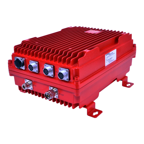
INSTALLATION GUIDE FOR RX-7W22 1 GENERAL INFORMATION The CriticalPoint Antenna Monitoring System consists of the Main Control Unit (MCU) and monitoring tags which are easily installed on the service antennas. The system utilizes RFID (Radio Frequency Identification) technology, that is incorporated into the DAS (Distributed Antenna System), to monitor the link status of the entire passive network. -
Page 9: Equipment Description
INSTALLATION GUIDE FOR RX-7W22 2 EQUIPMENT DESCRIPTION MCU (MAIN CONTROL UNIT) BLOCK DIAGRAM Figure 2: MCU (Main Control Unit) Block Diagram MCU generates a pilot signal at 910MHz or 915MHz, combines the RF signal from BDA/Signal Booster through the combiner and transmit the combined signal to each of the antenna, the RFID tags in the antenna will be energized by the pilot signal and send a response back to the MCU. -
Page 10: Installation
INSTALLATION GUIDE FOR RX-7W22 3 INSTALLATION WARNINGS AND ALERTS Radio Frequency Energies There may be situations, particularly for workplace environments near high-powered RF sources, where recommended limits for safe exposure of human beings to RF energy could be exceeded. In such cases, restrictive measures or actions may be necessary to ensure the safe use of RF energy. -
Page 11: Equipment Connection
INSTALLATION GUIDE FOR RX-7W22 EQUIPMENT CONNECTION 3.2.1 EQUIPMENT CONNECTORS Figure 3: Equipment Connectors Table 1: Equipment Connectors Identifier Descriptions DC48V Power cable connector for a pre-installed power cord for connection to DC (48V) RF IN N Female, connect to BDA or Signal Booster MT or Service port RF OUT N Female, connect to the passive system to the antennas RJ45 Connector for local WEB GUI connection. -
Page 12: Rf Cable Connection
INSTALLATION GUIDE FOR RX-7W22 3.2.2 RF CABLE CONNECTION AMS RF cables connection is as follows: ⚫ RF IN port → connect to BDA or Signal Booster’ MT or Service port ⚫ PF OUT port → connect to the passive system to the antennas 3.2.3 POWER CONNECTION Connect the power cord to the DC48V power source ⚫... -
Page 13: Tag Installation
INSTALLATION GUIDE FOR RX-7W22 4 TAG INSTALLATION Use addressable antenna: ⚫ IXD-360H04YJN-ADR: Low profile, Ceiling Mount, 380-2700MHz, H Pol, 360°, 2.0/2.2/4.5dBi ⚫ IXD-360H04MJN-ADR: Low profile, Ceiling Mount, 698-2700MHz, H Pol, 360°, 2.2/3.5/4.5dBi Or put the RFID tags on the antenna emission surface: ⚫... -
Page 14: Web Gui
INSTALLATION GUIDE FOR RX-7W22 5 WEB GUI The AMS can be monitored and controlled via the WEB GUI; use the following guide to finish system parameter setting and commissioning. WEB GUI CONNECTION Step 1: Connect the ETH port to the PC RJ45 port to set up a physical connection. Step 2: Manually change the IP address of the PC to be 192.168.1.100/255.255.255.0 Step 3: Open a browser (Chrome or Firefox), connect 127.0.0.1:8080/web_Antenna for login WEB GUI INTRODUCTION... -
Page 15: Tag Status]
INSTALLATION GUIDE FOR RX-7W22 5.2.2 [TAG STATUS] Figure 5: Tag Status • Display tag status the refresh ratio is based on the setting in “Query Cycle” in the “Device Parameter” page • readData will manually trigger a scan all the tags, can be used during set up ENU STATUS : 1-0-2 Copyright - refer to title page Page 15... -
Page 16: Alarm Log]
INSTALLATION GUIDE FOR RX-7W22 5.2.3 [ALARM LOG] Figure 6: Current Alarm Check the alarm log ENU STATUS : 1-0-2 Copyright - refer to title page Page 16... -
Page 17: Current Alarm]
INSTALLATION GUIDE FOR RX-7W22 5.2.4 [CURRENT ALARM] Figure 7: Current Alarm Current Alarm displays current Dry Contact Alarm 1 and Alarm 2 status ENU STATUS : 1-0-2 Copyright - refer to title page Page 17... -
Page 18: Device Info]
INSTALLATION GUIDE FOR RX-7W22 5.2.5 [DEVICE INFO] Figure 8: Device Info • DeviceNum: User can define the device information here such as a remark for the device • Serial Number: the serial number of the device • Date/Time: User can set the date and time ENU STATUS : 1-0-2 Copyright - refer to title page Page 18... -
Page 19: Device Parameters]
INSTALLATION GUIDE FOR RX-7W22 5.2.6 [DEVICE PARAMETERS] Figure 9: Device Info • Frequency: set the pilot signal frequency from 902-928MHz, default is 910MHz, user can change the frequency if there is interferences from 900MHz • OutputPower: Set the output power in dBm for the pilot signal, default is 30 (dBm) •... -
Page 20: Appendices
INSTALLATION GUIDE FOR RX-7W22 6 APPENDICES APPENDIX A: RMA (RETURN MATERIAL AUTHORIZATION) End of Section End of Document ENU STATUS : 1-0-2 Copyright - refer to title page Page 20... - Page 21 INSTALLATION GUIDE FOR RX-7W22 ENU STATUS : 1-0-2 Copyright - refer to title page Page 21...
Need help?
Do you have a question about the CRITICALPOINT CP-AMS and is the answer not in the manual?
Questions and answers