GOAL ZERO Yet Link Expansion Module Manual
- User manual (27 pages) ,
- User manual (8 pages) ,
- User manual (116 pages)
Advertisement
- 1 IMPORTANT SAFETY INSTRUCTIONS
- 2 GET TO KNOW YOUR GEAR
- 3 HOW TO INSTALL
- 4 HOW IT WORKS WITH HOME ENERGY STORAGE - TANK MODE
- 5 IMPORTANT SAFETY INSTRUCTIONS
- 6 HOW IT WORKS - VEHICLE MODE
- 7 CHARGING INDICATOR LIGHT
-
8
FREQUENTLY ASKED QUESTIONS
- 8.1 I'm charging my Yeti and it is connected to one or more Tank batteries, but my Tank batteries are not filling up. What should I do?
- 8.2 I installed my Link into my Yeti, connected my batteries, and I'm not showing a charge. What's going on?
- 8.3 Can I use third party, non-Goal Zero lead-acid batteries with the Link?
- 8.4 If I'm using my own third party lead acid batteries, how do I wire them up?
- 8.5 How many lead acid batteries can I plug into the Link?
- 8.6 Why is my Link only charging my Yeti up to 98%?
- 8.7 Once you put the Link into Vehicle mode, does it stay in Vehicle mode until you put it back into Tank Mode?
- 8.8 Would the solar still feed the Vehicle battery when the Vehicle is not running?
- 9 TECHNICAL SPECIFICATIONS
- 10 Videos
- 11 Documents / Resources
IMPORTANT SAFETY INSTRUCTIONS
Please save these instructions
Read all the instructions and cautions before beginning installation.
No liability is assumed for damages resulting in the use of the information contained herein.

The Goal Zero Yeti Link outputs very high amperages. Use only with Goal Zero cables. Altered cables or connectors or 3rd Party cables or connectors may be incompatible and may cause damage to components, vehicle or person.

To reduce risk of fire, injury to persons or damage to property, use only in the manner intended by Goal Zero Do NOT disassemble or attempt to repair the module.
Do NOT allow water to enter the module, the Goal Zero Yeti Lithium, or the Goal Zero Yeti Tank.
Ensure cable is fully inserted and tightly in place before use. Check upon subsequent uses. For questions, contact Solutions Center at support@goalzero.com or 1-888-794-6250
Do NOT chain third party solar panels or lead acid batteries in series (connecting positive to negative, positive to negative, etc.), as this can result in dangerously high levels of voltage that can cause serious damage to the Yeti Lithium and potential bodily injury.
Compatible with Yeti 1000, 1000X, 1400, 1500X, 3000, 3000X, and Yeti 6000X Lithium Power Stations
Never connect a power source to the Yeti Link before installing into the Yeti. Always connect the Link to the Yeti before connecting any power source.
Do not exceed 22V input for the Link. Doing so can cause serious damage to the Yeti and potential bodily injury. Take note of voltages when using third party solar panels or third party lead acid batteries with the module. Do not chain solar panels or lead acid batteries in series (positive to negative, positive to negative, etc.), as this can result in dangerously high voltages.
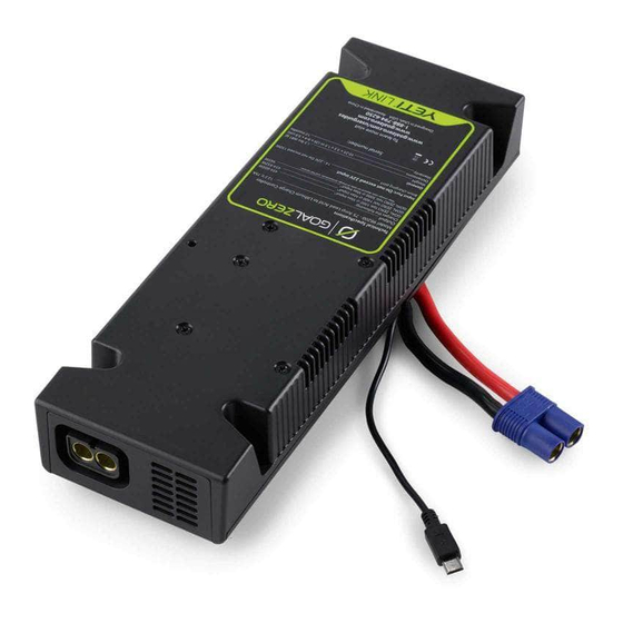
GET TO KNOW YOUR GEAR
Front of Link Expansion Module

Back of Link Expansion module

 Ensure cable is fully inserted and tightly in place before use. Check upon subsequent uses. For questions, contact Solutions Center at support@goalzero.com or 1-888-794-6250
HOW TO INSTALL
Tools you'll need: Phillips Screwdriver
- Turn off all the output ports and unplug the Yeti from any power source.

- Open the lid of the Yeti and remove the expansion module carriage from the Yeti by removing the six screws and sliding out the carriage.
- Insert the included Link Lock into the opening facing the back of the Yeti and line up the screw holes on the Link Lock with the holes on the Yeti.

- Take the blue connector and micro -USB cable on the Link module and insert them into the module and micro-USB ports on the Yeti, matching positive to positive, negative to negative, and micro to micro.


Do not exceed 22V input for the module. Doing so can cause serious damage to the Yeti and potential bodily injury. Take note of voltages when using third party solar panels with the module. Do not chain solar panels in series (positive to negative, positive to negative, etc.), as this can result in dangerously high voltages.

- Gently set the Link into place, tucking the cables into the opening.
- Using the provided four screws, secure the Link into place.
- Using the 8mm port, plug the power source into the Link.

Ensure cable is fully inserted and tightly in place before use. Check upon subsequent uses. For questions, contact Solutions Center at support@goalzero.com or 1-888-794-6250

- Proceed to plug in the EC8 cable and slide either the straight or the 90-degree EC8 cable holder over the cable and into the slots of the Link Lock. When the power source is correctly plugged in, the Input Charge Indicator light will turn blue. When the Tank is correctly connected to the Link and the power source is plugged in, the Lead-Acid State of Charge Indicator light will begin flashing green. NOTE: Upon plug-in, all LEDs will turn on, then off before correct lights are displayed. This may take up to 30 seconds.
- Power source will charge the Yeti first. When the Yeti is fully charged, power will begin to store in the Tank. NOTE: Power coming in from the 8mm port will flow through the Tank first and then into the Yeti. Without a Tank or third party battery attached, this port will not charge the Yeti directly.
Ensure cable is fully inserted and tightly in place before use. Check upon subsequent uses. For questions, contact Solutions Center at support@goalzero.com or 1-888-794-6250
HOW IT WORKS WITH HOME ENERGY STORAGE - TANK MODE
The Goal Zero Yeti Link Expansion Module integrates with a Goal Zero Yeti Lithium or Yeti X Portable Power Station and Goal Zero Yeti Tank Expansion Battery to increase your energy storage capacity. The Link is a Lithium Charge Controller that will draw up to 80A Max Current from a Lead-Acid power source.


- Once Link Module is installed into the Yeti you will be able to attach Goal Zero Yeti Expansion Tanks. To do this take the male EC8 cable from the Expansion Tank and plug it into the EC8 External Battery Connector on the Link Module that is installed in the Yeti Power Station.
- Then take either the included power supply or a Goal Zero Solar Panel (sold separately) and plug the 8mm barrel connector (blue ring) into the 8mm input port on the Link Module.
Note: Do not plug a tank into itself when multiple tanks are connected. - Power will flow into the battery and then into the Yeti power station. Once the power station is full the power will then start filling up the Tank.
NOTE:
- The 8mm port on the Link is the only way to charge both the Yeti and Tank. Input ports on the Yeti display will only charge the Yeti, not the Tank.
- When Link and Tank are properly installed, power passes through the 8mm port to the Tank and then into the Yeti. Thus, without a Tank or third party battery attached, you cannot charge the Yeti directly using the 8mm port on the Link.
Do not exceed 22V input for the module. Doing so can cause serious damage to the Yeti and potential bodily injury. Take note of voltages when using third party solar panels with the module. Do not chain solar panels in series (positive to negative, positive to negative, etc.), as this can result in dangerously high voltages.
IMPORTANT SAFETY INSTRUCTIONS
Please save these instructions
Read all the instructions and cautions before beginning installation.
Goal Zero recommends installation of the Yeti Link Vehicle Charging kit be installed by trained professional. Under no circumstance should the Goal Zero Yeti Link be installed with out the technical skills, technical information, tools and equipment required to properly complete the necessary procedures
Do NOT install a secondary battery in between the Battery and the Yeti Link Module Improper connections will damage the Yeti Link Module/Accessory cables and/or cause serious injury or death. Be sure that all wiring is connected to the appropriate polarity
Make sure cables are securely connected. Check cables periodically especially before and after uneven roadways
Confirm cables are installed correctly with no risk of pinching or abrasion. Pinching cables or any means of exposing internal cables can lead to malfunctions or fires
Keep live wires, terminals, and other bare parts away from contact with each other and other metal parts
Always wear eye protection when making battery connections
Always use rubber insulating grommet when drilling through steel panels to run the EC8 cable
Never route electrical cables across sharp edges
Never route electrical cables near parts that get hot
Never route electrical cables over battery terminals
Never route electrical cables through or near moving parts
Electrical cables should be safe from road spray, rain runoff, sand or gravel from road surface.
Goal Zero rejects any liability for problems and damage caused by the system being installed by untrained personnel.
The vehicle owner is responsible for the correct operation of the appliance
Keep away from sources of heat (e.g. too close to exhaust system components or directly behind the radiator, etc.).
To reduce risk of fire, injury to persons or damage to property, use only in the manner intended by Goal Zero
The Goal Zero Yeti Link Vehicle Charging Kit transmits, power into the Link Module and Yeti at very high amperages up to 80A Max Current. Use Extreme caution when installing. Use only Goal Zero supplied cables and connections in installation. If installed with 3rd party connections or alterations are made to Goal Zero suppled cables damage to components, vehicle or person may occur.
Improper connections will damage the Yeti Link Vehicle Charging kit and/or cause serious injury or death. Be sure that all wiring is connected to the appropriate polarity
Never connect a power source to the Yeti Link before installing into the Yeti. Always connect the Link to the Yeti before connecting any power source.
Do not exceed 22V input for the Link. Doing so can cause serious damage to the Yeti and potential bodily injury. Take note of voltages when using third party solar panels or third party lead acid batteries with the module. Do not chain solar panels or lead acid batteries in series (positive to negative, positive to negative, etc.), as this can result in dangerously high voltages.
HOW IT WORKS - VEHICLE MODE
Quickly and easily recharge a Yeti Lithium (1000 or higher) from your vehicle while on the move. Charge rates vary from 25A - 80A Max Current (300W - 750W) depending on Yeti Lithium size and capacity.

How it Works
When placed in "Vehicle Mode," the Yeti Link allows your Yeti Lithium to safely pull power from your vehicle's alternator while the vehicle is running and stop pulling power when the vehicle is off.
NOTE: Yeti Link must be in Vehicle Mode to utilize this feature or it will drain your vehicle's battery. All Links come standard set in "Tank Mode."
- Once Link is installed in Yeti, switch Link from Tank Mode to Vehicle Mode by pushing the pinhole reset button on top of the Link four times.
- Indicator lights will turn on and blink together when the Link is successfully placed in Vehicle Mode.
- To switch back to Tank Mode, press pinhole reset button on top of the Link four more times. Indicator lights will scroll from bottom to top individually when the Link is successfully placed in Tank Mode.
NOTE: Do NOT place back in Tank Mode while connected to your vehicle.


- Once Link is switched to Vehicle mode you will be able to connect to your vehicles +/-battery or alternator. By using the Goal Zero EC8 Extension Cable.
Note: only use authentic Goal Zero cables to do this.
DO NOT use more than one Extension Cable
DO NOT have a secondary battery in between the Link Module and the vehicle alternator or main battery
- Connect the Ring Terminal Cable to the positive and negative terminals on the either the main battery or the alternator.
- Improper connections will damage the Yeti Link Module/Accessory cables and/or cause serious injury or death. Be sure that all wiring is connected to the appropriate polarity
- Plug the Male end of the EC8 Ring Terminal cable into the Female end of the EC8 Extension cable.
- Plug male end of Extension Cable into the External EC8 port of the Link Module and slide either the straight or the 90-degree EC8 cable holder over the cable and into the slots of the Link Lock.
•Make sure cables are securely connected. Check cables periodically especially before and after uneven roadways.
Ensure that you only use Goal Zero products between your Link and Alternator. Any other cables or wiring is not supported or recommended as these cables need to be rated to carry a minimum of 80A Max Current
Ensure cable is fully inserted and tightly in place before use.
Check upon subsequent uses. For questions, contact Solutions Center at support@goalzero.com or 1-888-794-6250
CHARGING INDICATOR LIGHT
Input Charge Indicator:
FLASHING BLUE - Power source is correctly plugged into 8mm input and charging.
BLUE - Lead-Acid battery is full.
Lead Acid State of Charge Indicator:
1 LED LIGHT - Lead-Acid battery is 25% full or less
2 LED LIGHTS - Lead-Acid battery is 25% - 50% full
3 LED LIGHTS - Lead-Acid battery is 50% - 75% full
ALL LED LIGHTS - Lead-Acid battery is 75% full or more
Error LED
FLASHING RED - Yeti is in an over voltage condition or lead acid battery is in an under voltage condition. Disconnect all Tank Cables from Link and Yeti and please call our solar experts at 888-794-6250.
NOTE:
- The 8mm port on the Link is the only way to charge both the Yeti and Tank. Input ports on the Yeti display will only charge the Yeti, not the Tank.
- When Link and Tank are properly installed, power passes through the 8mm port to the Tank and then into the Yeti. Thus, without a Tank or third party battery attached, you cannot charge the Yeti directly using the 8mm port on the Link.
FREQUENTLY ASKED QUESTIONS
I'm charging my Yeti and it is connected to one or more Tank batteries, but my Tank batteries are not filling up. What should I do?
First, make sure you are using the input on your Link to charge your system. This input is the only way to charge both your Tank(s) and Yeti at the same time. If you are using the correct input and still having a problem, try resetting by reinstalling your Link.
I installed my Link into my Yeti, connected my batteries, and I'm not showing a charge. What's going on?
Upon initial installation, the Link needs time to identify which type of Yeti you own in order to maximize performance. It can take up to 30 seconds to start operating.
Can I use third party, non-Goal Zero lead-acid batteries with the Link?
Although not recommended yes, you can use any 12V SLA or AGM deep cycle lead acid battery with the Link. However, you will need a Goal Zero Male Link Chaining Cable to connect your batteries to the Link.
If I'm using my own third party lead acid batteries, how do I wire them up?
A: When connecting multiple 12V lead-acid batteries to your Link, be sure to connect the batteries in parallel. Parallel connections will increase your current rating, but the voltage will stay the same.
Connecting batteries in series will increase the voltage, causing damage to the unit and possible personal injury or death.
How many lead acid batteries can I plug into the Link?
You can attach as many 12V lead-acid batteries to your Link as you'd like.
Why is my Link only charging my Yeti up to 98%?
The Link will only charge a Newer generation Yeti Lithium to 98%. This protection is in place to protect and prolong the life of your battery. Second generation Yeti Lithium power stations equipped with the latest firmware updates can be charged to 100%.
Once you put the Link into Vehicle mode, does it stay in Vehicle mode until you put it back into Tank Mode?
The Yeti Link will stay in Vehicle mode until you manually change it back to Tank mode. If moving the unit from your vehicle to then chain it to the Tank batteries in your home, you will need to change the Link from Vehicle Mode to Tank Mode.
Would the solar still feed the Vehicle battery when the Vehicle is not running?
Yes, if you have a solar panel plugged directly into the 8mm port on the Yeti Link, the panel will be charging both the Yeti and your Vehicle battery when it isn't running.
TECHNICAL SPECIFICATIONS
| Yeti Link Expansion Module | |
| 80A Max Current from External Tanks/ Power Source to the Yeti's internal Lithium Battery | |
| Charges the following: | |
| GOAL ZERO Yeti 1000X @ Max Input | 454-605W |
| GOAL ZERO Yeti 1500X @ Max Input | 454-750W |
| GOAL ZERO Yeti 3000X @ Max Input | 750W |
| Ports: Do not exceed 22V Input | |
| 8mm Charging port | 14 - 22V, Do not exceed 100W or 7.5A |
| External Battery Connector | 80A Max Current 10.7 - 15V |
| General: | |
| Weight | 1.5 lbs (680 g) |
| Dimensions | 10.25 x 3.3 x 1.5 in (26 x 8.4 x 3.8 cm) |
| Operating Usage Temp | 32-104 F (0-40C) |
| Warranty | 12 months |
| Certs |  |

VideosGoal Zero- Yeti Link Expansion Module Installation video, Recharge a Yeti Lithium from your vehicle Car
Documents / ResourcesDownload manual
Here you can download full pdf version of manual, it may contain additional safety instructions, warranty information, FCC rules, etc.
Advertisement


Need help?
Do you have a question about the Yeti Link and is the answer not in the manual?
Questions and answers