
Related Manuals for Telect 009-8005-3404H

Summary of Contents for Telect 009-8005-3404H
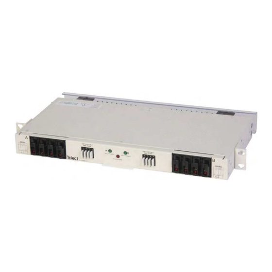
- Page 1 Dual 150A 4/4 TPA/GMT Fuse Alarm Panel Power :: 009-8005-3404H :: 009-8005-3404HRC User Manual Applies to : 009-8005-3404H and 009-8005-3404HRC © Telect, Inc., All Rights Reserved, 143252-1 A0 1.509.926.6000 :: telect.com...
-
Page 2: Table Of Contents
1.6 Accessories ........................10 1.7 Schematic Drawing ....................... 11 1.8 Assembly Drawing ......................12 List of Figures Figure 1 - Model 009-8005-3404H / HRC ................1 Figure 2 - Bracket Orientation ....................4 Figure 3 - Rack Mounting ......................4 Figure 4 - Ground Lug Connection..................5 Figure 5 - Input Lugs ......................5... -
Page 3: Overview
Please report any defective or missing parts to Telect at support@telect.com or call 1.509.926.6000. Telect is not liable for transit damage. If the product is damaged, please report it to the carrier and contact Telect. -
Page 4: Specifi Cations
GND Wire Size #10 AWG to #4 AWG Alarms Alarm Relay Contacts 2A @ 24Vdc 0.6A @ 48Vdc 1A @ 120Vac Max. Alarm Power Rating @48V: 130 mA (6.2 W) © Telect, Inc., All Rights Reserved, 143252-1 A0 1.509.926.6000 :: telect.com... - Page 5 -5˚C (23˚F) to 55˚C (131˚F) Humidity 0% to 90% and non-condensing Note: Wire sizes are recommended based on generally available lug sizes. Ensure wires sizes meet amperage requirements per NEC. © Telect, Inc., All Rights Reserved, 143252-1 A0 1.509.926.6000 :: telect.com...
-
Page 6: Installation Procedure
Panel brackets provide either fl ush or extended EIA or WECO mounting in a 19" or 23" rack. (See telect.com to order ETSI brackets.) The panel is confi gured at the factory for fl ush mounting in a 19" rack. -
Page 7: Figure 4 - Ground Lug Connection
13. Clean the terminals and lugs with a non-abrasive, non-metallic pad. 14. Telect recommends a light coating of anti-oxidant on the lugs and input BATT and RTN terminals before connecting the input terminals on the back of the panel, as shown in Figure 5. -
Page 8: Figure 6 - Disengaging A Tpa Fuse Holder
• Expect an open circuit (00Ω) between Terminals C and NO. 22. Make sure none of the fuse positions are engaged or contain operable fuses. Figure 8 - Alarm Terminals © Telect, Inc., All Rights Reserved, 143252-1 A0 1.509.926.6000 :: telect.com... -
Page 9: Figure 9 - Output Lug Connections
25. Remove the panhead screw on the terminal block. 26. Telect recommends a light coating of anti-oxidant on lugs and output BATT and RTN terminals before connecting lugs to terminals, as shown in Figure 9. (NEC specifi es only one lug and load at each output terminal.) -
Page 10: Figure 11 - Installing Gmt Fuses
34. Record the TPA and GMT output destinations on designation labels on the front panel. 35. Turn on equipment loads one at a time to verify proper operation of loads. Figure 12 - Installing Alarm Wiring © Telect, Inc., All Rights Reserved, 143252-1 A0 1.509.926.6000 :: telect.com... -
Page 11: Compression Lugs
T & B KN8-8R-D Telect assumes no liability from the application or use of these products. Neither does Telect convey any license under its patent rights or the patent rights of others. This document and the products described herein are subject to change without notice. -
Page 12: Accessories
Dual 150A 4/4 TPA/GMT Fuse Alarm Panel Power :: 009-8005-3404H 1.6 Accessories The following lists optional and replacement items for the panel. For compression lugs, please refer to Wire Sizing &, Label Convention Chart (Telect Part No. 117995) included with your panel Item Description Part Number... -
Page 13: Schematic Drawing
PWR A FUSE ALARM ALARM CONNECTION PWR B FUSE ALARM GMT OUTPUT TPA OUTPUT GMT OUTPUT BATT B TPA OUTPUT BATT B TPA FUSE HOLDER LEDS INPUT B BATT © Telect, Inc., All Rights Reserved, 143252-1 A0 1.509.926.6000 :: telect.com... -
Page 14: Assembly Drawing
.313 [0.79] #8 screw .10 [0.25] 1.01 [2.57] 10.20 [25.89] 8.38 [21.28 4.00 [10.16] .44 [1.10] 23.00 [58.42] 22.31 [56.67] 19.0 [48.3] 18.31 [46.51] 17.25 [43.82] 1.00 [2.54] 1.72 [4.37] © Telect, Inc., All Rights Reserved, 143252-1 A0 1.509.926.6000 :: telect.com...
Need help?
Do you have a question about the 009-8005-3404H and is the answer not in the manual?
Questions and answers