Table of Contents
Advertisement
Quick Links
Advertisement
Table of Contents

Subscribe to Our Youtube Channel
Related Manuals for Maytel HELMET CLIP INTERCOM

Summary of Contents for Maytel HELMET CLIP INTERCOM
- Page 1 User Manual Copyright ⓒ 2021. Lab-T, Inc.
- Page 2 USER'S MANUAL FOR HELMET CLIP INTERCOM Ver.10503MJB Perfect wireless Intercom solution for Helmet-wearing workers Maytel Co., Ltd.
-
Page 3: Table Of Contents
TABLE OF CONTENTES 1. General Information 1.1 Introduction 1.2 Main Feature 1.3 Package Components 1.4 Optional Accessories 2. Controls and Indicators 4, 5 3. Accessories and How to Install 4. RM Mode 7, 8 4.1 Operation Mode 5. S9 Mode 9, 10 5.1 Operation Mode 6. -
Page 4: Optional Accessories
1. General Information 1.1 Introduction "HELMET CLIP INTERCOM" is the most advanced and compact hands-free wireless intercom device that can be equipped to the helmet, which frees the users' hands and provides reliable full-duplex communication allowing up to 10 users to speak simultaneously. -
Page 5: Controls And Indicators
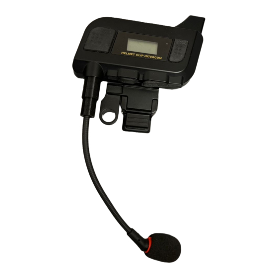
2. Controls and Indicators Down Button Power Button Up Button TALK Button Antenna MODE Button Belt Clip USB Jack Headset Jack MIC Jack HC-2.4G User’s Manual page 4... - Page 6 Power Button Press and hold the Power button for a second to turn the device power On/O MODE Button Select Channel number, ID number, Side Tone On/O , Microphone sensitivity level, and Wireless alarm Up Button Increase Volume level, Channel number, and ID number etc. in each mode Down Button Decrease Volume level, Channel number, and ID number etc.
-
Page 7: Accessories And How To Install
3. Accessories and How to Install How to install Belt Clip How to install Boom Microphone 1. Plug in the Boom Microphone to the MIC jack of HELMET CLIP INTERCOM. At this time, the connector and the groove of the plug must be properly tted. -
Page 8: Rm Mode
4. RM Mode RM operates as Main Master, Sub Master, and Slave depending on the ID setting of the device. Main Master sends beacon signals for group communication as shown in the Figure 1. Sub Master receives the beacon signal from the Main Master and sends it back to Subgroup S. -
Page 9: Operation Mode
Slave devices automatically switch between Subgroup M and Subgroup S to synchronize and send/receive voices. As shown in the Figure 1, the voice relaying of the Main Master and Sub Master can expand the coverage distance of wireless communication. 4.1 Operation Mode 1. -
Page 10: S9 Mode
5. S9 Mode S9 operates as Main Master, Sub Master, and Slave depending on the ID setting of the device. Main Master sends beacon signals for group communication as shown in the Figure 2, and the Slaves operate in synchronization with beacon signals. -
Page 11: Operation Mode
5.1 Operation Mode 1. ID of the device is assigned from 0~8, 9(Listen Only). 2. ID M works as the Main Master as shown in Table 2. Must be only one in the group. 3. The rest of the IDs work as Slaves. Devices with IDs 0~7 are xed. Each should be only one in the group. -
Page 12: How To Use
6. How to Use 6.1 Functions There are 2 modes in operation mode, NORMAL mode and SETTING mode. The default mode is NORMAL when turn on the power. Short press the MODE button to view each setting value in NORMAL mode. -
Page 13: Power On/O
6.2 Power On/O Press and hold the "Power" button for a second to turn the device power on/o . 6.3 Volume Adjustment Volume adjustment function to let the user to change the volume when needed. Volume Level appears on the top of the LCD screen when turn on the power. -
Page 14: Id Selection
Channel can be set from 0~39 . Long press the MODE button to nish the setting. 6.5 ID Selection ID setting function to let the user to change ID when needed. Turn on the power of the device. Long press the MODE button to go to SETTING mode. Short press MODE button to go to ID Setting screen. -
Page 15: Side Tone Selection
Long press the MODE button to nish the setting. 6.6 Side Tone Selection Side Tone can be turned On/O Turn on the power of the device. Long press the MODE button to go to SETTING mode. Short press MODE button 2 times to go to Side Tone Setting screen. The user can turn Side Tone On(SO) or O (SF) by Up/Down buttons. -
Page 16: Security Code Selection
Long press the MODE button to nish the setting. 6.8 Security Code Selection Security Code can be modi ed by the user. Turn on the power of the device. Long press the MODE button to go to SETTING mode. Short press MODE button 4 times to go to MIC level setting screen. The user can change the Security Code by Up/Down buttons. -
Page 17: Roaming Setting
Roaming Setting Roaming function can be set by the user. It can be set as Auto Roaming, Manual Roaming, Master Fix, Sub master Fix. Roaming function Description Auto Roaming Manual Roaming. Short press Power button to manually change connection between Master and Sub master Master Fix Sub master Fix... -
Page 18: Vox Selection
6.11 VOX Selection VOX can be set with this function. VOX function operates on devices with ID 0 ~ ID 8 Turn on the power of the device. Long press the MODE button to go to SETTING mode. Short press MODE button 9 times to go to Operation mode selection screen. -
Page 19: Magnetic Charging Connector Remover
7. Magnetic Charging Connector Remover Put the remover into the gap between the magnetic charging connector and the device. Move the remover for about 5 times with slight force, then the connector will be plugged out of the device. * Beware; The remover might be broken when too much force is applied. HC-2.4G User’s Manual page 18... -
Page 20: Speci Cation
8. Speci cation Dimension 100 x 69 x 32 mm Weight Frequency Range ISM 902.5MHz ~ 927 MHz Radio Interface GFSK Modulation Voice Codec 16bit/8KHz Tx Max Output Power TBD mW Rx Sensitivity -95dBm Environmental Rating IP54 Power Supply Li-ion Battery @3.7V/ 1,100 mA Antenna Internal Distance Range(LOS) -
Page 21: Declaration Of Conformity
9. Warranty Maytel will give 12 months warranty against failure made by the manufacturer from the date of purchase. The warranty will not cover damage made by the user, the user opening the equipment, moist, dirt, heat or cold. The warranty will not cover lightning/overvoltage. - Page 22 CAUTION Users are recommended to wear this device only on a helmet, and to reduce communication interface, it is recommended that the front face be seperated by at least 10mm.
- Page 23 This product has been certified with the following antennas, and may only be used with the same or less antenna gain. Antenna Max. Gain 3.83 dBi Helical Antenna This equipment complies with the essential requirements of EC Directive 2014/35/EU, 2014/30/EC and 2014/53/EU, as applicable.
Need help?
Do you have a question about the HELMET CLIP INTERCOM and is the answer not in the manual?
Questions and answers