Table of Contents
Advertisement
Quick Links
Advertisement
Table of Contents

Related Manuals for Hydraulic Projects PC45


Summary of Contents for Hydraulic Projects PC45
- Page 1 Hydraulic Projects Ltd PC45 Constant Running Marine Autopilot Hydraulic Pump Installation and Service Instructions Serial Number Engineering Excellence” “ FORM_PC45 ISS.4 Released\11 Data Sheets & Manuals\Manuals\Customer Documentation\FORM_PC45.PDF...
- Page 2 The information in this manual was, to the best of our knowledge, correct when it went to press and Hydraulic Projects Ltd cannot be liable for any inaccuracies or omissions. There may also be differences between the specifications in the manual and the product as a result of...
- Page 3 Page 4 • Important Safety Information • Description • Pump Size • Location • Hydraulic Connections • Hydraulic Fluid • Commissioning • Trouble Shooting • Service • Filters • Brushes • Installation Details • Technical Data • Typical Performance • Wiring details •...
-
Page 4: Important Safety Information
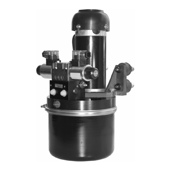
IMPORTANT SAFETY INFORMATION Failure to install and maintain this equipment in accordance with the in- structions contained in this Manual could result in damage or injury. This equipment must be installed and maintained by a person who is qualified to do so. This equipment is only for use with marine Auto pilots within the limitations stated in the following pages. - Page 5 DESCRIPTION "PC45" constant running type gear pumps are driven by 12 or 24 volt dc permanent magnet fan cooled motors. Flow reversal is achieved by switching a double acting solenoid valve. Incorporated in the design are pilot operated check valves that prevent the pump being back driven by the manual steering system.
-
Page 6: Hydraulic Connections
HYDRAULIC CONNECTIONS The 'A' and 'B' ports are G1/4(BSP) parallel threaded, the 'R' port is G3/8 (BSP) parallel threaded. Use only bonded rubber/metal washers to seal the fittings. Do not use tapered adapters, sealing compound or P.T.F.E tape. Ports marked 'A' and 'B' are the service line connections to the ram, the pipe work and connections must be suitable for a 100 bar working pressure minimum rating. -
Page 7: Troubleshooting
COMMISSIONING CAUTION! Be aware of the danger of moving linkages and the risk of entrapment during this procedure. Bleed the system according to the Helm Pump Manufacturers instruc- tions. To aid clearing air from the electric pump please note the orienta- tion of the hydraulic/electrical connections -See installation data. - Page 8 Should service re- placement seals be required, a kit is available from your nearest dealer under the following part code: PC45-sk During disassembly carefully note the order of the components and keep everything scrupulously clean, especially the pump faces with the plastic shim gasket or o-ring.
- Page 9 Tank Filter O ring seal 9/16” A/F Nylock nut Brush holder Clamp ring 7/16” A/F Clamp ring nut torque to 6 lbs/ft (8.1 Nm)
-
Page 10: Technical Data
(ref. ‘Recommended oils) Supply Voltage: 12 / 24 VDC Current Limitation: Must be fitted with current overload. Minimum fuse/trip rating : PC45 FCU 24 = 40A PC45 FCU 12 = 50A Performance: Refer to graphs Installation: Under deck, horizontal or vertical (tank down) Horizontal only if fitted with isolation mounts. - Page 11 12V 1.0A 24V 0.5A Reservoir Port 'R': G3/8 (BSP) Parallel Cylinder Ports 'A' & 'B': G1/4 (BSP) Parallel EMC Protection: BS EN 60945:2002 (DC) Ignition protection: BS EN 28846:1993 Part Nos: PC45 FCU 24 (550W) PC45 FCU 12 (405W) Weight: 12kg...
-
Page 12: Installation Details
INSTALLATION DETAILS Ø193mm Relief Valve Oil Filler / Breather Or Connection to Helm Pump Speed Control Cylinder Port A Cylinder Port B... -
Page 13: Wiring Details
TYPICAL PERFORMANCE (WITH FLOW CONTROL SET TO MAXIMUM) WIRING DETAILS Coil Wiring Diagram Autopilot A & B - Course output C - Pump engage (Clutch) output Solenoid Coil B Contactor Motor Fuse - 35A rotation Battery Attach leads to contactor as shown RED motor lead BLACK motor lead Use wire guage - 2.5mm Min... - Page 14 TYPICAL ARRANGEMENTS Primary Steering Helm pump with Integral check valve Steering Cylinder Secondary Steering Unloader valve (order R2345-O) filler/breather Steering Cylinder...
-
Page 15: General Information
GENERAL INFORMATION Keep this manual in safe place. Quote the model and serial numbers in all correspondence. Model Number: _____________________________________ Serial Number:: _____________________________________ Date of Purchase: _____________________________________ Dealer:: _____________________________________ _____________________________________ _____________________________________ _____________________________________ END OF LIFE DISPOSAL Please dispose of End of Life items responsibly. In the event that you are unable to use your nearest local authority civic amenity sites to recycle, units can be returned to us at the address on the back cover. -
Page 16: Contact Details
CONTACT DETAILS Hydraulic Projects Limited Dawlish Business Park Dawlish Devon EX7 0NH United Kingdom Telephone +44 (0)1626 863634 +44(0)1626 866283 Email sales@hypro.co.uk www.hypro.co.uk...
Need help?
Do you have a question about the PC45 and is the answer not in the manual?
Questions and answers