Table of Contents
Advertisement
Quick Links
Advertisement
Table of Contents

Subscribe to Our Youtube Channel
Related Manuals for Teracom TCW242-S


Summary of Contents for Teracom TCW242-S
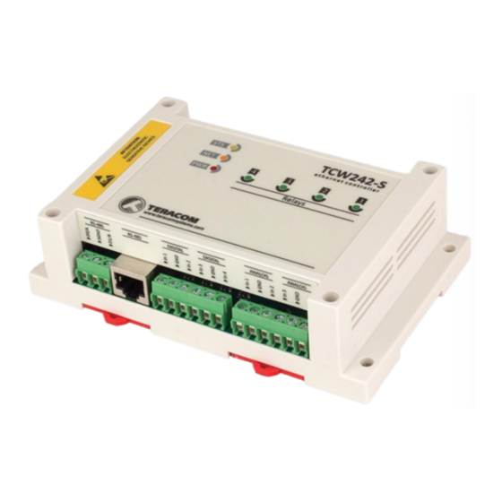
- Page 2 1. Introduction TCW242-S is an industrial IoT (Internet Of Things) module with Ethernet connectivity and data logging capability. All monitored parameters can be seen as numbers and as graphs. The device has 4 digital inputs, 4 analog inputs, an RS-485 interface for MODBUS RTU sensors, and 4 relays.
-
Page 3: Specifications
4. Specifications Physical characteristics Dimensions: 145 x 90 x 40 mm Weight: 200 g Environmental limits Operating temperature range: -20 to 55°C Storage temperature range: -25 to 60°C Operating relative humidity range: 10 to 80% (non-condensing) Warranty Warranty period: 3 years Power supply Operating voltage range (including -15/+20% according to IEC 62368-1): 10 to 28 VDC Current consumption: 0.35A @ 12VDC (without MODBUS RTU sensors powering) -
Page 4: Led Indicators
Appendix A, this provides ventilation and electrical isolation TCW242-S can be mounted to a standard (35mm by 7.55mm) DIN rail. Attach the controller to the DIN rail by hooking the hook on the back of the enclosure to the DIN rail and then snap the bottom hook into place. -
Page 5: Power Supply Connection
Pin6 – Analog In 4 6.2.1. Power supply connection TCW242-S is designed to be supplied by adapter SYS1308(N)-2412-W2E or similar, intended for use in the conditions of overvoltage category II, and prior assessed for compliance with safety requirements. The power supply equipment shall be resistant to short circuits and overload in a secondary circuit. -
Page 6: Digital Inputs Connection
“dry contact” outputs – door contact switch, push-button, PIR detector, etc. The following picture illustrates how a dry contact switch can be connected to the input of TCW242-S. One side of the contact is connected to “Digital In” and another side is connected to “GND” terminals. - Page 7 “MODBUS over Serial Line Specification and Implementation Guide” available on www.modbus.org. It is mandatory to use 120ohms line terminators at both ends of the bus. TCW242-S incorporates one of the terminators and should be placed at one end. So the client should only take care of terminating at the other end of the line.
-
Page 8: Network Connection
6.2.5. Network connection The Ethernet port of TCW242-S should be connected to 10/100 Base-T Ethernet hub, switch, or router. For configuration, TCW242-S may be connected directly to the Ethernet port on a computer. The device support Auto-MDIX and it is not necessary to use a “crossover” cable, standard “straight- through”... - Page 9 Communication with TCW242-S can be established by assigning a temporary IP address to the computer. For computers with Windows OS assigning of IP address is made in “Local area connection properties”: This address should be on the same network - for example 192.168.1.3: To get access to the web interface, you should type http://192.168.1.2 into the browser.
-
Page 10: Web Interface
If the network settings are correct, the login pop-up window will appear: Authorization data must be entered (by default username=admin, password=admin). It is recommended to change the username and password to prevent unauthorized access to the controller. All TCW controllers connected to LAN can be easily found by a free tool “TCW discoverer”. It is available for Win and Mac operating systems and can be downloaded from www.teracomsystems.com. - Page 11 8.1.1. Channels and relays This page displays the status of relays and all monitored channels – their values and alarm status. The information is updated on the refresh interval. 8.1.2. Alarms This page displays the status of all alarms. The information is updated on the refresh interval. 8.1.3.
- Page 12 It is important to know that the information on graphs is static, it is not updated whit the newest values. If you want to see the last information, the page should be reloaded. The information can be exported in a CSV file. 8.2.
- Page 13 decreases the time until the sensor stops responding. In order for the operation sustainability, the found time should be increased with for example 20%. 8.2.2.2. Modbus RTU sensors This section allows you to add, delete or edit MODBUS RTU sensors/registers. All these are primary parameters and can be used in forming channels.
-
Page 14: Analog Inputs
8.2.3.1. Analog inputs TCW242-S has 4 analog inputs. All they are isolated from the power supply but use the same ground. Every analog input can work in voltage (0-10V) or current loop mode (0-20mA). For every analog input Multiplier and Offset can be set. They work as follows: Value = (Raw_Value * Multiplier) + Offset. -
Page 15: Digital Inputs
8.2.3.2. Digital inputs TCW242-S has 4 digital inputs. All they are isolated from the power supply but use the same ground. Every digital input can work in OPEN/CLOSE or COUNTER mode. In COUNTER mode, counting can be made on rising, falling, or both edges. - Page 16 For locally activated relays a text description of the controlling parameter is displayed rather than buttons. Parameters for local relay activation can be set in “Setup-Input/Output-Relay Outputs”. 8.2.4. Channels This section allows you to add, delete or edit channels. All they can be monitored on monitoring pages and their values can be recorded periodically by the data logger.
- Page 17 The “Limit” indicates the border of the working range for the observed channel. A trigger condition occurs when the value goes higher (“Sign” is “≥”) and lower (“Sign” is “<”) than the limit. In both cases, the monitored parameter goes out of range. Coming back in range for the observed channel is considered when the value goes higher than Limit + Hysteresis (“Sign”...
- Page 18 8.2.6. System On this page, some general system parameters can be set up. System name, system location, and system contact are used for device identification. They are presented in SNMP three and XML/JSON status files. WEB access authentication by default is active with admin/admin details. HTTP port for WEB access by default is 80 but it can be changed.
- Page 19 For automatic clock synchronization, the controller supports NTP (Network Time Protocol). By default NTP synchronization is disabled, server – time.google.com, Time zone +00:00, and interval of 12 hours. 8.3.2. SNMP TCW242-S supports SNMPv2 and SNMPv3. The default parameters are: SNMP disabled...
- Page 20 Authentication and privacy (authPriv) - usually for downloading secrets. User-based Authentication Mechanism is based on the following: MD5 message-digest algorithm in HMAC; SHA, an optional alternative algorithm; None authentication. User-based Privacy Mechanism is based on the following: Data Encryption Standard (DES); Advanced Encryption Standard (AES);...
- Page 21 8.3.3. Logger The logger works in three modes – Time, Alarm, and Time&Alarm. The mode specifies what initiates a record in the logger’s memory. In Time mode, records are made periodically on “Log interval” time. In Alarm mode, records are made on every alarm condition.
- Page 22 More about the logger can be found in the Datalogger section. 8.3.4. HTTP Post TCW242-S can periodically upload an XML/JSON file to a dedicated server, using HTTP or HTTPS Post. The HTTPS is over TLS 1.0, TLS 1.1, and TLS 1.2 with RSA as a key exchange/agreement and authentication.
- Page 23 The “Key” field is user-defined. Its value is sent in an XML/JSON file and can be used for device identification. If the “Process Answer” option is enabled, TCW242-S will execute the commands, sent by the remote server as an answer to HTTP/HTTPS Post.
-
Page 24: Dynamic Dns
With the above setting, there will be an event for 2 hours between Monday 23:00:00 and Tuesday 01:00:00. 8.3.6. Dynamic DNS TCW242-S supports the following DNS services – DynDNS, No-IP, and DNS-O-Matric. With dynamic DNS, TCW242-S can be accessed from the Internet having only a dynamic public IP address. 8.3.7. MODBUS TCW242-S supports MODBUS TCP/IP. - Page 25 Attention! Don’t turn off the power supply during the update. Turning off the power supply will damage the device. 8.5. Logout The TCW242-S support a few session, but the good practice is to log out after finishing the work. TCW242-S_R1.0 – July 2021 Page 25...
- Page 26 LAN. Each controlled device, at all times, executes a software component called an agent which reports information via SNMP to the manager. The TCW242-S can be configured and monitored through SNMP. This could be done using every SNMP v.2 or v.3 compatible program. Parameters that can be changed, are grouped according to their functions in the tables below.
- Page 27 !.8.2.2.3.1.1.6.?.0 digInpCloseToOpenDelay.? read-write Digital input Close To Open delay Integer32(0..60000) !.8.2.2.3.1.1.7.?.0 digInpOpenToCloseDelay.? read-write Digital input Open To Close delay Integer32(0..60000) !.8.2.2.3.1.1.8.?.0 digInpCounterInitValue.? read-only Digital input counter initial value Integer32 !.8.2.2.3.1.1.9.?.0 digInpValue.? read-only Digital input value Unsigned32 setup -> parameters -> relaySetup -> relOutSetupTable -> relOutSetupEntry -> relOutSetupIndex 1 to 4 replace “?“...
- Page 28 s14(16), s15(17), s16(18), s17(19), s18(20), s19(21), s20(22), s21(23), s22(24), s23(25), s24(26),a01(27), a02(28), a03(29), a04(30), a05(31), a06(32),d01(33), d02(34), d03(35), d04(36)} INTEGER {none(0), multiplication(1), !.8.3.1.1.1.7.?.0 chOP2.? read-write Channel operand 2 division(2), sum(3), subtract(4)} !.8.3.1.1.1.8.?.0 chCoef1.? read-write Channel coefficient 1 x1000 in Integer format Integer32 INTEGER {none(0), multiplication(1),...
- Page 29 v13(13), v14(14), v15(15), v16(16), v17(17), v18(18), v19(19), v20(20), v21(21), v22(22), v23(23), v24(24)} INTEGER{larger(1), !.8.3.3.1.1.10.?.0 alCond2Operand.? read-write Alarm condition 2 operand less(2)} !.8.3.3.1.1.11.?.0 alCond2Limit.? read-write Alarm condition 2 limit x1000 in Integer format Integer32 Alarm condition 2 hysteresis x1000 in Integer !.8.3.3.1.1.12.?.0 alCond2Hys.? read-write...
- Page 30 9.2. HTTP API 9.2.1. HTTP Post TCW242-S can execute HTTP/HTTPS Post to upload XML/JSON files to a dedicated server. This functionality is very useful if the controller is behind the router without a public IP address or the user doesn’t have access to the router configuration. The server should have a public IP address.
- Page 31 See sections 9.2.4 XML file structure and 9.2.5 JSON file structure for details of files. HTTP Get can be sent at any time to TCW242-S if it is on the same network or it has appropriate routing. If there isn’t direct access to the device, HTTP Get can be sent immediately after HTTP/HTTPS Post receiving from the same device.
- Page 32 9.2.3. List of HTTP API commands Command Description dataf=x Data format XML/JSON for HHTP Post – 0 XML, 1 JSON pushtls=x HTTP(S) protocol, where x is 0 for HTTP and 1 for HTTPS purl1=yyy URL for HTTP Post to Server 1, where yyy is a full path to the PHP file.
- Page 33 9.2.4. XML file structure <Monitor> <DeviceInfo> <DeviceName>TCW242-S</DeviceName> <HostName>TCW242S </HostName> <ID>5c:32:c5:00:a8:0b</ID> <FwVer>TCW242S-v1.000</FwVer> <MnfInfo>www.teracomsystems.com</MnfInfo> <SysContact>info@teracomsystems.com</SysContact> <SysName>TCW242S</SysName> <SysLocation>Location</SysLocation> </DeviceInfo> <CH> <CH1> <type>0</type> <description>Temperature</description> <value>24.386</value> <unit>°C</unit> <alarmbin>4</alarmbin> <alarm>Minor</alarm> <selch>3</selch> </CH1> <CH2> <type>0</type> <description>Humidity</description> <value>51.323</value> <unit>RH</unit> <alarmbin>1</alarmbin> <alarm>Normal</alarm> <selch>4</selch> </CH2> <CH3> <type>2</type> <description>Digital Input 1</description>...
- Page 34 </CH7> <CH8> <type>0</type> <description>V08</description> <value>---</value> <unit/> <alarmbin>0</alarmbin> <alarm/> <selch>0</selch> </CH8> <CH9> <type>0</type> <description>V09</description> <value>---</value> <unit/> <alarmbin>0</alarmbin> <alarm/> <selch>0</selch> </CH9> <CH10> <type>0</type> <description>V10</description> <value>---</value> <unit/> <alarmbin>0</alarmbin> <alarm/> <selch>0</selch> </CH10> <CH11> <type>0</type> <description>V11</description> <value>---</value> <unit/> <alarmbin>0</alarmbin> <alarm/> <selch>0</selch> </CH11> <CH12> <type>0</type> <description>V12</description> <value>---</value>...
- Page 35 <unit/> <alarmbin>0</alarmbin> <alarm/> <selch>0</selch> </CH16> <CH17> <type>0</type> <description>V17</description> <value>---</value> <unit/> <alarmbin>0</alarmbin> <alarm/> <selch>0</selch> </CH17> <CH18> <type>0</type> <description>V18</description> <value>---</value> <unit/> <alarmbin>0</alarmbin> <alarm/> <selch>0</selch> </CH18> <CH19> <type>0</type> <description>V19</description> <value>---</value> <unit/> <alarmbin>0</alarmbin> <alarm/> <selch>0</selch> </CH19> <CH20> <type>0</type> <description>V20</description> <value>---</value> <unit/> <alarmbin>0</alarmbin> <alarm/> <selch>0</selch> </CH20>...
- Page 36 </CH> <AL> <AL1> <description>AL01-T</description> <alarmbin>4</alarmbin> <alarm>Minor</alarm> <assign>1</assign> </AL1> <AL2> <description>AL02-H</description> <alarmbin>1</alarmbin> <alarm>Normal</alarm> <assign>2</assign> </AL2> <AL3> <description>AL03</description> <alarmbin>0</alarmbin> <alarm/> <assign>0</assign> </AL3> <AL4> <description>AL04-DI1</description> <alarmbin>0</alarmbin> <alarm/> <assign>0</assign> </AL4> <AL5> <description>AL05-Humidity</description> <alarmbin>1</alarmbin> <alarm/> <assign>2</assign> </AL5> <AL6> <description>AL06</description> <alarmbin>0</alarmbin> <alarm/> <assign>0</assign> </AL6> <AL7> <description>AL07</description> <alarmbin>0</alarmbin>...
- Page 37 <alarm/> <assign>0</assign> </AL13> <AL14> <description>AL14</description> <alarmbin>0</alarmbin> <alarm/> <assign>0</assign> </AL14> <AL15> <description>AL15</description> <alarmbin>0</alarmbin> <alarm/> <assign>0</assign> </AL15> <AL16> <description>AL16</description> <alarmbin>0</alarmbin> <alarm/> <assign>0</assign> </AL16> <AL17> <description>AL17</description> <alarmbin>0</alarmbin> <alarm/> <assign>0</assign> </AL17> <AL18> <description>AL18</description> <alarmbin>0</alarmbin> <alarm/> <assign>0</assign> </AL18> <AL19> <description>AL19</description> <alarmbin>0</alarmbin> <alarm/> <assign>0</assign> </AL19> <AL20> <description>AL20</description>...
- Page 38 <assign>0</assign> - alarm not assigned to any channel; <selch>0</selch> - channel is not displayed on Monitoring -> Channels section 9.2.5. JSON file structure "Monitor": { "DeviceInfo": { "DeviceName": "TCW242-S", "HostName": "TCW242S ", "ID": "5c:32:c5:00:a8:0b ", "FwVer": "TCW242S-v1.000", "MnfInfo": "www.teracomsystems.com", "SysContact": "info@teracomsystems.com", "SysName": "TCW242S",...
- Page 39 "CH3": { "type": "2", "description": "Digital Input 1", "value": "OPEN", "unit": "", “alarmbin”: "1", “alarm”: "Normal", "selch":"31" "CH4": { "type": "0", "description": "V04", "value": "---", "unit": "", “alarmbin”: "0", “alarm”: "", "selch":"0" "CH5": { "type": "0", "description": "V05-Voltage", "value": "0.000", "unit": "V", “alarmbin”: "1", “alarm”: "Normal",...
- Page 40 “alarmbin”: "0", “alarm”: "", "selch":"0" "CH12": { "type": "0", "description": "V12", "value": "---", "unit": "", “alarmbin”: "0", “alarm”: "", "selch":"0" "CH13": { "type": "0", "description": "V13", "value": "---", "unit": "", “alarmbin”: "0", “alarm”: "", "selch":"0" "CH14": { "type": "0", "description": "V14", "value": "---", "unit": "", “alarmbin”: "0",...
- Page 41 "type": "0", "description": "V20", "value": "---", "unit": "", “alarmbin”: "0", “alarm”: "", "selch":"0" "CH21": { "type": "0", "description": "V21", "value": "---", "unit": "", “alarmbin”: "0", “alarm”: "", "selch":"0" "CH22": { "type": "0", "description": "V22", "value": "---", "unit": "", “alarmbin”: "0", “alarm”: "", "selch":"0"...
- Page 42 "description": "AL06", “alarmbin”: "0", “alarm”: "", "assign":"0" "AL7": { "description": "AL07", “alarmbin”: "0", “alarm”: "", "assign":"0" "AL8": { "description": "AL08", “alarmbin”: "0", “alarm”: "", "assign":"0" "AL9": { "description": "AL09", “alarmbin”: "0", “alarm”: "", "assign":"0" "AL10": { "description": "AL10", “alarmbin”: "0", “alarm”: "", "assign":"0"...
- Page 43 "AL19": { "description": "AL19", “alarmbin”: "0", “alarm”: "", "assign":"0" "AL20": { "description": "AL20", “alarmbin”: "0", “alarm”: "", "assign":"0" "AL21": { "description": "AL21", “alarmbin”: "0", “alarm”: "", "assign":"0" "AL22": { "description": "AL22", “alarmbin”: "0", “alarm”: "", "assign":"0" "AL23": { "description": "AL23", “alarmbin”: "0", “alarm”: "", "assign":"0"...
-
Page 44: Modbus Tcp/Ip
9.3. MODBUS TCP/IP Modbus protocol is a serial communications protocol originally published by Modicon in 1979. It is used to establish master-slave/client-server communication between intelligent devices. Modbus is often used to connect a supervisory computer with a remote terminal unit (RTU) in supervisory control and data acquisition (SCADA) systems. -
Page 45: Exception Codes
03: The Function Code 3 (read Channel 1 Holding Registers) 04: The number of data bytes to follow (2 registers x 2 bytes each = 4 bytes) 41C3 B021: 4 bytes value All holding registers with float values are sent in big-endian. In the example above, the value of 24.4610004 is sent. - Page 46 Discrete Write Relay 4 Read Channel 1 32-bit Float Read Channel 2 32-bit Float Read Channel 3 32-bit Float Read Channel 4 32-bit Float Read Channel 5 32-bit Float 32-bit Float Read Channel 6 Read Channel 8 32-bit Float Read Channel 9 32-bit Float Read Channel 10 32-bit Float...
- Page 47 32-bit unsign int Read Channel 23 Read Channel 24 32-bit unsign int Read Channel 1 Dimension 1000 16 bytes UTF-8 Read Channel 2 Dimension 1008 16 bytes UTF-8 Read Channel 3 Dimension 1016 16 bytes UTF-8 Read Channel 4 Dimension 1024 16 bytes UTF-8 1032...
-
Page 48: Data Logger
5160 Read Channel 21 Description 16 bytes UTF-8 Read Channel 22 Description 5168 16 bytes UTF-8 Read Channel 23 Description 5176 16 bytes UTF-8 Read Channel 24 Description 5184 16 bytes UTF-8 10. Data Logger The logger utilizes a circular buffer in FLASH memory. When it is full, the new data overwrites the oldest one. -
Page 49: Factory Default Settings
An example of the log file /fragment alarms - values/descriptions/: ID;Time;Type;…Al1/AL1-T;Al2/AL2-H;Al3;Al4;Al5;Al6;Al7;Al8;Al9;Al10;Al11;Al12;Al13;Al14;Al15;Al16;Al17;Al18;Al19;Al20;Al21;Al22;Al23;Al24..25114;19.07.2021,16:49:49;Time;….3;5;0;0;0;0;;;;;;;;;;;;;;;;;; 11. Factory default settings TCW242-S can be restored to its original factory default settings in 3 different ways. 11.1. Factory default from the WEB interface If the button “Factory default” from Administration->Backup/Restore is pressed, all parameters return to factory default except Network settings. -
Page 50: Environment Information
The factory default settings are: Username admin Password admin IP Address 192.168.1.2 Subnet Mask 255.255.255.0 Default Gateway 192.168.1.1 SNMPConfiguration disabled readCommunity public writeCommunity private Analog inputs unit voltage Analog inputs multiplier 1.000 Analog inputs ofset 0.000 Analog inputs mode Voltage Digital inputs mode Open/Closed 12. -
Page 51: Maintenance
Teracom does not guarantee the successful operation of the product if the product was used under conditions deviating from the product specifications. To ensure that the device works correctly follow the steps below: Ensure that the device is installed correctly, refer to this document;... - Page 52 Appendix A Fig.1 Fig.2 TCW242-S_R1.0 – July 2021 Page 52...
Need help?
Do you have a question about the TCW242-S and is the answer not in the manual?
Questions and answers