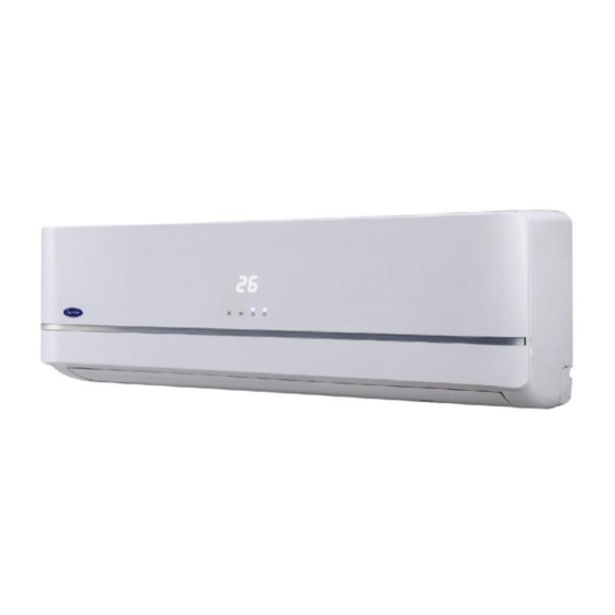
Summary of Contents for Carrier 38HVM109303
- Page 1 WALL MOUNTED AIR CONDITIONER SERVICE MANUAL 11M INVERTER This manual applies to the models: 42HVM109303 / 38HVM109303(P) 42HVM112303 / 38HVM112303(P) 42HVM118303 / 38HVM118303(P) 42HVM124303 / 38HVM124303(P)
-
Page 2: Table Of Contents
CONTENTS 1. Precaution .............................. 3 1.1 Safety Precaution .......................... 3 1.2 Warning ............................3 2. Function ..............................7 3. Dimension .............................. 8 3.1 Indoor Unit ............................. 8 3.2 Outdoor Unit ..........................10 4. Refrigerant Cycle Diagram ........................11 5. Wiring Diagram ............................ 12 5.1 Indoor Unit ........................... -
Page 3: Precaution
1. Precaution 1.1 Safety Precaution To prevent injury to the user or other people and property damage, the following instructions must be followed. Incorrect operation due to ignoring instruction will cause harm or damage. Before service the unit, be sure to read this service manual at first. 1.2 Warning ... - Page 4 condenser and evaporator. For installation, always contact the dealer or an authorized service center. Do not install the product on a defective installation stand. Be sure the installation area does not deteriorate with age. If the base collapses, the air conditioner could fall with it, causing property damage, product failure, and personal injury.
- Page 5 There is risk of property damage, failure of product, or electric shock. Do not open the inlet grill of the product during operation. (Do not touch the electrostatic filter, if the unit is so equipped.) There is risk of physical injury, electric shock, or product failure. ...
- Page 6 could cause product malfunction or inefficient operation. Operational Do not expose the skin directly to cool air for long time. (Do not sit in the draft). Do not use the product for special purposes, such as preserving foods, works of art etc. It is a consumer air conditioner, not a precision refrigerant system.
-
Page 7: Function
2. Function Model Names of Indoor/Outdoor Units Capacity Indoor units Outdoor units MS11M-09HRFN1-MW0W MOC-09HFN1-MW0W MS11M-12HRFN1-MV0W MOC-12HFN1-MV0W Inverter MS11M-18HRFN1-MU0W MOF-18HFN1-MU0W MS11M-24HRFN1-MT0W MOG-24HFN1-MT0W Filter Silent mode(O) Cold catalyst filter Ionizer(O) Louver Position Memory Function Plasma(O) Refrigerant Leakage Detect Silver Ico Filter(O) Mono&Multi compatible Vitamin C Filter(O) Self-diag. -
Page 8: Dimension
3. Dimension 3.1 Indoor Unit Model MS11M-09HRFN1-MW0W MS11M-12HRFN1-MV0W MS11M-18HRFN1-MU0W MS11M-24HRFN1-MT0W 1186 Model L(mm) R(mm) H(mm) Dimension of installation hole(mm) MS11M-09HRFN1-MW0W ¢65 MS11M-12HRFN1-MV0W... - Page 9 Model L(mm) R(mm) H(mm) Dimension of installation hole(mm) ¢65 MS11M-18HRFN1-MU0W Model L(mm) R(mm) H(mm) Dimension of installation hole(mm) ¢65 MS11M-24HRFN1-MT0W...
-
Page 10: Outdoor Unit
3.2 Outdoor Unit More than 30cm More than 60cm (Service space) More than 30cm More than 60cm More than 70cm Model MOC-09HFN1-MW0W MOC-12HFN1-MV0W MOF-18HFN1-MU0W MOG-24HFN1-MT0W... -
Page 11: Refrigerant Cycle Diagram
4. Refrigerant Cycle Diagram INDOOR OUTDOOR Electronic Expansion Valve LIQUID SIDE CAPILIARY TUBE 2-WAY VALVE HEAT HEAT EXCHANGE EXCHANGE (EVAPORATOR) (CONDENSER) GAS SIDE REVERSING VALVE 3-WAY VALVE ACCUMULATOR COOLING COMPRESSOR HEATING... -
Page 12: Wiring Diagram
5. Wiring Diagram 5.1 Indoor Unit MS11M-09HRFN1-MW0W, MS11M-12HRFN1-MV0W, MS11M-18HRFN1-MU0W MS11M-24HRFN1-MT0W... -
Page 13: Outdoor Unit
5.2 Outdoor Unit MOC-09HFN1-MW0W, MOC-12HFN1-MV0W MOF-18HFN1-MU0W... - Page 14 MOG-24HFN1-MT0W...
-
Page 15: Installation Details
6 Installation Details 6.1 Wrench torque sheet for installation Outside diameter Torque Additional tightening torque inch N.cm N.cm Ф6.35 1500(153kgf.cm) 1600(163kgf.cm) Ф9.52 2500(255kgf.cm) 2600(265kgf.cm) Ф12.7 3500(357kgf.cm) 3600(367kgf.cm) Ф15.9 4500(459kgf.cm) 4700(479kgf.cm) Ф19 6500(663kgf.cm) 6700(683kgf.cm) 6.2 Connecting the cables The power cord of connect should be selected according to the following specifications sheet. Rated current of appliance Nominal cross-sectional area (mm²) >3 and ≤6... -
Page 16: Pipe Length And The Elevation
6.3 Pipe length and the elevation The pipe length and refrigerant amount: Pipe size Standard Max. Max. Additional Model length Elevation Length refrigerant Liquid B (m) A (m) (g/m) MS11M-09HRFN1-MW0W+MOC-09HFN1-MW0 3/8’’ 1/4’’ (Ф9.52) (Ф6.35) MS11M-12HRFN1-MV0W+MOC-12HFN1-MV0W 1/2’’ 1/4’’ MS11M-18HRFN1-MU0W+MOF-18HFN1-MU0W (Ф12.7) (Ф6.35) 5/8’’... -
Page 17: Installation For The First Time
6.4 Installation for the first time Air and moisture in the refrigerant system have undesirable effects as below: ● Pressure in the system rises. ● Operating current rises. ● Cooling or heating efficiency drops. ● Moisture in the refrigerant circuit may freeze and block capillary tubing. ●... - Page 18 the meter does not indicate -0.1Mpa after pumping 30 minutes, it should be pumped 20 minutes more. If the pressure can’t achieve -0.1Mpa after pumping 50 minutes, please check if there are some leakage points. Fully close the handle Lo valve of the manifold valve and stop the operation of the vacuum pump. Confirm that the gauge needle does not move (approximately 5 minutes after turning off the vacuum pump).
- Page 19 Close the valve on the charging cylinder and discharge the refrigerant by loosening the flare nut on the 2-way valve approximately 45’ until the gauge indicates 0.3 to 0.5 Mpa. 6). Disconnect the charge set and the charging cylinder, and set the 2-way and 3-way valves to the open position.
-
Page 20: Adding The Refrigerant After Running The System For Many Years
6).When the electronic scale displays the proper weight (refer to the table), disconnect the charge hose from the 3-way valve’s service port immediately and turn off the air conditioner before disconnecting the hose. 7). Mount the valve stem caps and the service port Use torque wrench to tighten the service port cap to a torque of 18N.m.


Need help?
Do you have a question about the 38HVM109303 and is the answer not in the manual?
Questions and answers