Table of Contents

Subscribe to Our Youtube Channel
Related Manuals for Aaeon RTC-1000D1


Summary of Contents for Aaeon RTC-1000D1
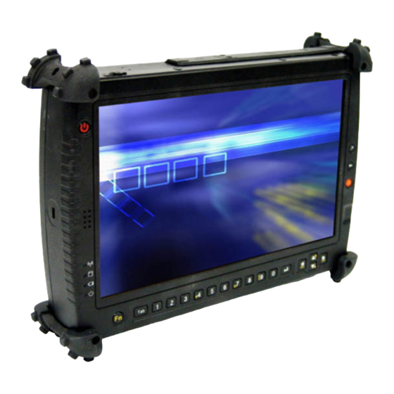
- Page 1 R T C - 1 0 0 0 D 1 RTC-1000D1 ® Intel Core™ Duo U2500 1.2 GHz Processor Rugged Tablet Computer with 10.2” WSVGA Color TFT LCD 2 USB2.0, 1 Mini USB 1 COM, 1 VGA RTC-1000D1 Manual 3rd Ed May 14, 2014...
- Page 2 AAEON assumes no liabilities resulting from errors or omissions in this document, or from the use of the information contained herein. AAEON reserves the right to make changes in the product design without notice to its users.
- Page 3 R u g g e d T a b l e t C o m p u t e r R T C - 1 0 0 0 D 1 Acknowledgments All other products’ name or trademarks are properties of their respective owners.
- Page 4 Packing List Before you begin operating your PC, please make sure that the following materials are enclosed: RTC-1000D1 Rugged Tablet Computer with a Hard Disk Drive & 1GB/ 2GB SODIMM Memory Card AC Adapter with Power Cord ...
- Page 5 R u g g e d T a b l e t C o m p u t e r R T C - 1 0 0 0 D 1 Options The following items are normally optional, but some vendors may include them in the standard package.
- Page 6 R u g g e d T a b l e t C o m p u t e r R T C - 1 0 0 0 D 1 Safety & Maintenance You can use your Rugged Tablet Computer under a wide range of environmental conditions.
- Page 7 R u g g e d T a b l e t C o m p u t e r R T C - 1 0 0 0 D 1 outlet. Never push foreign objects into the RTC through any of the slots or openings.
- Page 8 R u g g e d T a b l e t C o m p u t e r R T C - 1 0 0 0 D 1 Below Table for China RoHS Requirements 产品中有毒有害物质或元素名称及含量 AAEON Panel PC/ Workstation 有毒有害物质或元素 部件名称 铅...
-
Page 9: Table Of Contents
R u g g e d T a b l e t C o m p u t e r R T C - 1 0 0 0 D 1 Contents Chapter 1 Introduction 1.1 Getting Started ............1-2 1.2 Features ..............1-3 1.3 Where to Look For Information ......... - Page 10 R u g g e d T a b l e t C o m p u t e r R T C - 1 0 0 0 D 1 3.2 Top Side Connectors..........3-4 Chapter 4 Power Management 4.1 Power Management ..........4-2 4.2 When to Replace the Battery ........
-
Page 11: Chapter 1 Introduction
R u g g e d T a b l e t C o m p u t e r R T C - 1 0 0 0 D 1 Chapter Introduction 1- 1 Chapter 1 Introduction... -
Page 12: Getting Started
R u g g e d T a b l e t C o m p u t e r R T C - 1 0 0 0 D 1 1.1 Getting Started Congratulations on your purchase of a Rugged Tablet Computer (RTC). -
Page 13: Features
R u g g e d T a b l e t C o m p u t e r R T C - 1 0 0 0 D 1 1.2 Features Software Included ® Widows Embedded Standard 2009 Edition which includes: ®... -
Page 14: Where To Look For Information
R u g g e d T a b l e t C o m p u t e r R T C - 1 0 0 0 D 1 1.3 Where to Look For Information About Your RTC This User’s Manual describes the key elements of your RTC. New users can find a simple step-by-step orientation in the Quick Start section of this Chapter. -
Page 15: Quick Start
R u g g e d T a b l e t C o m p u t e r R T C - 1 0 0 0 D 1 1.4 Quick Start Turning on the Rugged Tablet Computer for the First Time Connect the AC adapter power cord to the AC adapter. -
Page 16: Loading Windows
R u g g e d T a b l e t C o m p u t e r R T C - 1 0 0 0 D 1 1.5 Loading Windows The following section is for the Windows operating system only. If you are installing a different operating system, please check with your vendor for installation details. -
Page 17: Adjusting The Volume
R u g g e d T a b l e t C o m p u t e r R T C - 1 0 0 0 D 1 1.6 Adjusting the Volume You can adjust the volume with hot key: ... -
Page 18: Adjusting The Brightness
R u g g e d T a b l e t C o m p u t e r R T C - 1 0 0 0 D 1 1.7 Adjusting the Brightness Use the following hot key combinations to adjust the LCD panel brightness: ... -
Page 19: Turning Off Your Rtc
R u g g e d T a b l e t C o m p u t e r R T C - 1 0 0 0 D 1 1.8 Turning off your RTC Turning off the RTC properly is important to maintain the RTC. On the Start menu, click Shut Down. -
Page 20: Chapter 2 Getting Started
R u g g e d T a b l e t C o m p u t e r R T C - 1 0 0 0 D 1 Chapter Getting Started Chapter 2 Getting Started... - Page 21 R u g g e d T a b l e t C o m p u t e r R T C - 1 0 0 0 D 1 Hardware and Software This chapter introduces the different components and controls of your RTC, including the hardware components, the software, and the audio and video systems.
-
Page 22: Appearance
R u g g e d T a b l e t C o m p u t e r R T C - 1 0 0 0 D 1 2.1 Appearance Front View Power Button Security Button Speaker Backspace Button Quick Launch Button Status Indicator Finger Print Scanner... - Page 23 R u g g e d T a b l e t C o m p u t e r R T C - 1 0 0 0 D 1 Right and Bottom View CompactFlash™ Card Slot RS-232 Serial Port Microphone-in Docking Connector Audio-out...
-
Page 24: Power Indicators
R u g g e d T a b l e t C o m p u t e r R T C - 1 0 0 0 D 1 2.2 Power Indicators The power indicators show which power source the system is using. They also show battery status and low battery power alerts. -
Page 25: Front View Buttons
R u g g e d T a b l e t C o m p u t e r R T C - 1 0 0 0 D 1 2.3 Front View Buttons The seven hot keys are unique features of your RTC. The function as follows: Icon Function... - Page 26 R u g g e d T a b l e t C o m p u t e r R T C - 1 0 0 0 D 1 Tab Button Under Normal Input Mode: Same function as on a standard keyboard. Under Calculation Mode: Role as “Period”...
-
Page 27: Function Keys
R u g g e d T a b l e t C o m p u t e r R T C - 1 0 0 0 D 1 2.4 Function Keys Hold the Fn Key while pressing the function key. Function Key Description Fn + Down... -
Page 28: Quick Start Button
R u g g e d T a b l e t C o m p u t e r R T C - 1 0 0 0 D 1 2.5 Quick Start Button Function+1 & Quick-Launch Button: Can be customized to launch specific win-base program assigned in Quick Start Button tool. -
Page 29: Connecting The Printer
R u g g e d T a b l e t C o m p u t e r R T C - 1 0 0 0 D 1 3. Select execute file and press open. Note: Up to 2 “ Quick Launch” function keys can be assigned to specific application depends on BIOS configuration. -
Page 30: Compactflash (Cf) Card Slot
R u g g e d T a b l e t C o m p u t e r R T C - 1 0 0 0 D 1 Some cards may be inserted with power on, while others require that the RTC be turned off. - Page 31 R u g g e d T a b l e t C o m p u t e r R T C - 1 0 0 0 D 1 Replacing a Memory Card Warning: Memory modules can be easily damaged by static electricity.
- Page 32 R u g g e d T a b l e t C o m p u t e r R T C - 1 0 0 0 D 1 Inserting a Memory Card Hold the memory card by its edges with the edge-connector side towards the slot.
-
Page 33: Communication Components
R u g g e d T a b l e t C o m p u t e r R T C - 1 0 0 0 D 1 2.10 Communication Components The system includes built-in Fax/Modem. Fax/Modem A phone jack on the top side of the RTC allows you to connect to the Internet to send and receive data. -
Page 34: Chapter 3 Making Connections
R u g g e d T a b l e t C o m p u t e r R T C - 1 0 0 0 D 1 Chapter Making Connections Chapter 3 Making Connections... -
Page 35: Right Side Connectors
R u g g e d T a b l e t C o m p u t e r R T C - 1 0 0 0 D 1 Making connections Your RTC is equipped with a full array of ports and connectors, including standard input/output (I/O) ports for quickly and easily adding peripheral devices such as printers, keyboards, and mice. - Page 36 R u g g e d T a b l e t C o m p u t e r R T C - 1 0 0 0 D 1 Press the eject button to release the card. 4. USB (Universal Serial Bus) Ports The Universal Serial Bus (USB) is the latest standard for attaching monitors, input devices, scanners, and other devices to a PC.
-
Page 37: Top Side Connectors
R u g g e d T a b l e t C o m p u t e r R T C - 1 0 0 0 D 1 3.2 Top Side Connectors 1. LAN RJ-45 Jack With the built-in Ethernet LAN combo, you can make LAN connections without installing PC cards. - Page 38 R u g g e d T a b l e t C o m p u t e r R T C - 1 0 0 0 D 1 3. Mini USB Port The Universal Serial Bus (USB) is the latest standard for attaching monitors, input devices, scanners, and other devices to a PC.
-
Page 39: Chapter 4 Power Management
R u g g e d T a b l e t C o m p u t e r R T C - 1 0 0 0 D 1 Chapter Power Management 4 - 1 Chapter 4 Power Management... - Page 40 R u g g e d T a b l e t C o m p u t e r R T C - 1 0 0 0 D 1 4.1 Power Management Checking the Battery Level You can check the remaining battery power in the Windows® battery status indicator located at the lower right-hand corner of the task tray.
- Page 41 R u g g e d T a b l e t C o m p u t e r R T C - 1 0 0 0 D 1 Low Battery Alarms How your RTC responds to a low battery condition is set under Start/ Control Panel / Power Options / Alarms.
-
Page 42: When To Replace The Battery
R u g g e d T a b l e t C o m p u t e r R T C - 1 0 0 0 D 1 4.2 When to Replace the Battery Over time, the battery's capacity gradually decreases. We recommend that you replace your battery when you notice that it begins to store significantly less charge. - Page 43 R u g g e d T a b l e t C o m p u t e r R T C - 1 0 0 0 D 1 Calibrating the Touch Screen 1. Click the Windows® Start button > Control Panel > Switch to Classic View >...
-
Page 44: Appendix A Statements
R u g g e d T a b l e t C o m p u t e r R T C - 1 0 0 0 D 1 Appendix Statements Appendix A Statements A-... - Page 45 R u g g e d T a b l e t C o m p u t e r R T C - 1 0 0 0 D 1 A.1 Statements Federal Communications Commission Statement This equipment has been tested and found to comply with the limits for a Class B digital device, pursuant to Part 15 of the FCC Rules.
- Page 46 R u g g e d T a b l e t C o m p u t e r R T C - 1 0 0 0 D 1 could void the user's authority to operate the equipment. CAUTION: Any changes or modifications not expressly approved by the party responsible for compliance could void the user's authority to operate the equipment.
- Page 47 R u g g e d T a b l e t C o m p u t e r R T C - 1 0 0 0 D 1 the telephone company to determine the maximum REN for the calling areas.
-
Page 48: European Notice
R u g g e d T a b l e t C o m p u t e r R T C - 1 0 0 0 D 1 message clearly contains in a margin at the top or bottom of each transmitted page or on the first page of the transmission, the date and time it is sent and an identification of the business or other entity, or other individual sending the message and the telephone... -
Page 49: Safety Caution
R u g g e d T a b l e t C o m p u t e r R T C - 1 0 0 0 D 1 (2000-09) • EN 60950-1: 2001+ All 2004 Regulatory statement (R&TTE / WLAN IEEE 802.11b & 802.11g) European standards dictate maximum radiated transmit power of 100mW EIRP and frequency range 2.400-2.4835GHz;... -
Page 50: Battery Disposal
R u g g e d T a b l e t C o m p u t e r R T C - 1 0 0 0 D 1 Do not use the telephone to report a gas leak in the vicinity of the leak. -
Page 51: Battery Caution
R u g g e d T a b l e t C o m p u t e r R T C - 1 0 0 0 D 1 A.6 Battery CAUTION Danger of explosion if battery is incorrectly replaced. Replace only with the same or equivalent type recommended by the manufacturer. - Page 52 R u g g e d T a b l e t C o m p u t e r R T C - 1 0 0 0 D 1 temperature. Otherwise, it will cause the damage of battery pack. In addition, the battery charging will not start if the battery pack is not in this temperature range.
Need help?
Do you have a question about the RTC-1000D1 and is the answer not in the manual?
Questions and answers