Advertisement
Quick Links
SSV WORKS, 201 N. Rice Ave Unit A, Oxnard, CA 93030
www.SSVworks.com | Phone: 818-991-1778 | Fax: 866-293-6751
WARRANTY INFORMATION:
All SSV Works enclosures are covered by a limited lifetime warranty against defects in material
or workmanship. All SSV Works Electronics are covered by a limited 1 year warranty against
defects in material or workmanship. All SSV Works Speakers are covered by a limited 1 year
warranty against defects in material or workmanship. Labor for replacement of defective
components is not covered. Contact SSV Works for further warranty information.
TOOLS NEEDED FOR INSTALLATION
PARTS LIST IMAGES
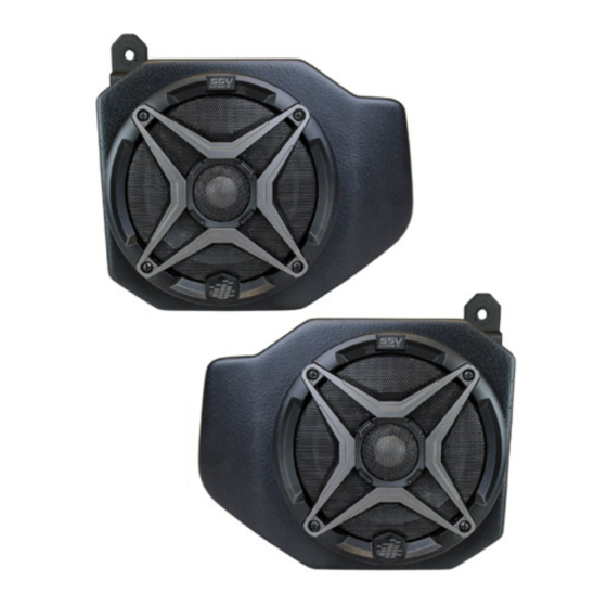
1. RG4-F65 Enclosures
(1 pair)
B. Use a panel tool to extract push pins circled in pink.
- T-30 Torx Driver
2. Enclosure Brackets x 4
A. Remove hood by turning locking pins and lifting up.
B
- Panel Removal Tool
3. M6 x 16mm Screws
4. M6 Washers x 8 (small)
x 10
C. With push pins extracted, lift to remove the cup holder and gauge cluster.
RG4-F65
Polaris Ranger
6.5" Speaker Front Kick Panels
Please read and understand these
!
instructions completely before
installation to avoid possible injury, or
damage to the accessory or vehicle.
- Phillips Screwdriver
4. M6 Washers x 2 (large)
A
C
Advertisement

Subscribe to Our Youtube Channel
Related Manuals for SSV Works RG4-F65


Summary of Contents for SSV Works RG4-F65
- Page 1 All SSV Works Electronics are covered by a limited 1 year warranty against installation to avoid possible injury, or defects in material or workmanship. All SSV Works Speakers are covered by a limited 1 year damage to the accessory or vehicle.
- Page 2 E. Unscrew (4) torx screws located in upper glove box and F. Extract push pins that are now exposed from removing the remove box. upper glove box. G. Extract push pins exposed from cup holder removal. H. Extract push pins exposed from gauge cluster removal. I.
-
Page 3: Wiring Instructions
SSV Works complete system “-” wiring instruction. refer to the amplifier wiring instructions for more detailed wiring information. Repeat for the other side. RG4-F65 © 2018 SSV Works, Oxnard, CA 93030 RG4-F65 Rev. B 7-23-18... - Page 6 SAFETY INFORMATION SSV Works Electronics are covered by a limited 1 year warranty against defects in material or workmanship. Labor for replacement of defective components is not covered. All SSV Works Speakers are covered by a limited 1 year warranty against defects in material or workmanship.
- Page 7 AMPLIFIER WIRING DIAGRAM BUTTON LOCATIONS AND FUNCTIONS 1. Play/Pause 12v+ Yellow Power On/Off MRB3 Mute 2. Volume Up/Down 3. Mode 4. Track Forward/Back Station Forward/Back Menu Settings Up/Down 5. LCD Display USB 1A charge input does not read USB data GENERAL OPERATIONS Signal ground (Black)
Need help?
Do you have a question about the RG4-F65 and is the answer not in the manual?
Questions and answers