
Summary of Contents for Förster-Technik VARIO smart 2.0
- Page 1 15. May 2018 Original Service Manual Automatic calf feeder Type VARIO smart 2.0 Powder TAP5-VS2-50 Program version 2.00 and higher...
-
Page 2: Table Of Contents
Table of contents Table of contents Introduction ..............7 Models . - Page 3 Table of contents 3.6.4 Connecting the Ethernet cable ........28 Installing the safety grid for the powder hopper attachment .
- Page 4 Table of contents 4.6.9 New installation........... 55 Software updates .
- Page 5 Table of contents 5.11.4 Gateway ............70 5.11.5 MultiReader .
- Page 6 Table of contents 9.1.10 Calibration............96 9.1.11 ID chip.
-
Page 7: Introduction
Introduction 1. Introduction This operating manual enables you to operate this automatic feeder machine safely as intend- • Have the end user provide you with the operating manual for the automatic feeder, the op- erating manuals of all additional equipment to be connected and the safety data sheets for cleaning agents. -
Page 8: Overview Of The Automatic Feeder
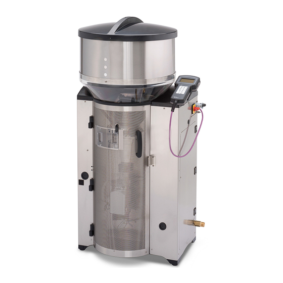
Introduction Overview of the automatic feeder 1.2.1 Front and right side view of automatic feeder 1 Milk powder container 2 Outlet valve (not shown here) 3 Milk powder discharge 4 Water supply 5 Mixer beaker 6 Rod electrode 7 Hose connection from mixer to the feeding pump 8 Mixer motor 9 Wing nut for transport restraint 10 Water connection... -
Page 9: Rear View Of Automatic Feeder
Introduction 1.2.2 Rear view of automatic feeder 1 Processor and power circuit board 2 Outlet valve for hose cleaning 1.2.3 Left side view of the automatic feeder The Name plate is located above the left side door on the outside of the automatic feeder. It contains information about the manufacturer, type and number of the automatic feeder, informa- tion about connecting the feeder to the power supply as well as its certification. - Page 10 Introduction Rear left side door 1 Cleaning agent dosing pump 2 (acid) 2 Mixer drain valve 3 Feeding box valves (optional) 4 Drain hose (not shown here) 5 Drain hose to gully 2 6 Hose connection from mixer to the feeding pump 7 Cleaning agent dosing pump 1 (alkaline) 8 Dosing device for liquid additives (optional)
-
Page 11: Boiler With Heating Circuit
Introduction 1.2.4 Boiler with heating circuit 1 Hose connection for water pipe 2 Pressure-reducing valve 3 Water meter 4 Boiler water valve 5 Boiler 6 Mixer 7 Valve unit (optional) 8 Hose connection between valve unit and teat 9 Mixer drain valve 10 Feeding pump Technical data 1.3.1... -
Page 12: Dimensions
Introduction 1.3.2 Dimensions Depth when the fly screen door is opened ~ 690mm 1.3.3 Weight Approx. 80kg. 1.3.4 Water connection Water is connected via a 3/4 inch hose and with a 3/4 inch screwed connection. NOTICE! The water must be of drinking water quality. ►... -
Page 13: Milk Powder Container
Introduction 1.3.6 Milk powder container The milk power container with attachment holds approximately 35 kg of milk substitute. 1.3.7 Number of feeding stations and animals Feeding stations: max. 4 Calves per feeding station max. 30 Calves per device max. 120 Disposal All components, liquids and solids must be disposed of in compliance with the applicable official regulations for proper waste recycling and disposal in your country. - Page 14 Introduction IFS KF Intelligent feeding station concentrate Interval feeding program Concentrate Conc. concentr. Concentration dra.v. N. Drain via teat w. entitle. With entitlement w/add. or w/addiv. With additive Manual feeding pump Milk substitute maximum Min. temp. Minimum temperature mix. full Mixer full mixer cl.
-
Page 15: Important Safety Instructions
Important safety instructions 2. Important safety instructions This chapter outlines: • The hazards caused by your automatic feeder and how to avoid them. • The safety labels attached to the automatic feeder and what they mean. • How to safely install the automatic feeder. The automatic feeder is state of the art and is produced in compliance with recognized safety regulations. - Page 16 Important safety instructions • Do not install the automatic feeder outdoors, in the open. • If there is a connection to a drinking water system, then the system must be protected from back siphoning. • The following specific hazards are associated with the automatic feeder's electrical system: •...
-
Page 17: How Am I Warned Of Hazards
Important safety instructions How am I warned of hazards? Hazards are indicated directly on the automatic feeder by safety labels (warning signs, instruc- tion and prohibition notices), and in the operating manual by specially marked hazard descrip- tions. The warnings for hazards that can cause death or injury to people are emphasized more than those for material damage, for example through the colors, hazard words or symbols used. -
Page 18: Material Damage
Important safety instructions 2.4.3 Material damage NOTICE! The word NOTICE indicates possible material damage. The automatic feeder or an object in its vicinity may be damaged, for example a calf. Prohibition notice on the automatic feeder: a pictogram crossed out in red in a white circle with a red border indicates something you are not allowed to do. - Page 19 Important safety instructions Burning/scalding Health hazards caused by additives and cleaning agents Automatic startup No spraying Grounding symbol...
-
Page 20: Safety Devices
Important safety instructions Safety devices The automatic feeder may only be operated if the safety equipment is complete and intact. The automatic feeder has the following safety equipment: • Safety signs (warning signs, instruction and prohibition signs). • The heater's safety temperature limiter. This shuts down the heater in the event of overheat- ing (temperature rises above 70°C). -
Page 21: Structural Alterations
Important safety instructions 1 Protective grid WARNING! There is a risk of injury due to rotating tools. The safety grid must always be installed when the unit is operating. Scraper next to the milk powder outlet The powder discharge opening may only be cleaned with the scraper. This prevents finger and hand injuries caused by the mixer starting up automatically. -
Page 22: Commissioning
Commissioning 3. Commissioning Have the end user provide you with the operating manual of the automatic feeder, the separate operating manuals of additional equipment to be connected as well as the safety data sheets for the cleaning agents. The appendix contains a checklist with all points you have to observe during commissioning or recommissioning (see 10.1 "Checklist for commissioning and recommissioning"... -
Page 23: Electrical Connection Provided By The Customer
Commissioning Electrical connection provided by the customer The automatic feeder needs its own power supply. • The power supply must meet the voltage and frequency specifications. The mains supply must correspond to the supply voltage stated on the left side of the automatic feeder. •... -
Page 24: Water Connection
Commissioning Water connection 1 Water connection • When connecting the automatic feeder, observe the national regulations about protection of drinking water. • Inform the end user that the supplied water must be of drinking water quality. NOTICE! Please bear in mind that high calcium, iron and manganese concentrations can cause premature wear of the components. -
Page 25: Installing Stand Partitions
Commissioning 10-15 cm 50-80 cm NOTICE! The suction hose must not be longer than 2 meters Otherwise, the calves will have problems sucking in the feed. This can lead to malnutrition. Mal- nutrition can cause impaired growth and development, increased susceptibility to illness or even death of the calves. -
Page 26: Connecting The Antennas
Commissioning WARNING! Risk of injury and death! During assembly, make sure that all supplied electrical components are assembled outside the animal area, otherwise they could be damaged. Neglect of this can lead to significant material damage as well as serious injuries to animals and humans or even death. 1. -
Page 27: Squelch Values And Identification Ranges
Commissioning 3.6.2 Squelch values and identification ranges The approximate range of the antennas is 15-25 cm. The version of the antenna is crucial for the identification range. With Nedap micro-identifica- tion, you can set the range via the squelch value. The squelch values and the identification ranges for the various identification systems are listed in the following table. -
Page 28: Connecting The Ethernet Cable
Commissioning 3.6.4 Connecting the Ethernet cable Connect the Ethernet cable as follows: 1. Remove the dummy plug on the feeder housing. 1 Dummy plug 2. Open the left side door of the automatic feeder. 3. Remove the cylinder with the Ethernet connection from the bracket on the feeder housing. 1 Cylinder with Ethernet connection 4. -
Page 29: Installing The Safety Grid For The Powder Hopper Attachment
Commissioning 1 Socket 2 Ethernet cable of automatic feeder 8. Place the unattached seal and the screw connection around the unattached Ethernet cable and connect the end to the socket. 1 Screw connection 2 Ethernet cable 3 Screw connection 4 Seal 9. -
Page 30: Switching On The Vapor Barrier For Powder Discharge
Commissioning Switching on the vapor barrier for powder discharge DANGER! Danger of death by electric shock. The electrical components of the automatic feeder are live. Switching the unit off using the main switch does not disconnect the voltage to the unit. ►... -
Page 31: Installing External Cleaning Agent Supply Pipework (Optional)
Commissioning 3.10 Installing external cleaning agent supply pipework (optional) The automatic feeder can be equipped with an external cleaning agent supply pipe. Be sure to comply with the manufacturer's instructions and national regulations for the handling, use, storage and place of installation of the cleaning agent being used. WARNING! Beware of chemical burns from the cleaning agents used. - Page 32 Commissioning 5. Connect the sealing cap to the elbow coupling and secure this once again to the cleaning agent lance. 6. Connect the cable of the cleaning agent lance to the cable tail (5th or 6th socket counting from the top) on the left hand side of the automatic feeder. 7.
-
Page 33: Switching On The Automatic Feeder
Commissioning 3.11 Switching on the automatic feeder Insert the mains plug and switch the automatic feeder on again using the Main switch . Use the hand terminal to control the automatic feeder. Note: After the hand terminal has been switched on, the version of the hand terminal's program first briefly appears in the display, before the automatic feeder carries out a test routine. -
Page 34: Setup Settings
Commissioning 3.15 Setup settings Check the settings in the Setup menu for correctness and if necessary activate the additional equipment (see 5. "Setup" - 59). 3.16 Adjusting the calibration scales If the automatic feeder is equipped with calibration scales (optional), adjust these in the Setup menu (see 5.8 "Calibration scales"... -
Page 35: Drain Time Station Parameters
Commissioning • Set the parameters for the procedure for discharging the mixer and for the overrun (see 4.6.3.5 "Mixer draining" - 48). 3.19 Drain time station parameters In the Feed menu, you can define the drink-out time for each feed station. The drain time starts when the rod electrode becomes free for the last portion and ends when the feeding box valve concerned closes (see 4.6.4 "Drain time station parameters"... -
Page 36: Cleaning
Commissioning 3.25 Cleaning For hygienic reasons, you must completely remove any coolant and lubricant remnants from the system before commissioning. To do this, execute the cleaning cycle. (see the Cleaning > Cleaning cycle chapter in the operating manual for the automatic feeder). WARNING! Beware of chemical burns from cleaning agents. -
Page 37: Programming And Control
Programming and control 4. Programming and control You control the automatic feeder using the hand terminal. The hand terminal is directly connect- ed to the automatic feeder by a cable. You switch it on and off together with the automatic feed- er. -
Page 38: The Keypad
Programming and control 1 Keypad 2 Auto LED 3 Display 4.1.1 The keypad With this key you open the Animal control menu or enter the number 1. With this key you open the Main menu or enter the number 2. With this key you open the Manual functions menu or enter the number 3. - Page 39 Programming and control With this key you open the Animal list or enter the number 5. This key is a freely selectable function key. With this key, you can enter the number 6. With this key you activate the Feeding pump or enter the number 7. This key is assigned 2 functions: •...
-
Page 40: The Auto Led
Programming and control 4.1.2 The Auto LED The LED (light-emitting diode) of the hand terminal displays important information about the sta- tus of the automatic feeder: • In automatic mode, the LED lights up green. • In offline mode, the LED is not lit up. •... -
Page 41: Symbols
Programming and control Experience shows that the lists the end user will need most often are for instance Animal control , Main menu and Manual functions which he can access directly at the touch of a key. Experience shows that the Animal list is the list that end users require most often. The animal list can be directly accessed by pressing the key . - Page 42 Programming and control 4.4.1.5 Animal identification and feed consumption The antenna symbol after a station number, such as TR1 for feeding box 1, indicates that a calf is identified at this station. A check mark after the antenna symbol means that calf identified at this station may consume feed here.
-
Page 43: Menus
Programming and control Choose • Scroll through a list, for example through the calibration menu. At the end of the list, the mes- sage "end of the list" will appear in the display. • When you enter numbers, switch between whole numbers, for example from 1 to 2 to 3. •... -
Page 44: Main Menu
Programming and control • all. You will see a list of all calves. • Total consumption. Several lists are displayed with the consumption amounts of all calves, individual calves and individual groups. • Press (optional). Here you can print out the alarm list and the feed list. 4.5.2 Main menu You can choose... - Page 45 Programming and control 4.6.1.1 Rationed mode / ad lib mode The automatic feeder operates in rationed mode by default, but can also be switched to ad lib mode. • In rationed mode, the feeder uses animal identification, i.e., the animals are individually fed rationed amounts.
-
Page 46: Checking And Setting Time/Date
Programming and control Note: These settings are used during the preparation of all feed portions. 4.6.2 Checking and setting time/date During commissioning, you have to check and, if necessary, correct the time and the date. Set the time of day, date and date format as follows: 1. - Page 47 Programming and control Enter Min. Temp. 0 in order to disable the minimum temperature parameter. 4. After entering the temperature, check that the portion is being prepared with the set tem- perature. Set temperature Minimum temperature Default value: 42ºC 39ºC Permitted range of values: 10ºC to 44ºC 0ºC to set temperature minus 0.5ºC Note: The values that you have entered for set and minimum temperature will be converted to...
- Page 48 Programming and control 4.6.3.4 Tolerance values for the concentration If the SynchroFeed functionality (optional) of the feeder is used, then the animals all drink at the same time in the boxes, which are supplied in parallel, from the portion mixed in the mixer beaker of the feeder.
-
Page 49: Drain Time Station Parameters
Programming and control Note: The mixer drain valve is included as standard. Proceed as follows to specify the amount of time after which a remaining portion in the mixer will be pumped out 1. Navigate via > Device data to the Portion sub-menu. 2. -
Page 50: Function Keys
Programming and control Default value: 16 sec. Permitted range of values: 10 to 60 sec 4.6.5 Function keys The hand terminal has two freely programmable function keys . You define which functionality or which menu will be called up when the respective function key is pressed. You define the function keys as follows: 1. - Page 51 Programming and control Here is how you define which parameters are displayed in the two columns of the animal list: 1. Navigate via > Device data to the Animal list sub-menu. 2. In Column 1 or Column 2, select by choosing which parameter is displayed in the respective column.
-
Page 52: Backing Up And Restoring Data
Programming and control • For example: The calf shown with the number 799 is in the weaning phase (reduced plan tendency), has been assigned to group A and has visited feeding box 2. At present, the calf has only called up 29% of its feed entitlement, yesterday it was only 56%. The current value for drinking speed is 100% (... - Page 53 Programming and control Restoring data This is how to perform data restoration: 1. Navigate via > Device data > Data backup to the Internal (automatic feeder) sub- menu. 2. Confirm Restore? by choosing 3. Confirm the security prompt Restore last backup? by choosing A progress bar informs you about the current status of the data restoration being carried out.
-
Page 54: Cloud
Programming and control This is how to perform data restoration: 1. Navigate via > Device data > Data backup to the SD card sub-menu. 2. Confirm Restore? by choosing to perform a backup. 2.1. If required, enter the date from which you would like to restore the data into the Date menu, and confirm this with 3. -
Page 55: New Installation
Programming and control 6.1. none. There are no errors present. 6.2. no eth. cable. No Ethernet cable is plugged in. 6.3. no Internet. There is no Internet connection available. 6.4. connect.error. There is a connection error to the server. 7. File Transfer is only for the manufacturer. 4.6.9 New installation The program (software) must be completely reinstalled (reset) when commissioning or recom-... -
Page 56: Software Updates
Programming and control The message Reinstallation completed! will appear 5. Confirm Reinstallation completed! by choosing You are back in the Reinstallation menu. Note: The settings in the feeder setup are not changed by Reinstallation. 4.6.9.3 In the event of a fault If the data are corrupted and the automatic feeder no longer boots up or no longer boots up cor- rectly, for instance when the feeder continually reboots, there is a facility to recreate the avail- able data. -
Page 57: Software Update Via Cloud
Programming and control The device will start the update procedure automatically. Wait a few minutes, and press no further keys during this time. 8. Once you see the message update successful on the display, the automatic feeder has been updated. Press , to continue. -
Page 58: Software Update Via Internal (Automatic)
Programming and control 4.3. If there is a version available for the peripheral devices, the message Peripherals update available... will appear Press <Enter> to download and install the new firmware!. Confirm with , to start the download. 4.4. Once the download has been completed, the message Download completed will appear. -
Page 59: Setup
Setup 5. Setup The program menus in the setup menu contain basic settings, e.g. for the equipment of the au- tomatic feeder. Check to ensure that the settings are correct. You open the setup menu as follows: 1. Press and keep this key pressed when you switch on the feeder. After a short time, the Setup menu will appear in the display. -
Page 60: Overview Of The Setup Menus
Setup Overview of the Setup menus Language German Time/date Time / date Type Powder Number 1 - 99 (= machine number, decimal) Address 2-FC (= CAN address, hexadecimal) System Interval (IV) Machine Operating mode Base size 500 ml Heating system electronic Boiler valve Brass... - Page 61 Setup CR water heating system <IFS concentrate feeder 1 .. 8> Concentrate Allocation: [C-station 1 .. 8] Address: 51 - 60 Type: Standard Animal scales Activate Adjust Address 1-FC (= CAN address, hexadecimal) Contrast Terminal Sleep mode 0 - 999 min Printer no / serial / CAN M-ECN:...
-
Page 62: Language
Setup Initial installation: Date last: Date Service Type: RS1 / RS2 / RS3 next: Date Type: RS1 / RS2 / RS3 Service done? Language You select the language for the user interface of the feeder as follows: 1. In the setup menu, choose the Language option. 2. -
Page 63: Automatic Feeder Address
Setup Note: When connecting more than one automatic feeder, be sure that each number is only as- signed once. You select the feeder number as follows: 1. In the setup menu, choose the Machine option. 2. In Number, you select a number. 3. -
Page 64: Heating System
Setup 5.4.6 Heating system Here you specify whether the feeder has a heating system and, if so, what type of heating relay it has. You set the heating type as follows: 1. In the setup menu, choose the Machine option. 2. -
Page 65: Flushing Agent 2
Setup This is how to activate flushing agent 1: 1. In the setup menu, open the Equipment menu item. 2. In the Flushing agent 1 menu, choose yes if there is a flushing agent pump for flushing agent 1 (alkaline) fitted, otherwise choose no. 3. -
Page 66: Air Valve
Setup 3. Confirm your entry with 5.5.9 Air valve The air valve is part of the compressed air cleaning system. 5.5.10 Mixer temperature sensor The temperature sensor in the mixer continually records the temperature of the feed in the mixer beaker. -
Page 67: Id Chip
Setup ID chip Before delivery, the ID chip is configured with the Setup settings for the automatic feeder. These are saved in non-editable form. This means you can restore the original settings of the setup at any time. For example, this may be necessary if you have accidentally changed a setting or the processor board has to be replaced. -
Page 68: Stations
Setup Stations Activate the feed or concentrate station and define the additional equipment for these stations or any additional equipment in the Stations menu. 5.9.1 Feed You set the feeding box as follows: 1. In the setup menu, choose the Stations > Feed > Internal option. 2. -
Page 69: Communication
Setup 3. Confirm your entry with 5.11 Communication 5.11.1 Printer Current animal lists can be generated via the automatic feeder’s printer function. • Serial: Select this option if you have connected a printer to the automatic feeder via the se- rial interface. -
Page 70: Gateway
Setup 4. In Finish? you break off the connection to the cloud and therefore stop data transfer. 5. In Status, you can see the current status of the connection to the cloud. The possible sta- tuses are online, offline or reconnecting. 6. -
Page 71: Calibration
Calibration 6. Calibration The first calibration is performed by your service technician during commissioning. You must manually recalibrate powder and liquid feed and cleaning agents because the actual quantity will deviate from the set quantity for various reasons, such as fluctuations in water pres- sure. -
Page 72: Calibrating With Calibration Scales
Calibration 2.8. Tilt the mixer so that the water flows into the graduated cylinder. Measure the collect- ed water in milliliters. 2.9. In the Actual menu, enter this measured quantity using the number keys. 2.10. Confirm with 2.11. Date now shows the current date. 2.12. - Page 73 Calibration 2.4. Date shows when the water was last calibrated. 2.5. Confirm Start? by choosing . The calibration procedure will start. The set value of 500 ml will be shown first in the display. 2.6. Confirm Exit automatic mode? by choosing .
- Page 74 Calibration 2.2. Set qty shows the quantity of cleaning agent to be dispensed by the automatic feed- 2.3. Runtime shows the time in which the automatic feeder should dispense the cleaning agent. 2.4. Date shows when the cleaning agent was last calibrated. 2.5.
-
Page 75: Transmitter And Animal Management
Transmitter and animal management 7. Transmitter and animal management All menus for management of the list of all transmitters and the calves registered at the feeder can be found via > Animal management. Managing the transmitters 7.1.1 Basics 7.1.1.1 Identification process at the station 1 Antenna 2 Collar transmitter 3 Earmark transmitter... -
Page 76: Reading Transmitter Numbers
Transmitter and animal management 7.1.3 Reading transmitter numbers When creating new transmitter numbers, it is a good idea to have these read by the feeder. This saves you from typing in the numbers and eliminates the possibility of typing errors. You read transmitter numbers in the automatic feeder as follows: 1. -
Page 77: Editing Transmitters Or Animal Numbers
Transmitter and animal management 7.1.5.1 Consecutive assignment of animal numbers There is a counter which counts up for each new transmitter number as it is read. In this way, all of the transmitter numbers that are registered by the identification function are linked to con- secutive animal numbers;... -
Page 78: Deleting The Transmitter Number When Canceling An Animal
Transmitter and animal management Reading the new transmitter number for the change You read a new transmitter number as follows: 1. Navigate via > Animal management > Transmitters to the Edit sub-menu. 2. Select the transmitter number to be changed. 3. -
Page 79: Calling Up The Transmitter Statistics
Transmitter and animal management 7.1.8 Calling up the transmitter statistics You call up a transmitter statistic as follows: 1. Navigate via > Animal management > Transmitters to the Information sub-menu. 2. An overview of the transmitters created in the system is displayed. 2.1. -
Page 80: Automatically Registering Animals
Transmitter and animal management 7.2.2 Automatically registering animals If an animal that is not yet registered enters the feeding station for the first time, it can then be automatically registered. For automatic registration, three different modes can be set which are described in detail in the following three sub-sections. -
Page 81: Canceling Animals Or Animal Groups
Transmitter and animal management 7.2.2.3 Creating transmitter numbers and automatically registering calves To shorten the registration process even more, you can specify that calves can also be regis- tered if their transmitter numbers are not known in the system. This eliminates the need for read- ing or manual entry of transmitter numbers. -
Page 82: Canceling A Group
Transmitter and animal management 7.3.2 Canceling a group You can cancel a group registration as follows: 1. Navigate via > Animal management > Cancellation to the Group sub-menu. 2. Select the required group. 3. In the Registered menu you can see how many calves are being fed according to the cor- responding plan. -
Page 83: Shutdown And Recommissioning
Shutdown and recommissioning 8. Shutdown and recommissioning This chapter explains how to shut down the automatic feeder temporarily or permanently and recommission it. Shutdown You can shut down the automatic feeder temporarily or permanently. To make the procedure easier and ensure that you do not miss any steps, see the check list Shutting down the automatic feeder in the appendix (see 10.3 "Shutdown checklist"... - Page 84 Shutdown and recommissioning 1. Start the maximum number of cleaning programs (see Cleaning chapter in the operating manual for the automatic feeder). 2. Take the cleaning agent lance off the cleaning agent container, flush it out with water and place it in a bucket full of water 2.1.
- Page 85 Shutdown and recommissioning 8. Dispose of the water hose. NOTICE! Beware of the risk of infection. To prevent infections, use a new hose when recommissioning the unit. 9. Remove the teat from the feeding box. 10. Dispose of the teat. NOTICE! Beware of the risk of infection.
-
Page 86: Permanent Shutdown
Shutdown and recommissioning NOTICE! Pressure washers can damage the automatic feeder. ► Only clean the automatic feeder by hand using a damp cloth. 17. Empty the powder container. 18. Remove the screws holding the safety grid on the powder container. Remove the safety grid. 19. -
Page 87: Recommissioning
Shutdown and recommissioning Recommissioning 8.2.1 Recommissioning after temporary shutdown Proceed as follows to recommission the automatic feeder: 1. Remove the protective covers from the automatic feeder. 2. Clean the outside of the automatic feeder with a damp cloth. 3. Install the safety grid for the powder hopper attachment. Screw the screws back into the holes provided. -
Page 88: Recommissioning After Processor Card Replacement
Shutdown and recommissioning 10. Connect the Ethernet cable. 11. Remove the locks on the antenna connections and connect them to the antennas. 12. Plug the power plug into the power outlet. 13. Switch the automatic feeder on using the Main switch . Fault, Boiler not filled will appear in the display of the hand terminal. - Page 89 Shutdown and recommissioning If no data are present, follow the same steps as in commissioning (see 3. "Commissioning" - 22). 4. Read the ID chip and check the setup settings (see 5. "Setup" - 59). 5. In the Basic settings menu, enter the desired language, the current date and the current time of day.
-
Page 90: Faults And Warnings
Faults and warnings 9. Faults and warnings The automatic feeder shows fault messages or warning messages on the display to indicate faults during feeder operation. In the event of a fault, automatic mode is interrupted and no feed is prepared. NOTICE! An interruption in feeding operation means that your calves will not receive any feed. -
Page 91: Temperature Too High
Faults and warnings 2. Check that the heater is working properly. 9.1.3 Temperature too high If the water temperature in the boiler is too high, Fault, temperature too high will appear in the display. Feeder operation will be interrupted until the water in the boiler has cooled to the set maximum temperature. - Page 92 Faults and warnings Feeder operation will be interrupted. Make sure that the end user provides the calves with feed using an alternative method as long as feed operation is interrupted. You can correct the fault as follows: 1. Confirm Fault, water shortage by choosing 2.
-
Page 93: Water Meter
Faults and warnings 9.1.6 Water meter If the rod electrode is grounded when water is dispensed but the water meter sends out no pulse, Fault, water meter will appear in the display. Feeder operation can be continued in emergency mode. You start emergency mode as follows: 1. -
Page 94: Heating System
Faults and warnings You can correct the fault as follows: 1. Switch the automatic feeder off using the Main switch and disconnect the mains plug. 2. Check all components carrying feed from the mixer to the mixer drain valve or from the mixer up to the teat for clogs and remove them. -
Page 95: Boiler Temperature Sensor
Faults and warnings You can correct the fault as follows: • Check whether safety temperature limiter has been triggered. • Check the setup settings for the heating system. • Setup > Machine > Heating: electronic • Check the temperature sensor. If the temperature sensor is defective, replace it. -
Page 96: Calibration
Faults and warnings You can correct the fault as follows: 1. Switch the automatic feeder off using the Main switch and disconnect the mains plug. 2. Remove the metal cover on the back of the automatic feeder. 3. Measure the resistance of the temperature sensor on the main board. 4. -
Page 97: Station/Drain Valve
Faults and warnings You replace the ID chip as follows: 1. Switch the automatic feeder off using the main switch and disconnect the power plug. 2. Open the flap on the back of the automatic feeder. 3. Disconnect the old ID chip from the main board (see circuit diagram provided). 4. -
Page 98: Uncontrolled Output
Faults and warnings 9.1.13 Uncontrolled output The automatic feeder monitors all outputs during current operation which are responsible for the dispensing of water, milk, milk powder, additives and flushing agent as well as the mixer drain valve. If the corresponding relays are actuated for more than 60 seconds, Fault, uncontrolled output will appear in the display. -
Page 99: Warnings
Faults and warnings Warnings 9.2.1 Emptying the mixer If the mixer cannot be emptied, the message Warning, draining the mixer will appear. For ex- ample, this can be because the drain is clogged or the feeding pump is no longer running. DANGER! Fatal electric shock. -
Page 100: Mixer Temperature Sensor
Faults and warnings 9.2.2 Mixer temperature sensor If the temperature sensor in the mixer beaker is faulty or the temperature of the mixed feed in the mixer beaker drops below 0°C, the Mixer temp. sensor warning will appear in the display. You rectify the warning as follows: 1. -
Page 101: Unknown Transmitter
Faults and warnings 3. Assign another address which is still available to the CAN node with the duplicate address. For more information on assigning CAN addresses, see the Setup > Address chapter (see 5.4.3 "Automatic feeder address" - 63). Note: If possible, use an address from the standard range of numbers for the CAN partici- pant concerned. -
Page 102: Fill Up The Mp Container
Faults and warnings 9.2.8 Fill up the MP container If the automatic feeder is equipped with a powder sensor, this will output a warning if the MP in the container is lower than the sensor. If the sensor reports container empty for 10 portions in succession, Warning, top up MP will appear in the display. -
Page 103: Duplicate Animal Number
Faults and warnings NOTICE! An interruption in feeding operation means that your calves will not receive any feed. This can lead to malnutrition. Malnutrition can cause impaired growth and development, in- creased susceptibility to illness or even death of the calves. ►... -
Page 104: Machine Capacity
Faults and warnings 5. Once you have changed the animal number, confirm confirm? by choosing Note: Only when you have changed the animal number will your confirmation take effect and the warning be deleted. 9.2.12 Machine capacity When there is no more storage space available for animal numbers or transmitter numbers, the Warning, Machine capacity will appear. -
Page 105: Other Faults And Messages
Faults and warnings Other faults and messages 9.3.1 Automatic feeder 9.3.1.1 Starting program The message Smart Vxx.xx starting program appears when the control program of the auto- matic feeder starts. Wait until the automatic feeder is ready to operate. 9.3.1.2 Initialization of the feeder The message first startup Press enter to start installation will appear in the display in the following cases:... -
Page 106: Boot Loader
Faults and warnings 9.3.2.3 Waiting The following faults prevent the hand terminal from initializing: • The CAN bus address of the terminal is not the same as the one defined in setup of the of the automatic feeder. • The feeder control unit is not active. The message terminal Vxx.xx waiting appears. -
Page 107: Service Messages
Faults and warnings Service messages A service message will appear in the automatic feeder's display every four months. This mes- sage indicates the maintenance (regular service) that must be performed. Compliance with these maintenance intervals is the only way to ensure the long life and reliability of the automatic feeder. -
Page 108: Diagnosis
Faults and warnings Diagnosis The Diagnostics menu helps you to find faults in the event of technical problems. You can reach this menu via . A diagnosis can be performed for the following parts of the automatic feeder: • Valves •... -
Page 109: Checking The Heating
Faults and warnings 9.5.1.2 Motors Check the motors as follows: 1. Navigate via > Diagnostics to switch to the Motors sub-menu. 2. Confirm Mixer: start? by choosing , to start the mixer. 3. Confirm Powder start? by choosing , to start the powder conveyor. 4. -
Page 110: Checking Sensors
Faults and warnings 9.5.3 Checking sensors In this menu, you check the sensors of the following components: • Point and rod electrode. • Button for the manual feeding pump (active/inactive). • Mixer and boiler (temperatures of the liquids in the boiler and in the mixer beaker). •... -
Page 111: Calibration Scales
Faults and warnings 9.5.4 Calibration scales In this menu, you check the calibration scales. Check the calibration scales as follows: 1. Navigate via > Diagnostics to switch to the Calibration scales sub-menu. 2. Confirm check? by choosing , to check the calibration scales. 3. - Page 112 Faults and warnings • How often the automatic feeder received no response from the identification system. • How often the minimum temperature in the heat exchanger was not met (heating). • How often the water test was negative (water shortage). •...
-
Page 113: Version
Faults and warnings 9.5.7 Version In the Version menu, you can check version numbers. The following units have a version num- ber: • Feeder • Processor • ID chip • Terminal • Identifications at existing feeding stations. • Peripheral device Check the version as follows: 1. -
Page 114: 10. Appendix
Appendix 10. Appendix Note: The following checklists and overviews also include additional equipment. If this equip- ment is not fitted in your specific case, skip the irrelevant items on the list. 10.1 Checklist for commissioning and recommissioning Note: Before each initial startup or restart of the automatic feeder, you must carefully read and observe the operating manual, particularly the safety information. - Page 115 Appendix Connect power supply. Switch on automatic feeder. Fill boiler with water. Reinstall device data. Setup Switch the automatic feeder off and again at main switch whilst holding down Check the following settings: Language: Check time/date, set if necessary. Machine: Assign number and address.
- Page 116 Appendix Configure single IFS feeding box(es) / set extras, if any. For IFS feeding box(es), assign CAN bus addresses: To do this, put IFS (feeding box) into search mode and then, via search? assign the address. Configure quadruple IFS feeding box(es) and issue CAN bus addresses: To do this, put compact IFS unit into search mode and then allocate address via search? assign the address.
- Page 117 Appendix CalfProtect (open after xx min). Calibration Boiler water Additive 1/2 Flushing agent Concentrate stations Hose pumps Settings for automatic calibration of MP/water. Settings for automatic calibration of the hose pump. Registration Antenna test Set the scheme for the transmitter number assignment: consecutive, automatic. Reading transmitter numbers.
- Page 118 Appendix Change date of individual animals Group Feed Concentration Concentrate Additive 1 / additive 2 Weight Plan day (correction days) Cleaning Check or make settings: Temperature, flushing water. Flushing agent amount. Flush the teats: Drainage mode Cleaning circuit Air (pulsating compressed air cleaning) Perform cleaning.
-
Page 119: Materials List
Appendix and confirm Boiler: fill by choosing Input the time and date using > Device data > Date and Time. Run cleaning programs. Fill milk powder (MP). Perform calibration. Check setup settings. 10.2 Materials list The materials used in the automatic feeder include: •... -
Page 120: Shutdown Checklist
Appendix 10.3 Shutdown checklist Shutdown Perform flushing. Stop the cleaning agent supply and drain the cleaning agent from the system. Drain water from boiler, solenoid valves, pressure valve, and volume control valve. 1) Close water tap. 2) On the hand terminal choose >... -
Page 121: Standard Feeding Plans
Appendix 10.4 Standard feeding plans... - Page 122 Appendix...
-
Page 123: Can Bus Addresses
Appendix 10.5 CAN bus addresses Standard addresses The following chart shows an example of address assignment based on default values. On the following page, you can assign completely customized addresses. Copy the template if needed. Note: You can assign a number only once. Note: If possible, do not change the standard addresses. - Page 124 Appendix Template for custom address assignment Default addresses 01 - 10: Hand terminal Adress..11 - 20: Automatic feeder(s) 21 - 30: Scale(s) 41 - 50: IFS F-station(s) 51 - 60: IFS C-station(s) Adress..61 - 70: IFS F-station(s) quadr. 71 - 79: CalfRail Adress..
-
Page 125: Checking Components For Compliance With National Regulations
Appendix 10.6 Checking components for compliance with national regula- tions All electrical components must be checked regularly for electrical safety in accordance with the intervals and test methods defined in the national regulations. If any faults or damage are detected during the inspection, the faulty components have to be replaced before the automatic feeder can be used again. -
Page 126: Index
Index Index cleaning agent supply pipe 31 Cloud 42 Ad lib mode 45 Communication Alarm 42 Cloud 69 Angle brackets 41 Gateway 70 Animal control 43 MultiReader 70 Animal list 35 39 50 Network 69 Arrows 41 Printer 69 Auto LED 40 Restart 70 Automatic feeder address 63 Automatic feeder number 62... - Page 127 Index Air valve 66 Circulation valve 65 ID chip 67 Flushing agent 1 64 Identification 27 66 Flushing agent 2 65 65 Identification range 27 Flushing agent sensor 65 Initial start-up Mixer drain valve 64 Calibration 71 Mixer temperature sensor 66 Connecting antenna cables 27 Point electrode 66 Connecting the Ethernet cable 28...
- Page 128 Index Temporary shutdown 83 Sleep mode 42 Plan tendency 42 Software update 56 Potential equalization 23 Square brackets 41 Powder sensor 65 Squelch 66 Prohibitory signs 18 Squelch values 27 Pushbutton 25 Stations 68 Switching on the automatic feeder 33 Rationed mode 45 Symbols 41 Rear view of automatic feeder 9...
- Page 129 Index Unknown transmitter 101 Water connection 12 Water pressure 24 Weight 12...
- Page 130 EC declaration of conformity according to the EU Machinery Directive 2006/42/EG, Annex II, 1.A Manufacturer: Förster-Technik GmbH, Gerwigstr. 25 78234 Engen Person residing within the Community authorised to compile the relevant technical documentation: Müller Barbara Förster-Technik GmbH, Gerwigstr. 25 78234 Engen Description and identification of the machinery: Make: Automatic feeder...
Need help?
Do you have a question about the VARIO smart 2.0 and is the answer not in the manual?
Questions and answers