Table of Contents
Advertisement
Quick Links
Advertisement
Table of Contents

Related Manuals for Trinamic PANdrive PD-1141


Summary of Contents for Trinamic PANdrive PD-1141
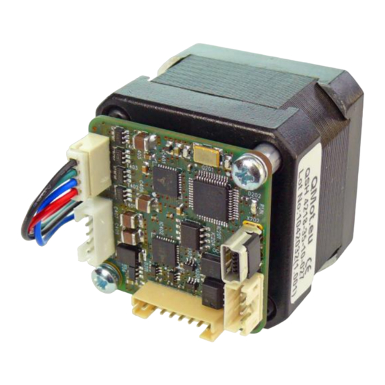
- Page 1 MECHATRONIC DRIVE WITH STEPPER MOTOR PANdrive Hardware Version V1.2 HARDWARE MANUAL PD-1141 Stepper Motor with Controller / Driver 0.27 - 0.49 Nm / 24 V DC USB, RS485, and S/D Interface NIQUE EATURES TRINAMIC Motion Control GmbH & Co. KG Hamburg, Germany www.trinamic.com...
-
Page 2: Table Of Contents
PD-1141 Operational Description ........................... 22 Calculation: Velocity and Acceleration vs. Microstep and Fullstep Frequency ........ 22 10 Life Support Policy ..............................24 11 Revision History ................................25 11.1 Document Revision ............................25 11.2 Hardware Revision ............................25 12 References ..................................25 www.trinamic.com... -
Page 3: Features
Electrical and mechanical data Supply voltage: +24 V DC nominal (9… 28 V DC) Motor current: up to 1.1 A RMS / 1.7 A peak (programmable) 0.27… 0.49 Nm max. holding torque (depends on motor) Refer to separate TMCL Firmware Manual, too. www.trinamic.com... - Page 4 PD-1141 Hardware Manual (Rev. 1.04 / 2013-JUL-23) TRINAMIC – E TMCL NIQUE EATURES ASY TO SE WITH stallGuard2™ stallGuard2 is a high-precision sensorless load measurement using the back EMF on the coils. It can be used for stall detection as well as other uses at loads below those which stall the motor.
-
Page 5: Order Codes
1x cable loom for power and RS485 connector (length 200mm) 1x cable loom for multipurpose I/O connector (length 200mm) 1x cable loom for S/D connector (length 200mm) 1x USB type A connector to mini-USB type B connector cable (length 1.5m) Table 2.2 Cable loom order codes www.trinamic.com... -
Page 6: Mechanical And Electrical Interfacing
24±1 22-0.05 42±1 Model Length of motor PD42-1-1141 ±1 mm 33.5 PD42-2-1141 ±1 mm Length 13 max PD42-3-1141 ±1 mm 2xM3 42±1 42±1 42±1 42±1 FRONT VIEW REAR VIEW Figure 3.1 PD-1141 dimensions www.trinamic.com... -
Page 7: Stepper Motor Specifications
Axis Length (typ.) Axis D-cut (0.5mm depth) Maximum Radial Force (20 mm from front flange) Maximum Axial Force Ambient temperature °C -20…+50 -20…+50 -20…+50 Related PANdrive PD42-1-1141 PD42-2-1141 PD42-3-1141 Table 3.1 NEMA 17 / 42mm stepper motor technical data www.trinamic.com... -
Page 8: Connectors Of Pd-1141
CVIlux CI01 series, 4 pins, 2mm pitch Connector housing JST: PHR-4 Contacts JST: SPH-002T-P0.5S Wire: 0.22mm Mini-USB Molex 500075-1517 Any standard mini-USB plug Connector Mini USB Type B vertical receptacle Table 3.1 Connectors and mating connectors, contacts and applicable wire www.trinamic.com... -
Page 9: Power And Rs485 Connector
Please see also chapter 6 (operating values). There is no reverse polarity protection! The module will short any reversed supply voltage due to internal diodes of the driver transistors. www.trinamic.com... -
Page 10: Rs485
PCs already include these additional resistors (e.g. USB-2-485). Slave Slave node node n - 1 pull-up (1k) RS485+ / RS485A termination resistor (120 Ohm) RS485- / RS485B pull-down (1k) Figure 3.4 Bus lines with resistor network www.trinamic.com... -
Page 11: Multipurpose I/O Connector
For all digital inputs (IN_1, IN_2, IN_3) a 1k pull-up resistor to +5V can be activated. Then these inputs have a default (unconnected) logic level of 1 and an external switch to GND can be connected. This might be especially interesting in case these inputs are used as stop and home switch inputs (alternate function). www.trinamic.com... -
Page 12: Digital Inputs In_0, In_1, In_2
HOME - home switch input IN_2 (8) digital input (connected to processor) Table 3.7 Multipurpose inputs / alternate functions All three digital inputs are connected to the on-board processor and can be used as general purpose digital inputs (default). www.trinamic.com... -
Page 13: Analog Input Ain_1
(relais etc.) above supply voltage (see figure below). Using free-wheeling diodes connected to VDD supply voltage: None of the two outputs should be connected to any voltage above supply voltage of the module. OUT_0, OUT_1 microcontroller Figure 3.7 General purpose outputs www.trinamic.com... -
Page 14: Step/Direction Connector
Direction / Enable signals might be driven either by open-collector / open-drain outputs or by push-pull outputs. In case of push-pull outputs the COMMON supply voltage should be equal / similar to the high signal voltage level of the push-pull drivers. +3.3V Common (5..24V) microcontroller Enable TMC262 Step TMC262 Direction Figure 3.8 Step/Dir/Enable inputs www.trinamic.com... -
Page 15: Motor Connector
Example for connecting the QSH4218 NEMA 17 / 42mm stepper motors: green TMCM-1141 QS4218 Motor Motor connector pin Cable color Coil Description Motor coil B pin 1 black Blue Motor coil B pin 2 Green Motor coil A pin 2 Black Motor coil A pin 1 www.trinamic.com... -
Page 16: Mini-Usb Connector
Please note that the module might draw current from the USB +5V bus supply even in USB self powered operation depending on the voltage level of this supply. Motor movements are not possible in this operation mode. Therefore, connect the power connector and change to USB self powered operation mode. www.trinamic.com... -
Page 17: Reset To Factory Defaults
When there is no valid firmware programmed into the board or during firmware update the green LED is permanently on. TMCL F EHAVIOR OF S WITH TANDARD IRMWARE Status Label Description Heartbeat This green LED flashes slowly during operation. Green LED Figure 5.1 On-board LED www.trinamic.com... -
Page 18: Operational Ratings
IN_H 1/2/3 Measurement range for analog input IN_0 IN_0 Table 6.2 Operational ratings of multipurpose I/Os RS485 PERATIONAL RATINGS OF INTERFACE Symbol Parameter Unit Number of nodes connected to single RS485 RS485 network Table 6.3: Operational ratings of RS485 interface www.trinamic.com... -
Page 19: Torque Curves
Figure 7.1 PD42-1-1141 torque vs. velocity 24V / 1.1 A, 256µsteps 7.1.2 PD42-2-1141 Torque Curves PD42-2-1141 - 1.1A RMS Phase Current, 256 uSteps 0,50 0,45 0,40 0,35 0,30 0,25 0,20 0,15 0,10 0,05 0,00 1000 10000 speed[rpm] Figure 7.2 PD42-2-1141 torque vs. velocity 24V / 1.1 A, 256µsteps www.trinamic.com... -
Page 20: Pd42-3-1141 Torque Curves
PD-1141 Hardware Manual (Rev. 1.04 / 2013-JUL-23) 7.1.3 PD42-3-1141 Torque Curves PD42-3-1141 - 1.1A RMS Phase Current, 256 uSteps 0,70 0,60 0,50 0,40 0,30 0,20 0,10 0,00 1000 10000 speed[rpm] Figure 7.3 PD42-3-1141 torque vs. velocity 24V / 1.1A, 256µsteps www.trinamic.com... -
Page 21: Functional Description
Remark: stop switches are an alternate function of two out of three digital inputs. The PD-1141 comes with the PC based software development environment TMCL-IDE for the Trinamic Motion Control Language (TMCM). Using predefined TMCL high level commands like move to position a rapid and fast development of motion control applications is guaranteed. -
Page 22: Pd-1141 Operational Description
The change in the pulse rate per time unit (pulse frequency change per second – the acceleration a) is given by pulse ramp This results in acceleration in fullsteps of: with af: acceleration in fullsteps usrs www.trinamic.com... - Page 23 1907 1000 ALCULATION OF THE NUMBER OF ROTATIONS A stepper motor has e.g. 72 fullsteps per rotation. 1907 fullsteps rotation 1907 1589 fullsteps rotation www.trinamic.com...
-
Page 24: Life Support Policy
PD-1141 Hardware Manual (Rev. 1.04 / 2013-JUL-23) 10 Life Support Policy TRINAMIC Motion Control GmbH & Co. KG does not authorize or warrant any of its products for use in life support systems, without the specific written consent of TRINAMIC Motion Control GmbH & Co. KG. -
Page 25: Revision History
(version 1.1 is 100% firmware compatible with V1.0) TMCM-1141_V12 2011-DEC-12 Mounting holes connected to GND Table 11.2 Hardware revision 12 References [PD-1141 TMCL] PD-1141 TMCL Firmware Manual [TMC262] TMC262 Datasheet [TMC429] TMC429 Datasheet [TMCL-IDE] TMCL-IDE User Manual [QSH4218] QSH4218 Manual Please refer to www.trinamic.com. www.trinamic.com...
Need help?
Do you have a question about the PANdrive PD-1141 and is the answer not in the manual?
Questions and answers