Table of Contents
Advertisement
Advertisement
Table of Contents

Related Manuals for FILTRABOX COMPACTX

Summary of Contents for FILTRABOX COMPACTX
- Page 1 USER MANUAL...
-
Page 3: Table Of Contents
TABLE OF CONTENTS INTRODUCTION – pg. 3 SPECIFICATIONS – pg. 4 iii. MACHINE DIAGRAM – pg. 5 MACHINE DIAGRAM: USER INTERFACE – pg. 6 MACHINE DIAGRAM: MODULES – pg. 6 ASSEMBLY INSTRUCTIONS – pg. 7 vii. INSTALLATION INSTRUCTIONS – pg. 8 viii. -
Page 4: Introduction
Modules easily extracts dust and fumes, circulating the air through the filters, outputting the clean air back into the room. Servicing and maintaining the Filtrabox is a snap. The machine is made up of modular parts, making it easy for you to swap-out and swap-in any module by... -
Page 5: Specifications
SPECIFICATIONS Compact X 120V / 240V Voltage 50 / 60 Frequency (Hz) Wattage (kW) 1x Brushless Blower Type Length 525.65 / 20.695 (mm/inches) Width 395.20 / 15.559 (mm/inches) Height 746.40 / 29.386 (mm/inches) 45/99 Weight (kg/lbs) Max Flow (CFM) 42 (High Pressure) Pressure: (in. -
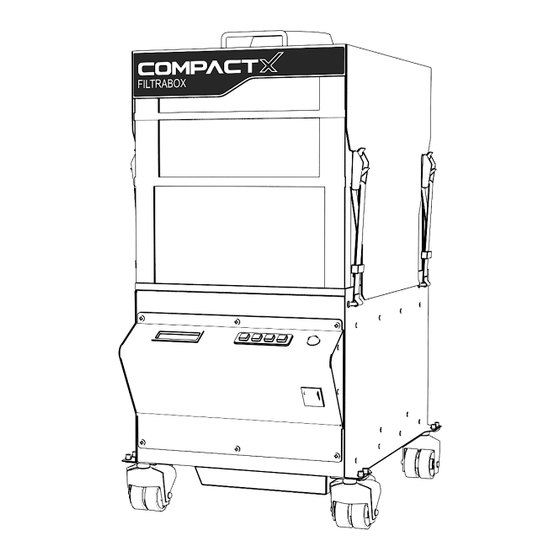
Page 6: Machine Diagram
MACHINE DIAGRAM... -
Page 7: Machine Diagram: User Interface
MACHINE DIAGRAM – USER INTERFACE MACHINE DIAGRAM – MODULES... -
Page 8: Assembly Instructions
ASSEMBLY INSTRUCTIONS UNPACKING ! Useful Tip: The Filtrabox is shipped in custom packaging for maximum protection during transport. Consider keeping the packaging should you wish to ship the product again. ! Attention: The OXY-Carbon Gas Filter is HEAVY. Each filter weighs approximately 50lbs each. -
Page 9: Installation Instructions
Engage the brakes on the two front wheels to hold the machine in place. 4. Install the supplied power cord onto the back of the Filtrabox and turn it on with the Main Power Switch located on the bottom of the User Interface. -
Page 10: Quick Start Instructions
514.840.9696 ext. 102 access to the internet by, calling 2. Turn your Filtrabox ON using the main power switch located on the front of the device. Filtrabox will request an UNLOCK code which is also known as the AUTHENTICATION CODE. -
Page 11: Calibration
Filtrabox Technical support for help. 3. If you have previously set the number of blowers and wish only to Calibrate Filtrabox to a new application, press the “Menu” button. Press the right arrow key to advance the screen until you reach the “New Application Calibration”... -
Page 12: Airflow Setting
This ensures that you are using your filters to their maximum potential which minimizes costs. ! USEFUL TIP 2: Start by setting your Filtrabox at 15% for a small sized laser or 25% for a medium sized laser, or 40% for a large sized laser and incrementally increase up from those starting points, using the 4-6 second rule to determine the minimum adequate evacuation setting. - Page 13 8. When the laser is not in use, press the “Power” button to turn the blower(s) off. 9. Filtrabox has an EZ-link feature that allows you to turn the blowers ON or OFF remotely from the laser (if this feature is available on your laser). See the EZ-LINK section of the manual.
-
Page 14: Filter Replacement Instructions
This is most likely due to airflow blockage in the pre-filter or HEPA filter from normal usage. The Filtrabox Compact and Expand systems have 3 types of filters; Pre-Filter, HEPA filter and OXY- Carbon Filter. 1. Pre-Filter FIL-P-CX-427: Collects fine dust 2. -
Page 15: "Filter Check" Feature
“CHECK FILTER” feature. 2. Press the “OK” button to initiate the “CHECK FILTER” process. 3. Filtrabox will assess the status of all the Dust Filters in your systems and then prompt you to remove the Pre-Filter. Follow the instructions on the screen. -
Page 16: Replacing The Dust Pre-Filter
! Important Note: The Filter Alignment Rings must be centered correctly into each filter. They should fit inside both filters when installed correctly. ! To avoid any risk of electrical discharge, turn off and unplug the Filtrabox before doing any activities that require disassembly of the unit. -
Page 17: Oxy-Carbon Gas Filter Replacement Procedure
514.840.9696 ext. 102 ! When laser odor becomes evident, it is time to change the GAS FILTER. ! To avoid any risk of electrical discharge, turn off and unplug the Filtrabox before doing any activities that require disassembly of the unit. -
Page 18: Blower Module Replacement
BLOWER MODULE REPLACEMENT ! To avoid any risk of electrical discharge, turn off and unplug the Filtrabox before doing any activities that require disassembly of the unit. ! Replacement modules can be purchased from your dealer or: info@filtrabox.com or call 514.840.9696 ext. 102 The Compact X comes standard with one Blower Module that can be easily replaced by removing a few screws and disconnecting/connecting two cables. -
Page 19: Electronics Module Replacement
In the event of damage or a malfunction, the entire module can be removed from Filtrabox by removing a few screws and disconnecting a few cables. Contact Filtrabox to order. 1. !IMPORTANT! Ensure that the Filtrabox is powered off and unplugged. -
Page 20: Settings
The blower(s) will be engaged to the previously set “Airflow %” 2. Link On/Off This mode uses the DB9 connection at the rear or the Filtrabox. The blowers will be engaged at the previously set “Airflow %” when Laser requests it. (If feature is available on the Laser.) When the Laser does not require any airflow, the system automatically... -
Page 21: Filter Check
While in the “New Application Calibration” setting, press the “OK” button to initiate Calibration. The Calibration process will take approximately one minute. SERVICE MENU SETTING This menu is only to be used by Filtrabox Technicians or with the guidance of a Filtrabox Technician. -
Page 22: Ez-Link Controller Set-Up And Pin-Out
EZ-LINK CONTROLLER SET-UP AND PIN-OUT COMPACT AND EXPAND DB9 PIN-OUT Start Exhaust System Pin 1 Pin 9 Check Filter Figure 1: An example of a D-Sub 9 connector COMPACT AND EXPAND Pins 4 & 5: Normally Open – Output from Laser Controller The controller connects these two pins to start the exhaust system. - Page 23 EZ-LINK Electrical Requirements Figure 2 below shows the required circuit for the output on the laser’s filter control system. When the laser’s filter control unit wishes to turn on the exhaust system, the contacts on the relay are closed, thus connecting the two output pins.
-
Page 24: Support
SUPPORT For any and all questions related to our Filtrabox products and accessories, please do contact us anytime. It will be our pleasure to make fume extraction easier and more effective for any of your applications. Please contact us through: info@filtrabox.com or call 514.840.9696 ext. 102... -
Page 25: Warranty
WARRANTY 1 Goods manufactured by PAT: PAT warrants that the Goods manufactured by it will be free from defects in materials and workmanship for a period of 12 months from the date of AUTHENTICATION. Exceptions: Spare parts including replacement filters: 1 month from installation. Used and ex-demonstration equipment: 1 month from installation.
Need help?
Do you have a question about the COMPACTX and is the answer not in the manual?
Questions and answers