
Subscribe to Our Youtube Channel
Related Manuals for Applied Physics Systems 1540


Summary of Contents for Applied Physics Systems 1540
- Page 1 MODEL 1540 FLUXGATE MAGNETOMETER USER MANUAL CONTACT US HEADQUARTERS 425 Clyde Avenue Mountain View, CA 94043 OFFICE 650.965.0500 EMAIL info@appliedphysics.com APPLIEDPHYSICS.COM...
-
Page 2: Copyright
DOC PN: 260-0183 DOC DESC: Model 1540 User Manual JULY 2022. REVISION: 03 COPYRIGHT Copyright 2014 - 2022 Applied Physics Systems Incorporated. All Rights Reserved. The contents of this manual may not be reprinted in part or whole without permission. -
Page 3: Revision History
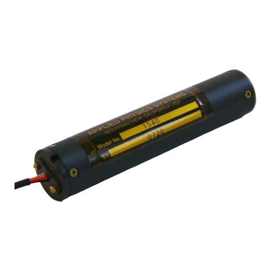
Figure 1. Model 1540 Cylindrical Magnetometer Updated the Model 1540S mechanical drawing. Figure 2. Model 1540S Rectangular Magnetometer Mechanical Drawing Updated the Model 1540 and 1540S electrical April 2017 interface. Table 3. Model 1540S Electrical Interface, Figure 2. Model 1540S Rectangular... -
Page 4: Table Of Contents
5.5.1 - CHANGING THE ASCII DATA OUTPUT MODE ....................23 5.5.2 - CHANGING THE BAUD RATE ............................ 23 5.5.3 - CONFIGURING THE MODEL 1540 SENSOR FOR AUTOSEND ..............24 5.5.4 - AVERAGING AND FILTERING MODEL 1540 OUTPUT DATA ............... 25 5.6 - USING THE ASCII COMMUNICATION MODE ....................... - Page 5 Figure 2. Model 1540S Rectangular Magnetometer Mechanical Drawing ....... 10 Figure 3. Model 1540 with Leads ........................11 Figure 4. Averaging Example ......................... 26 Figure 5. Model 1540 Noise Level Data ....................... 31 Figure 6. Sensor Interfacce Main Display ....................33 Figure 7. Sensor Configure Window ......................34 Figure 8.
-
Page 6: Introduction
• external computer The Model 1540 is calibrated by placing it in a precision 3-axis Helmholtz coil, which enables the application of accurately known magnetic fields to the system. Then the Helmholtz coil is fitted with a holding fixture with alignment holes and reference V grooves that match the 1540 alignment pins and cylindrical body. -
Page 7: System Specifications
The default baud rate is 9600 with one stop bit, no parity and 8 data bits. An autosend data mode is included in the 1540 software. When this mode is active, data is repeatedly sent out the serial port automatically after power is applied to the system. - Page 8 DOC PN: 260-0183 DOC DESC: Model 1540 User Manual JULY 2022. REVISION: 03 Alignment of sensor Better than ±0.2° package with sensor reference surfaces Noise Level ±0.5 nT (±5 μGauss) peak-to-peak Frequency Response DC to 400 Hz (-3 db) Analog Bandwidth...
-
Page 9: Mechanical Features
JULY 2022. REVISION: 03 3 - MECHANICAL FEATURES The cylindrical 1540 has an alignment slot on the top surface. This slot aligns with the Z+ axis direction. The 1540 coordinate directions are shown in Figure magnetic field direction aligned with the axis direction arrows will produce a positive output voltage. -
Page 10: Figure 2. Model 1540S Rectangular Magnetometer Mechanical Drawing
DrawingFigure 2. Model 1540S Rectangular Magnetometer Mechanical Drawing Figure 2. Model 1540S Rectangular Magnetometer Mechanical Drawing Both the Model 1540 and the Model 1540S have a 9-pin MDM connector for powering and computer interface. APPLIED PHYSICS SYSTEMS, INC. | APPLIEDPHYSICS.COM... -
Page 11: Electrical Interface
JULY 2022. REVISION: 03 4 - ELECTRICAL INTERFACE The Model 1540 powers from a single input voltage that can range from +4.95 V to +12 V. Six flying leads (#28 gauge Teflon insulated) are used to connect to the 1540, as shown in Figure 3. -
Page 12: Table 2. Model 1540 Electrical Interface
DOC PN: 260-0183 DOC DESC: Model 1540 User Manual JULY 2022. REVISION: 03 Table 2. Model 1540 Electrical Interface Flying Lead Wire Color Function MDM Connector Pin Orange RS-232 serial IN 1 (black) (or Y RS-422) Yellow RS-232 serial OUT... -
Page 13: Table 3. Model 1540S Electrical Interface
DOC PN: 260-0183 DOC DESC: Model 1540 User Manual JULY 2022. REVISION: 03 Table 3. Model 1540S Electrical Interface Flying Lead Wire Color Function MDM Connector Pin RS-232 serial IN Black 1 (black) (or Y RS-422) RS-232 serial OUT Brown... -
Page 14: Setting Up The Electrical Connections
PC COM port connector on the computer. 4. Apply power to the + voltage and ground wires. 5. Adjust the input voltage to a value between +5 V and+12 V. The 1540 uses low dropout linear regulators to produce internal working voltages of ±4.5 V, so the lower the input voltage the lower the power consumed by the 1540. - Page 15 COM port and select the baud rate 9600 with one stop bit and no parity. 8. To determine if communication with the 1540 has been established, look at 1540 sign on message that is transmitted at 9600 baud when power is turned on.
-
Page 16: Computer Interface
Observe the PC display when the 1540 is powered up to see if communications with the 1540 has been established. The 1540 will transmit a sign on message at power up, which should appear in readable form on the PC display. If the sign on message is unreadable, you may have selected an incorrect baud rate on the computer. -
Page 17: Table 4. Model 1540 Commands
DOC PN: 260-0183 DOC DESC: Model 1540 User Manual JULY 2022. REVISION: 03 step process using sensor commands 0l and 0wc. The two step process is used to ensure these constants are not accidentally changed. Enter the 0l command (zero and the letter L) before using the write •... - Page 18 DOC PN: 260-0183 DOC DESC: Model 1540 User Manual JULY 2022. REVISION: 03 Test Serial Port 0TestSerialPort 0777 Ver: Return Software Version 3.85BD7716F 0TestVersion Enable Writing Enabled! 0WC<constant Write to a Float Constant number>F<value> Done 0WriteConstant<>Float<> Table 13. Model 1540 Float Constants 0WC<constant...
-
Page 19: 1540 Byte Constants
JULY 2022. REVISION: 03 5.2 – MODEL 1540 BYTE CONSTANTS System constants include byte constants and float constants. Byte constants are used to configure the 1540 system and are used when operating the 1540. See Table 5. Commonly Used Byte Constants Float constants are used for system calibration, diagnostics, and troubleshooting and generally not used when operating the 1540. -
Page 20: Model 1540 Float Constants
ASCII - The ASCII protocol is based sending ASCII characters (commands) to the 1540 to obtain data. Data transmitted in response to a command is sent out as an ASCII data stream complete with returns and line feeds so that it can be easily displayed on a PC display terminal (provided a TTL to RS-232 conversion box is used). - Page 21 Binary - The binary 1540 protocol is used for high speed computer-to- computer interchange. In this case, one byte is sent to request data. The 1540 then responds with a multibyte data packet containing the desired data plus header, checksum, and footer.
-
Page 22: Configuring The Model 1540 System
DOC PN: 260-0183 DOC DESC: Model 1540 User Manual JULY 2022. REVISION: 03 5.5 - CONFIGURING THE MODEL 1540 SYSTEM This section provides instructions about using the most common configuration options for the 1540 system. Changing data output modes (see Section •... - Page 23 DOC PN: 260-0183 DOC DESC: Model 1540 User Manual JULY 2022. REVISION: 03 5.5.1 - CHANGING THE ASCII DATA OUTPUT MODE) • Changing baud rates (see Section 5.5.2 - CHANGING THE BAUD RATE) • Configuring for autosend (see Section 5.5.3 - CONFIGURING THE MODEL •...
-
Page 24: Changing The Ascii Data Output Mode
JULY 2022. REVISION: 03 5.5.1 - CHANGING THE ASCII DATA OUTPUT MODE To change the 1540 to A/D count mode, byte constant 02 must be changed from 02 (sensor mode) to 00 (count mode). The response will look something like this. -
Page 25: Configuring The Model 1540 Sensor For Autosend
5.5.3 - CONFIGURING THE MODEL 1540 SENSOR FOR AUTOSEND The Model 1540 has an autosend mode that enables data to automatically be sent repeatedly on power up. Byte constant 01 = 5A for autosend mode to be active. The format of the data sent in autosend mode is determined by the value of byte constant 08. -
Page 26: Averaging And Filtering Model 1540 Output Data
DOC PN: 260-0183 DOC DESC: Model 1540 User Manual JULY 2022. REVISION: 03 Table 8. Autosend Modes Byte Constant Autosend Mode 08 Value Send ASCII data continuously on power up. Use for repetitive text transmissions. Send binary data continuously on power up. -
Page 27: Using The Ascii Communication Mode
When a new data point is acquired, a new average is computed by dropping the oldest data point from the average and adding the new data point. The response of the 1540 to a 0.5 Gauss step input for various averaging values is shown in the Figure 4. -
Page 28: Ascii Autosend Mode
DOC DESC: Model 1540 User Manual JULY 2022. REVISION: 03 TEMP: +28.148 When byte constant 02 = 02, the 1540 is in sensor output mode and the above numbers represent the magnetometer X, Y and Z sensor outputs in Gauss. 5.6.1 - ASCII AUTOSEND MODE... -
Page 29: Command <128>: Send Sensor (Vector) Data In Standard Binary Format
DOC PN: 260-0183 DOC DESC: Model 1540 User Manual JULY 2022. REVISION: 03 5.7.1 - COMMAND <128>: SEND SENSOR (VECTOR) DATA IN STANDARD BINARY FORMAT This section describes the contents of a binary packet. Note that when a Command <128> Send Vector Data command is issued, the response always begins with 0x80. -
Page 30: Command <129>: Send All Data As Vectors In An Ieee Float Format
DOC PN: 260-0183 DOC DESC: Model 1540 User Manual JULY 2022. REVISION: 03 <DATA CHECK The lower 8 bits of the sum of all the bytes in 1 Byte SUM> the data area. <EOT> The end of the transfer, shown as 0x7FFF... -
Page 31: Autosend Binary Communication Mode
(optional) 6 - OPERATING THE MODEL 1540 After the Model 1540 is operational and communicating with a computer, its proper operation can be qualitatively verified by using it to measure the Earth's magnetic field. Around the globe, the magnitude of the Earth's magnetic field varies from about 0.4 Gauss to 0.6 Gauss. -
Page 32: Sensor Interface Software
DOC DESC: Model 1540 User Manual JULY 2022. REVISION: 03 The noise level of the 1540 can be observed by placing the sensor in a magnetic shield, which typically consists of a 2 layer mu metal shield. An example of data taken using ASCII autosend mode with the 1540 positioned in a mu metal shield is shown in Figure 5. - Page 33 DOC PN: 260-0183 DOC DESC: Model 1540 User Manual JULY 2022. REVISION: 03 programmed for ASCII or binary transfer modes and for corrected or non- corrected data. Sensor Interface software also creates log files of sensor data and displays a scrolling graph of the digital data and graphical indicators of the angular data with the minimum and maximum values maintained for the magnetometer.
-
Page 34: Figure 6. Sensor Interfacce Main Display
DOC PN: 260-0183 DOC DESC: Model 1540 User Manual JULY 2022. REVISION: 03 Figure 6. Sensor Interfacce Main Display The upper left corner of the main window contains the following command buttons. The Monitor button brings up the monitor window. -
Page 35: Figure 7. Sensor Configure Window
DOC PN: 260-0183 DOC DESC: Model 1540 User Manual JULY 2022. REVISION: 03 In the View menu, each check mark before Magnetometer Min/Max or AC/DC Magnetic enables or disables the feature from appearing on the screen. In Figure the Magnetometer Min/Max is enabled. - Page 36 To save data output from the 1540, enter a log file name in the Log File panel. The file will capture all data sent to the software from the sensor. The type of data logged is set in the menu in the Monitor window and can be either ASCII for Logging or Hex for Logging.
-
Page 37: Figure 8. Monitor Sensor Window
DOC PN: 260-0183 DOC DESC: Model 1540 User Manual JULY 2022. REVISION: 03 Figure 8. Monitor Sensor Window The Monitor Sensor window has six display modes. ASCII. In ASCII mode, the Monitor Sensor window acts like a simple ASCII •... -
Page 38: Figure 10. Monitor Sensor Window - Hex Mode
DOC PN: 260-0183 DOC DESC: Model 1540 User Manual JULY 2022. REVISION: 03 Hex. In Hex mode, each ASCII character received is converted to the • hexadecimal value that it represents, followed by a space. For example, the ASCII character 'A' would be printed as '41', which is its hexadecimal value. -
Page 39: A - Byte Constants And Float Constants
Although there are many byte constants, only a subset of them is commonly used. Table 1 displays a complete list of Model 1540 byte constants for your reference. For a list of the commonly used byte constants, see Table 5. Commonly Used Byte Constants Table 12. - Page 40 DOC PN: 260-0183 DOC DESC: Model 1540 User Manual JULY 2022. REVISION: 03 Auto Start Mode. On power up start accepting commands and then If 01=00 and 08=10 Send All Data in text mode once. If 01=00 and 08=11 Send All Data in binary mode once.
- Page 41 DOC PN: 260-0183 DOC DESC: Model 1540 User Manual JULY 2022. REVISION: 03 19200 ==> 5 3840 ==> 6 To change the baud rate from 9600 (default), lock the baud rate, change the baud rate, and then power cycle the unit.
- Page 42 DOC PN: 260-0183 DOC DESC: Model 1540 User Manual JULY 2022. REVISION: 03 Product ID String char #4 Product ID String char #5 Product ID String char #6 Product ID String char #7 Product ID String char #8 Product ID String char #9...
-
Page 43: Model 1540 Float Constants
A.2 – MODEL 1540 FLOAT CONSTANTS Float constants are commonly used by Applied Physics Systems for diagnostics and troubleshooting. Although float constants are not commonly used when operating the 1540 system, a complete list of float constants are included in Table 13 for your reference.
Need help?
Do you have a question about the 1540 and is the answer not in the manual?
Questions and answers