Advertisement
Quick Links
Advertisement

Related Manuals for DR VERSA TRAILER PRO XL2000


Summary of Contents for DR VERSA TRAILER PRO XL2000
- Page 1 ® VERSA TRAILER™ SAFETY & OPERATING INSTRUCTIONS Model: PRO XL2000 DR Power Equipment Serial No. Toll-free phone: 1-800-DR-OWNER (376-9637) Order No. Website: www.DRpower.com Read and understand this manual and all instructions before assembling and operating the DR VERSA TRAILER.
-
Page 2: Table Of Contents
Additional Information and Potential Changes DR Power Equipment reserves the right to discontinue, change, and improve its products at any time without notice or obligation to the purchaser. The descriptions and specifications contained in this manual were in effect at printing. Equipment described within this manual may be optional. -
Page 3: Chapter 1: General Safety Rules
Labels Your DR VERSA TRAILER carries prominent labels as reminders for its proper and safe use. Shown below are copies of all the Safety and Information Labels that appear on the unit. Take a moment to study them and make a note of their location on your DR VERSA TRAILER as you set up and before use of your Trailer. - Page 4 Never overload the Trailer. Personal injury or damage to the Trailer may result. Damage caused to the Trailer can void the Warranty. While using the DR VERSA TRAILER, don't hurry or take things for granted. When in doubt, stop the Tow Vehicle and take the time to look things over.
- Page 5 Make sure the DR VERSA TRAILER is not overloaded and that the load is properly distributed front to back and side to side and properly secured to prevent shifting of the load during transportation. Shifting, or uneven loads may result in the loss of control of the Trailer or Tow Vehicle.
-
Page 6: Chapter 2: Assembling The Dr Versa Trailer
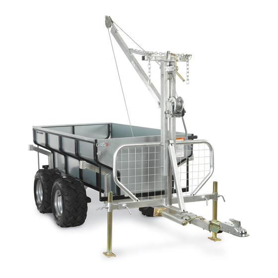
Chapter 2: Assembling the DR VERSA TRAILER It may be helpful to familiarize yourself with the features of your DR VERSA TRAILER as shown in Figure 1 before beginning these procedures. If you have any questions at all, please feel free to contact us at www.DRpower.com. - Page 7 31.25 Cubic Feet Unpacking the DR VERSA TRAILER Due to the weight of the components of the DR VERSA TRAILER, we strongly recommend that you have the help of at least one other person in unpacking and assembling your new Trailer.
- Page 8 The Parts shown here are included in the Hardware Kit Bag (2) Safety Snap Pin (302751) (4) M8 Bolt x 30mm (302451) Wheel Stud (299601) (4) M8 Lock Nut (302461) Wheel Dust Cap (17) Lug Nut (299781) (299611) (2) Axle Pivot Pin (302441) (2) M10 Bolt x 90mm (302511) (2) Tow Hitch Spacer (302841) (2) M10 Lock Nut (302491)
- Page 9 (2) Axle and Hub Assembly (299581) Main Frame (299571) (4) Wheel and Tire Assembly (299641) Front Bed Support Rear Bed Support (4) Log Cradle (299661) Pivoting Tow Hitch (299651) (4) Log Cradle Extension (299691) (302701) (299671) Crane Pivot Lock (2) Stabilizer Bracket (277151) (299731) Operator Guard (299711) Vertical Crane Support...
- Page 10 Installing the Wheels and Tow Bar to the Main Frame Tools Needed: 13-1/2" Two Adjustable Wrenches capable of tightening a 30mm or 1-1/2" Bolt Head. 13mm Wrench required (12, 18, & 30mm Wrenches optional if two Adjustable Wrenches are available) ...
- Page 11 NOTE: The Wheels are marked L (Left) and R (Right), as they are directional Tires. Front Since the Main Frame is upside down, the Left Wheels should be installed on the Right Side and the Right Wheels on the Left Side (Figure 8). Make sure the Valve Stem(s) face outwards.
- Page 12 Install a M20 x 110mm Bolt and Washer (Figure 13) in the Mounting Hole, M20 Lock and install a M20 Lock Nut. Tighten with Adjustable Wrenches or a 30mm Socket and an Adjustable Wrench. 10. Back the Jam Nuts on the four Retaining Bolts (Figure 14) all the way to the head of the Bolts.
- Page 13 2. Install and tighten two M12 x 50mm Bolts and Jam Nuts with an 18mm Socket for the Bolts and an 18mm Wrench for the Nuts (Figure 17). 3. Slide the Operator Guard onto the Tow Bar with the Mounting Bosses facing to the Left, 26"...
- Page 14 Brackets 4. When you have determined the best Flange setting, reposition the Jack 10- Locknut and 1/2" from the end of the Tow Bar and secure with the Brackets (tabs against Lock Washer Tow Bar), Bolts (head on Flange side), Lock Washers (Locknut side) and Locknuts (Figure 18C).
- Page 15 Installing the Pivoting Tow Hitch w/ Coupler Tools Needed: 16mm Socket Pivoting Tow Hitch 17mm Wrench Swivel Install the Pivoting Tow Hitch (Figure 19) into the Tow Beam with the Swivel facing upward. Install two M10 x 90mm Bolts and Spacers, with the smaller diameter Shoulder(s) down, (Figure 20) through the Tow Bar and Pivoting Tow Hitch.
- Page 16 Lock Nut, Flat Attaching the Crane Washer and Tabbed Washer Tools Needed: Boom Pivot 22mm and 17mm Wrench M10 Lock Nut 21mm, 16mm and 30mm Sockets Large Adjustable Wrench 1. Remove the Lock Nut, Flat Washer, and Tabbed Washer from M10 Bolt the top of the Crane (Figure 24) along with the Pivot Lock Handle by removing the M10 x 1.75mm Bolt and M10 Lock...
- Page 17 5" Long Socket Extension Adjustable Wrench NOTE: Before installing the Winch and Boom to your DR VERSA TRAILER, follow the Boom Swivel instructions shipped with your Winch to properly install the Handle and Cable. Bracket You may want to install the Cable after the Winch has been installed to your Trailer.
- Page 18 Reinstall the Boom Swivel Bracket and hardware, and then remove the Hitch Clip Pin and Pin from the Bracket (Figure 34). Install the Boom to the Boom Swivel Bracket with the Chain Attachment Bracket on the Boom pointing up (Chains not shown for clarity), using the Hitch Clip Pin and Pin that was removed in step 5 (Figure 35).
- Page 19 Installing the Rear Bed Support and Attaching to a Tow Vehicle Tools Needed: Main Frame 18mm and 30mm Socket 18mm Wrench Boss Adjustable Wrench 1/2" Drive Torque Wrench Rear Bed Support 5" Long 1/2" Drive Socket Extension ...
- Page 20 11. Loosen the Locking Handles for the Stabilizer Legs and raise them to the highest position for towing. Re-tighten the Locking Handles and rotate the Trailer Jack to the Tow position (Figure 42). 12. Torque the Lug Nuts on each Wheel to 70-80 ft-lbs using a Torque Wrench, a 5"...
- Page 21 6. Attach the Hook from the Winch to the U-Bolt in the Bed (Figure 48). 7. Check and adjust the Tire Pressures to 25-28 PSI prior to use. 8. CONGRATULATIONS! Your DR VERSA TRAILER is now ready to use! See the next Chapter for operating suggestions and tips.
-
Page 22: Chapter 3: Operating The Dr Versa Trailer
Chapter 3: Operating the DR VERSA TRAILER This chapter covers the basic operation procedures for your new DR VERSA TRAILER. It may be helpful to better familiarize yourself with the features of your Trailer by reviewing Figure 1 in Chapter 2 before beginning the following steps. - Page 23 Before loading the Trailer with the Winch, extend the Outriggers no more than 15" outwards from the end of the Operator Guard (Figure 49) and lower the Adjustable Stabilizer Legs to the ground and tighten the Locking Handles. Once you have finished loading the Trailer, raise the Adjustable Stabilizer Legs and retract the Outriggers for travel.
- Page 24 Using the Winch and Boom to Load Logs onto the Trailer Always stand on the Crank Handle side of the Winch (Figure 52), never directly in line with the Winch Cable, and always behind the Operator Guard! If the Winch Cable is kinked, frayed, or otherwise damaged, do not use it. Replace the Cable immediately. ...
-
Page 25: Chapter 4: Maintaining The Dr Versa Trailer
Chapter 4: Maintaining the DR VERSA TRAILER Regular maintenance is the way to ensure the best performance and long life of your Trailer. Please refer to this manual for maintenance procedures. Regular Maintenance Checklist Before inspecting, or performing any Maintenance make sure the Tow Vehicle is properly Parked on Level Ground and the Wheels of the Trailer are chocked. - Page 26 Greasing the Tow Ball, Tow Hitch, and Grease Fittings Your DR VERSA TRAILER'S Wheel Bearings were greased at the Factory. Prior Grease Fitting to using your Trailer for the first time, you need to lubricate the Axle Pivot Pins, Swivel of the Tow Hitch, the Tow Hitch Coupler, and the 2" Ball you will be using.
- Page 27 Adjusting the Tow Hitch A loose connection between the Trailer and Tow Vehicle may cause the Hitch to disconnect or rattle during use. Always check the Hitch for proper tension prior to use. Tool Needed: 19mm Socket or Wrench Attach the empty Trailer to the Tow Vehicle and latch the Locking Lever. Check for horizontal and vertical play between the Tow Hitch and the 2"...
- Page 28 Wheel Bearing Replacement and/or Greasing Tools and Supplies Needed: Safety Glasses and Gloves Jack and Two Jack Stands Rags and Wheel Bearing Grease Flathead Screwdriver Needle Nose Pliers Wire Cutters (Dikes) Soft Faced Hammer ...
-
Page 29: Chapter 5: Troubleshooting
Most problems are easy to fix. Consult the Troubleshooting Table below for common problems and their solutions. If you continue to experience problems, contact us at www.DRpower.com or call toll-free 1-800-DR-OWNER (376-9637) for support. Shut down the Tow Vehicle Engine and apply the Parking Brake before performing any maintenance procedure or inspection on the DR VERSA TRAILER. -
Page 30: Chapter 6: Parts Lists And Schematic Diagrams
Chapter 6: Parts Lists and Schematic Diagrams Parts List – DR VERSA TRAILER Dump Bed Assembly Note: Part numbers listed are available through DR Power Equipment. Ref# Part# Description 299841 Rear Tailgate, w/Label 299851 Front Tailgate 302401 Hex Nut, Heavy, M12-1.75, Class 8, ZP 302651 U-Bolt, 50mm x M12-1.75... - Page 31 Schematic – DR VERSA TRAILER Dump Bed Assembly CONTACT US AT www.DRpower.com...
- Page 32 Parts List and Schematic – DR VERSA TRAILER Crane and Boom Assembly Note: Part numbers listed are available through DR Power Equipment. Ref# Part# Description Ref# Part# Description 299651 Front Bed Support 302601 Bolt, HHCS, M8-1.25 x 100, Class 8,...
- Page 33 Schematic – DR VERSA TRAILER Crane and Boom Assembly CONTACT US AT www.DRpower.com...
- Page 34 Parts List – DR VERSA TRAILER Main Frame and Axle Assembly Note: Part numbers listed are available through DR Power Equipment. Ref# Part# Description 302711 Tow Bar w/Labels 299581 Axle and Hub Assembly 299641 Wheel and Tire Assembly, Off Road...
- Page 35 Schematic – DR VERSA TRAILER Main Frame and Axle Assembly CONTACT US AT www.DRpower.com...
- Page 36 Parts List – DR VERSA TRAILER Operator Guard, Trailer Jack, Rear Bed Support, and Pivoting Tow Hitch Note: Part numbers listed are available through DR Power Equipment. Ref# Part# Description 277241 Ball Coupler, 2" 299711 Operator Guard 277151 Stabilizer Bracket...
- Page 37 Schematic – DR VERSA TRAILER Operator Guard, Trailer Jack, Rear Bed Support, and Pivoting Tow Hitch CONTACT US AT www.DRpower.com...
- Page 38 DR Power Equipment however, limits the implied warranties of merchantability and fitness in duration to a period of two (2) years in consumer use, ninety (90) days for any other use.
- Page 39 CONTACT US AT www.DRpower.com...
- Page 40 If possible, store the DR VERSA TRAILER in a dry, protected place. If it is necessary to store the Trailer outside, cover the Trailer with a suitable protective cover that does not retain moisture. Do not use plastic as this material cannot breathe; it also allows condensation to form, which may cause your Trailer to rust.
Need help?
Do you have a question about the VERSA TRAILER PRO XL2000 and is the answer not in the manual?
Questions and answers