Table of Contents
Advertisement
Quick Links
Advertisement
Table of Contents

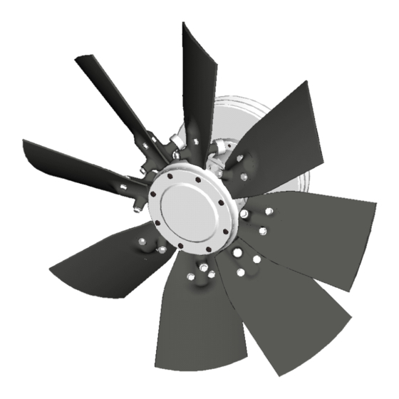
Summary of Contents for Flexxaire FX 2000 Series
- Page 1 FLEXXAIRE ® ENGINE TEMPERATURE CONTROL SYSTEMS FX 2000 FAN SERIES (HYDRAULIC PITCH CONTROL) IF BOX IS CHECKED, REFER WITHIN FRONT COVER PAGE OF THIS MANUAL FOR SPECIAL INSTRUCTIONS. Publication No. 01523 Revision 7 Printed in Canada June 14, 2007 Hydraulic Manual 01523r7.wpd...
- Page 2 Page 0-2 01523r7.wpd Hydraulic Manual June 14, 2007 Printed in Canada...
-
Page 3: Table Of Contents
Table Of Contents SECTION 1. GENERAL INFORMATION ........... . 1-1 1.1. - Page 4 Page 0-4 01523r7.wpd Hydraulic Manual June 14, 2007 Printed in Canada...
-
Page 5: Section 1. General Information
SECTION 1. GENERAL INFORMATION SECTION 1. GENERAL INFORMATION ........... . 1-1 1.1. - Page 6 Page 1-2 01523r7.wpd Section 1 - General Information & Overview June 14, 2007 Printed in Canada...
-
Page 7: Introduction
1.1. INTRODUCTION This manual (P/N 01523) is produced to assist in the The person(s) servicing the product may be unfamiliar ® installation and operation of the Flexxaire FX Series with many of the systems or components on the fan systems. -
Page 8: Fan Overview
A. If possible, make all repairs to the fan assembly The fan blades of the Flexxaire fan vary pitch, not fan on an engine stand or any other suitable stand. Do speed, to control air flow and direction. -
Page 9: Section 2. Hydraulic Fan Group
SECTION 2. HYDRAULIC FAN GROUP SECTION 2. HYDRAULIC FAN GROUP ........... . 2-1 2.1. - Page 10 Page 2-2 01523r7.wpd Section 2 - Hydraulic Fan Group June 14, 2007 Printed in Canada...
-
Page 11: Introduction
External Identifiable Components 2.1. INTRODUCTION The Hydraulic Fan Assembly can be identified by ® This manual explains Flexxaire ’ s FX series of fan several external major components in Figure 1. Use systems. The FX fan blade pitch is controlled this diagram for terminology and component hydraulically through two hydraulic ports. -
Page 12: Installation
B. Attach hoisting device to remove hub assembly from shipping crate. The following describes the removal of an existing fan ® and the installation of a Flexxaire FX Fan assembly NOTE: When lifting hub assembly, use a proper onto your application. -
Page 13: Hydraulic Control Installation Guide
Note: If any of the supplied flanged lock nuts are lost or need to be replaced, they may be ® The Flexxaire FX Fan assembly requires a hydraulic substituted with grade 8 flanged nuts. source and valving to operate. Loctite® 242 or equivalent must be applied to the bolt if lock nuts are not used. -
Page 14: Hydraulic Specifications
The Flexxaire FX fan can be controlled with ® Interval Of Pitch Change: The Flexxaire fan should a 2 or 3 position solenoid valve, or a full variable pitch be operated at a pitch change rate of not less then ®... -
Page 15: Hydraulic Valve Installation
NOTE: An orifice is used to control the speed at ® which the pitch changes and is installed on The following will be specific to Flexxaire control kits the return line of the hydraulic system being but would apply to similar setups. -
Page 16: Hydraulic Control Set-Up
2.2.2.6. Hydraulic Control Set-Up B. Start engine to develop hydraulic pressure. ® The following control set-up is specific to Flexxaire C. Toggle Air Flow switch (Item 3) several times to control groups but would apply to similar set-ups. purge air from newly installed hydraulic lines. -
Page 17: Fx Fan Operation
If the cycle is too long, drill out the orifice. If the cycle position. Do this until the correct switch is is too short a smaller orifice is required. Contact your ® local hydraulics supplier or Flexxaire for orifice. obtained. E. Toggle the Air Flow Switch to change air flow to 2.2.2.7. -
Page 18: Service And Maintenance
These everyday best practices are recommended An optional oil level check is recommended for to keep your Flexxaire fan system working for you. every 1000 operational hours or if there is reason to believe the fan is losing oil. The fan contains 2.3.1.1 Fan Blades... -
Page 19: Checking Oil Level And Adding/Draining Oil
C. Insert an appropriate dipstick into the hub through again. Repeat until one hole is at the 6:00 position the drain plug at 12:00. (Flexxaire does not supply and the other at the 4:00 position and all oil has a dipstick.) drained from hub. -
Page 20: Maintenance Check List
2.3.3. Maintenance Check List This check list is to provide some basic information to be used at time of machine delivery. If you answer “ NO” to any of the questions, then the situation must be corrected before machine goes into service. CHECK If your fan is a “Pull”...


Need help?
Do you have a question about the FX 2000 Series and is the answer not in the manual?
Questions and answers