Advertisement
Quick Links
Advertisement

Summary of Contents for Flexxaire KUBOTA M5-111
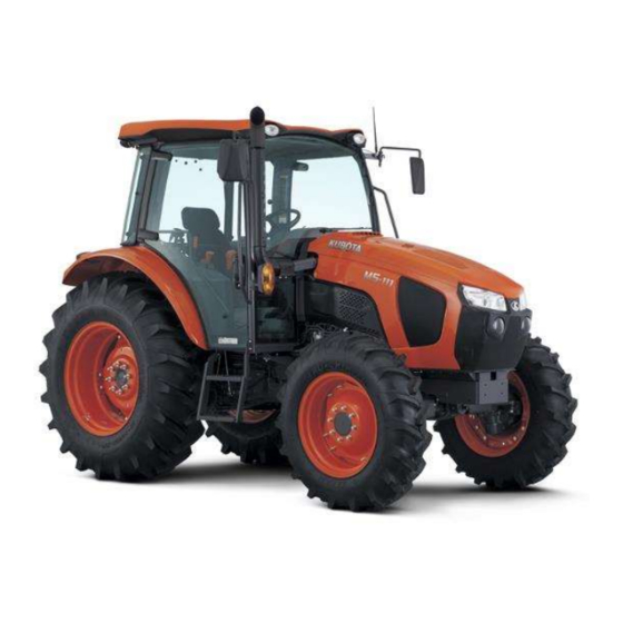
- Page 1 KUBOTA M5-111 Reversible Fan Installa on Guide (02131r1)
- Page 2 Airline ¼” (150” x1) Toggle reversing switch (x1) Grommet ¼” – ½” (x1) FLEXXAIRE COMPRESSOR AIRFILTER RELOCATION KIT P/N 90485 Airline ¼” (120” x1) Airfilter (x1) NOTE: all orienta on is referenced as-if si ng in operator seat ...
- Page 3 INSTRUCTIONS FOR REMOVAL OF OEM FAN 1. Open hood and remove engine access panels from both sides of the engine. ENGINE ACCESS PANELS ENGINE ACCESS PANELS 2. Remove items required to gain access to the fan. Items can include fan shroud, brackets, hoses, etc. If required, remove or adjust hoses/tubing from sides of engine to expose the OEM fan.
- Page 4 Follow installa on instruc ons from Flexxaire as no addi onal modifica ons are required for this applica on In addi on to this manual (XXXXX) reference to the following documents is required for supplemental instruc ons and safety considera ons ...
- Page 5 4. Remove the shipping plug from the rear of the fan prior to bol ng onto adapter. (see pictures to the right) 5. Locate (x3) bolts M8 x 1.25 x 30MM GR 10.9 (Flexxaire p/n 11875). 6. Place fan into engine compartment and finger-thread the 3 bolts to secure fan to moun ng adapter.
- Page 6 INSTRUCTIONS FOR AIRLINE INSTALLATION TO FAN 1. Drill a 15/32” hole on bo om right corner of fan shroud for the supply airline and install the rubber grommet. 2. Insert airline through the grommet and leave approx. 24” s cking into the fan shroud. BOTTOM RIGHT CORNER OF FAN SHROUD...
- Page 7 INSTRUCTIONS FOR COMPRESSOR INSTALLATION 1. Locate the cab access panel/port under the cab at front right. CAB ACCESS PANEL/PORT CAB ACCESS PANEL/PORT COMPRESSOR / VALVE ASSEMBLY 2. Locate compressor / valve assembly and thread the ¼” fi ng into port 2 of the valve. 3.
- Page 8 INSTRUCTIONS FOR CONNECTIONS AND ROUTING OF AIRLINE 1. Route ¼” airline exi ng from the right bo om of fan shroud along the frame and exis ng lines to the push-in fi ng previously installed on port 2 of the compressor valve. NOTE: Secure airline from fan with zip es as required.
-
Page 9: Power Cable
INSTRUCTIONS FOR ELECTRICAL CONNECTIONS BETWEEN TIMER, COMPRESSOR AND POWER CABLE 1. From inside the cab, feed the wire lead with receptacle from the mer through the floor using the cab access panel/port inside the right console. 2. Connect the receptacle from the mer to the plug on the compressor. WIRE LEAD FROM TIMER TIMER ENCLOSURE BOX TIMER ENCLOSURE... - Page 10 INSTRUCTIONS FOR CONNECTING THE POWER CABLE 1. Locate manual override toggle switch. 2. Locate blank accessory plate on console to the right of operator’s seat and remove it from console. 3. Place manual override switch on blank accessory plate to layout the hole loca on and drill a 1/2” hole. 4.
- Page 11 INSTRUCTIONS FOR ROUTING AND CONNECTING THE POWER CABLE 10. Connect the black (ground) wire from the power cable to the grounding stud next to fuse panel inside the console. 11. Locate a suitable source for keyed power at the fuse box. ex. radio, 12V plug, etc. 12.
- Page 12 +1-780-483-3267 TOLL FREE IN NORTH AMERICA 1-866-489-3267 SUPPORT support@flexxaire.com +1-780-483-3267 TOLL FREE IN NORTH AMERICA 1-866-489-3267 FLEXXAIRE INC. THANK YOU 10430—180 STREET, EDMONTON, AB, CANADA +1 780 483 3267 www.flexxaire.com...


Need help?
Do you have a question about the KUBOTA M5-111 and is the answer not in the manual?
Questions and answers