
Subscribe to Our Youtube Channel
Related Manuals for Teledyne Lecroy HDO8000


Summary of Contents for Teledyne Lecroy HDO8000
- Page 1 Operator's Manual Motor Drive Analyzer/ HDO8000 8-Channel High Definition Oscilloscope...
- Page 2 However, clients are encouraged to duplicate and distribute Teledyne LeCroy documentation for their own internal educational purposes. HDO and Teledyne LeCroy are trademarks of Teledyne LeCroy, Inc. Other product or brand names are trademarks or requested trademarks of their respective holders. Information in this publication supersedes all earlier versions.
-
Page 3: Table Of Contents
Operator's Manual Contents Safety Instructions Operating Environment Cooling Power Start Up Carrying and Placing Positioning the Feet Powering On/Off Software Activation X-Stream Application Window Screen Saver Front Input/Output Panel Analog Inputs Probes Digital Inputs Back Input/Output Panel Connecting to Other Devices/Systems User Interface Front Panel Touch Screen... - Page 4 Motor Drive Analyzer/HDO8000 High-Definition Oscilloscope Setting Up Triggers Software Assisted Trigger TriggerScan Display Display Mode vs. Grid Mode Multi-Grid Displays Display Settings Persistence Cursors Cursor Types Cursors on Math Functions Cursor Settings Measure Quick Measurements Setting Up Custom Measurements Math on Parameters...
- Page 5 Operator's Manual Date/Time Settings Options Disk Utilities Preferences Settings Acquisition Settings E-Mail Color Settings Miscellaneous Settings Save/Recall Save Setups Recall Setups Save Waveforms Recall Waveforms Save Table Data LabNotebook Create Notebook Entry LabNotebook Drawing Toolbar Manage Notebook Entries Manage Notebooks Print to Notebook Entry Flashback Recall Customize Reports...
- Page 6 Motor Drive Analyzer/HDO8000 High-Definition Oscilloscope Welcome Thank you for purchasing a Teledyne LeCroy Motor Drive Analyzer (MDA) or HDO8000 oscilloscope. We're certain you'll be pleased with the detailed features unique to our instruments. The manual is arranged in the following manner: Safety contains important precautions and information relating to power and cooling.
-
Page 7: Safety Instructions
Operator's Manual Safety Instructions Observe these instructions to keep the instrument operating in a correct and safe condition. You are required to follow generally accepted safety procedures in addition to the precautions specified in this section. The overall safety of any system incorporating this instrument is the responsibility of the assembler of the system. -
Page 8: Operating Environment
Motor Drive Analyzer/HDO8000 High-Definition Oscilloscope Do not operate with suspected failures. Do not use the product if any part is damaged. Obviously incorrect measurement behaviors (such as failure to calibrate) might indicate impairment due to hazardous live electrical quantities. Cease operation immediately and sequester the instrument from inadvertent use. -
Page 9: Start Up
Operator's Manual Start Up Carrying and Placing The instrument’s case contains a built-in carrying handle. Lift the handle away from the body, grasp firmly and lift the instrument. Always unplug the instrument from the power source before moving it. Place the instrument where it will have a minimum 15 cm (6 inch) clearance from the nearest object. Be sure there are no papers or other debris underneath or blocking the cooling vents. -
Page 10: Software Activation
The operating software (firmware and standard applications) is active upon delivery. At power-up, the instrument loads the software automatically. Firmware Free firmware updates are available periodically from the Teledyne LeCroy website at: teledynelecroy.com/support/softwaredownload Registered users can receive an email notification when a new update is released. Follow the instructions on the website to download and install the software. -
Page 11: Front Input/Output Panel
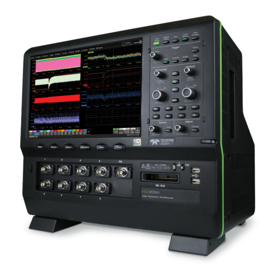
Front Input/Output Panel HDO8000 Motor Drive Analyzer A. Shortcut buttons to quickly access functions. Note the options differ between HDO8000 and MDA models. B. Power button. C. Channel inputs 1-8 for analog signals, and EXT to input an external trigger. -
Page 12: Analog Inputs
System (probe plus instrument) gain settings are automatically calculated and displayed based on the probe attenuation. Probes The MDA/HDO8000 is compatible with the included passive probes and all Teledyne LeCroy ProBus active probes that are rated for the instrument’s bandwidth. Probe specifications and documentation are available at teledynelecroy.com/probes. -
Page 13: Digital Inputs
Operator's Manual Digital Inputs Delivered with the HDO8K-MSO option, the digital leadset enables input of up-to-16 lines of digital data. Lines can be organized into four logical groups and renamed appropriately. The digital leadset features two digital banks with separate Threshold controls, making it possible to simultaneously view data from different logic families. -
Page 14: Back Input/Output Panel
Motor Drive Analyzer/HDO8000 High-Definition Oscilloscope Back Input/Output Panel A. Ref In/Out connector allows you to input an external Reference Clock, or to output a Reference Clock to another instrument. B. Aux Out connector sends device trigger enabled, trigger out, or pass/fail output to another device. -
Page 15: Connecting To Other Devices/Systems
ERIPHERALS Connect the device to a USB port on the front or back of the instrument. RINTER The MDA/HDO8000 supports USB printers compatible with the instrument's Windows OS. Go to Utilities > Utilities Setup > Hardcopy to configure printer settings. -
Page 16: User Interface
Motor Drive Analyzer/HDO8000 High-Definition Oscilloscope User Interface Front Panel Most front panel controls duplicate functionality available through the touch screen display and are described here only briefly. All the knobs on the front panel function one way if turned and another if pushed like a button. - Page 17 Operator's Manual Horizontal Controls The Delay knob changes the Trigger Delay value (S) when turned. Push the knob to return Delay to zero. The Horizontal Adjust knob sets the Time/division (S) of the acquisition system when the trace source is an input channel.
-
Page 18: Touch Screen
Motor Drive Analyzer/HDO8000 High-Definition Oscilloscope Adjust and Intensity Controls The Adjust knob changes the value in any highlighted data entry field when turned. Pushing the Adjust knob toggles between coarse (large increment) or fine (small increment) adjustments. When more data is available than can actually be displayed, the Intensity button helps to visualize significant events by applying an algorithm that dims less frequently occurring samples. - Page 19 Operator's Manual If an action can be “undone”, a small Undo button appears at the far right of the menu bar. Click this to return to the previous display. Q-Scape Display Tabs When in Q-Scape Multi-tab Display mode, Tabs 1-4 appear on the screen. Each tab contains a separate grid area.
- Page 20 Motor Drive Analyzer/HDO8000 High-Definition Oscilloscope Trigger Position, a small triangle along the bottom (horizontal) edge of the grid, shows the time of the trigger. Unless Delay is set, this indicator is at the zero (center) point of the grid. Trigger Delay is shown at the top right of the Timebase descriptor box.
- Page 21 Operator's Manual HANNEL ESCRIPTOR Channel trace descriptor boxes correspond to analog signal inputs. They show (clockwise from top left): Channel Number, Pre-Processing List, Coupling, Gain Setting, Offset Setting, Sweeps Count (when Averaging), and Vertical Cursor positions. Codes are used to indicate pre-processing that has been applied to the input. The short form is used when several processes are in effect.
- Page 22 Motor Drive Analyzer/HDO8000 High-Definition Oscilloscope Dialogs Dialogs appear at the bottom of the display for entering setup data. The top dialog will be the main entry point for the selected setup option. For convenience, related dialogs appear as a series of tabs behind the main dialog.
- Page 23 Operator's Manual Entering/Selecting Data & T OUCH Touching once activates a control. In some cases, you’ll immediately see a pop-up menu of options. Touch one to select it. In other cases, data entry fields appear highlighted on the display. When a data entry field is highlighted, it is active and can be modified by using the front panel Adjust knob.
- Page 24 Motor Drive Analyzer/HDO8000 High-Definition Oscilloscope & S OUCH WIPE Touch and swipe the screen in an up or down direction to scroll long lists of values. You can also use scroll bars or Up/Down arrow keys to navigate to the desired value.
-
Page 25: Turning On/Off Traces
Operator's Manual 4. Touch the Install/Uninstall Languages button. 5. Select Install Language and Browse Computer or Network. 6. Touch the Browse button, navigate to D:\Lang Packs\ and select the language you want to install. The available languages are: German, Spanish, French, Italian, and Japanese. Follow the installer prompts. -
Page 26: Moving Traces
Motor Drive Analyzer/HDO8000 High-Definition Oscilloscope Whenever you activate a trace, the dialog at the bottom of the screen automatically switches to the appropriate setup dialog. Active descriptor box matches active dialog tab. Moving Traces You can move traces from grid to grid in several ways. -
Page 27: Annotating Traces
Operator's Manual Annotating Traces The Label function gives you the ability to add custom annotations to the trace display. Once placed, labels can be moved to new positions or hidden while remaining associated with the trace. Create Label 1. Touch the trace and choose Set label... from the context menu, or touch the Label Action toolbar button on the Cx dialog. -
Page 28: Zooming Traces
Motor Drive Analyzer/HDO8000 High-Definition Oscilloscope Zooming Traces The Zoom function magnifies a selected region of a trace. You can display up to twelve zoom traces (Z1- Z12) taken from any channel, math, or memory trace. Zooms are created at the same vertical scale as the source trace and 10x horizontal magnification. You... - Page 29 Operator's Manual Zoomed area of original trace highlighted. Zoom in new grid below. New zooms are turned on and visible by default. However, you can turn off a particular zoom if the display becomes too crowded, and the zoom settings are saved in its Zx location, ready to be turned on again when desired.
- Page 30 Motor Drive Analyzer/HDO8000 High-Definition Oscilloscope Behind the main Zoom dialog is a separate tab for each potential zoom trace (Z1-Zx). Each dialog reflects the current scale settings for that zoom. Use it to adjust the zoom magnification. RACE ONTROLS Trace On shows/hides the zoom trace. It is selected by default when the zoom is created.
- Page 31 Operator's Manual Multi-Zoom Multi-Zoom creates time-locked zoom traces for only the waveforms that you choose to include. The zooms are of the same X-axis section of each waveform. As you scroll through a waveform, all included zooms scroll in unison. ULTI 1.
-
Page 32: Vertical
Channel settings for scale, offset, coupling, bandwidth, and probe attenuation. Rescale settings Pre-processing settings for pre-acquisition processes that will affect the waveform, such as noise filtering and interpolation. If a Teledyne LeCroy probe is connected to the channel, a Probe dialog appears behind the Cx dialog. -
Page 33: Channel Settings
Operator's Manual Channel Settings The Trace On checkbox turns on/off the channel trace. Volts/div sets the vertical scale (aka gain or sensitivity). Select Variable Gain (fine) adjustment or leave the checkbox clear for fixed adjustment. Offset adds a defined value of DC offset to the signal as acquired by the input channel. This may helpful in order to display a signal on the grid while maximizing the vertical height (or gain) of the signal. - Page 34 Probe Attenuation and Deskew values for third-party probes may be entered manually on the Cx dialog. The instrument will detect it is a third-party probe and display these fields. When a Teledyne LeCroy probe is connected to a channel input: Passive probe Attenuation is automatically set, and this field is disabled on the Channel setup dialog.
-
Page 35: Probe Dialog Settings
Operator's Manual Probe Dialog Settings When a Teledyne LeCroy-compatible probe is connected, the Probe Dialog immediately to the right of the Cx dialog displays the probe attributes and (depending on the probe type) allows you to AutoZero or DeGauss probes from the touch screen. Other settings may appear, as well, depending on the probe model. -
Page 36: Viewing Status
Motor Drive Analyzer/HDO8000 High-Definition Oscilloscope Viewing Status All instrument settings can be viewed through the various Status dialogs. These show all existing acquisition, trigger, channel, math function, measurement and parameter configurations, as well as which are currently active. Access the Status dialogs by choosing the Status option from the Vertical, Timebase, Math, or Analysis menus (e.g., Channel Status, Acquisition Status). -
Page 37: Digital (Mixed Signal)
Operator's Manual Digital (Mixed Signal) digital leadset (delivered with the HDO8K-MSO option) inputs up-to-16 lines of digital data. Leads are organized into two banks of eight leads each, and you assign each bank a standard Logic Family or a custom Threshold to define the digital logic of the signal. There are four set up dialogs for each of four possible digital groups, which correspond to buses: Digital1 to Digital4. -
Page 38: Digital Group Set Up
Motor Drive Analyzer/HDO8000 High-Definition Oscilloscope Digital Group Set Up 1. From the menu bar, choose Vertical > Digital <#> Setup, or press the front panel Dig button and select the desired Digital<#> tab. 2. On the Digital<#> set up dialog, check the boxes for lines D0 through D15 that comprise the group. -
Page 39: Digital Display Set Up
Operator's Manual Digital Display Set Up You can choose the type and position of the digital traces that appear on screen for each digital group. Set up the digital group. 2. Choose a Display Mode: Lines (default) shows a time-correlated trace indicating high, low, and transitioning points (relative to the Threshold) for every digital line in the group. -
Page 40: Renaming Digital Lines
Motor Drive Analyzer/HDO8000 High-Definition Oscilloscope Renaming Digital Lines The labels used to name each line can be changed to make the user interface more intuitive. Also, labels can be "swapped" between lines. Changing Labels Set up the digital group. 2. Touch Label and select from: Data - the default, which appends "D."... -
Page 41: Timebase
Operator's Manual Timebase Timebase, also known as Horizontal, settings control the trace along the X axis. The timebase is shared by all channels. The time represented by each horizontal division of the grid, or Time/Division, is most easily adjusted using the front panel Horizontal knob. Full Timebase set up, including sampling mode and clock source selection, is done on the Timebase dialog, which can be accessed by either choosing Timebase >... -
Page 42: Sampling Modes
Motor Drive Analyzer/HDO8000 High-Definition Oscilloscope Fixed Sampling Rate activates the Sampling Rate field for you to set your own rate. Lowering the rate can extend the acquisition to accommodate slower timebases or longer delays. Sampling Modes Real Time Sampling Mode Real Time sampling mode is a series of digitized voltage values sampled on the input signal at a uniform rate. - Page 43 Operator's Manual NOTE: If the processing time is greater than the acquire time, the data in memory is overwritten. In this case, the instrument issues the warning, "Channel data is not continuous in ROLL mode!!!" and rolling starts again. RIS Sampling Mode RIS (Random Interleaved Sampling) allows effective sampling rates higher than the maximum single- shot sampling rate.
- Page 44 Motor Drive Analyzer/HDO8000 High-Definition Oscilloscope EQUENCE ISPLAY ODES There are five ways to display your segments: Adjacent Waterfall (cascaded) Mosaic (tiled) Overlay Perspective NOTE: Some display modes have limitations on the number of segments that can be shown at one time.
- Page 45 Operator's Manual 4. To stop acquisition in case no valid trigger event occurs within a certain timeframe, check the Enable Timeout box, then touch Timeout and provide a timeout value. NOTE: While optional, Timeout ensures that the acquisition completes in a reasonable amount of time and control is returned to the operator/controller without having to manually stop the acquisition.
-
Page 46: Clock Source Settings
Motor Drive Analyzer/HDO8000 High-Definition Oscilloscope EGMENT TAMPS To view time stamps for each segment: 1. From the menu bar, choose Timebase > Acquisition Status. 2. Touch the Trigger Time tab. 3. Under Show Status For, choose Time . 4. In Select Segment, enter the segment number of interest. -
Page 47: Auto Setup
Operator's Manual Auto Setup Auto Setup quickly configures the essential acquisition settings based on the first input signal it finds, starting with Channel 1. If nothing is connected to Channel 1, it searches Channel 2 and so forth until it finds a signal. -
Page 48: History Mode
Motor Drive Analyzer/HDO8000 High-Definition Oscilloscope History Mode History Mode allows you to review any acquisition saved in the history buffer, which automatically stores all acquisition records until full. Not only can individual acquisitions be restored to the grid, you can "scroll"... - Page 49 Operator's Manual Use the Navigation buttons or the slider bar at the bottom of the dialog to "scroll" the history of acquisitions. The top row of buttons scrolls continuously and are (left to right): Fast Backward, Slow Backward, Pause, Slow Forward, Fast Forward. The bottom row of buttons steps one record at a time and are (left to right): Back to Start, Back One, Go to Index (#), Forward One, Forward to End.
-
Page 50: Trigger
Motor Drive Analyzer/HDO8000 High-Definition Oscilloscope Trigger While the instrument continuously samples as long as a channel is turned on, it can only display up to its maximum memory in data samples. Triggers select an exact event/time in the waveform to display on the touch screen so that memory is not wasted on insignificant periods of the signal. - Page 51 Operator's Manual Hold Off by Time This is a period of time to wait to fire the trigger, either since the beginning of the acquisition or since the trigger conditions were met. You may achieve a stable display of complex, repetitive waveforms by placing a holdoff condition on the time between successive Edge trigger events.
-
Page 52: Setting Up Triggers
Motor Drive Analyzer/HDO8000 High-Definition Oscilloscope Holdoff Settings To access the Trigger Holdoff dialog, choose Triggers > Trigger Setup from the menu bar or press the front panel Trigger Setup button, then touch the Holdoff tab. Choose to Holdoff by Time (clock) or Event. None disables Holdoff. - Page 53 Operator's Manual Edge Trigger Edge triggers upon a achieving a certain voltage level in the positive or negative slope of the trigger source waveform. It is the default trigger selection on most instruments. NALOG 1. On the Trigger dialog, select Edge trigger type. 2.
- Page 54 Motor Drive Analyzer/HDO8000 High-Definition Oscilloscope Width Trigger Width triggers upon finding a positive- or negative-going pulse width when measured at the specified voltage level. NALOG IDTH 1. On the Trigger dialog, select Width trigger type. 2. Choose the Source input.
- Page 55 Operator's Manual IGITAL IDTH 1. On the Trigger dialog, select Width trigger type. 2. Choose the Source input line. 3. Choose the line Polarity at which to measure pulse width. 4. Choose the Logic Family that marks the High-Low logic threshold. To enter a custom threshold, choose Logic Family User Defined and enter the voltage Level.
- Page 56 Motor Drive Analyzer/HDO8000 High-Definition Oscilloscope Pattern Trigger A Pattern trigger can be set on a user-defined pattern of High or Low voltage levels in analog channels (including the External Trigger input), or a combination of digital and analog patterns when Mixed Signal capabilities are available.
- Page 57 Operator's Manual NOTE: As an alternative to a digital logic pattern, you may set edge conditions on any line. Touch the Dx button and choose the edge. Edge conditions always assume a logical OR in the overall trigger criteria. TIP: As you work, the checkboxes along the bottom of the dialog will change to show the pattern. You can also use these checkboxes to make selections.
- Page 58 Motor Drive Analyzer/HDO8000 High-Definition Oscilloscope Standard Dialogs The standard dialog for setting up an analog Pattern trigger includes all the controls for setting the pattern and the voltage threshold on the same dialog. 1. On the Trigger dialog, select Pattern trigger type.
- Page 59 Operator's Manual Window Trigger Window triggers when a signal enters or exits a window defined by voltage thresholds. 1. On the Trigger dialog, select Smart trigger type, then choose Window. 2. Choose the Source signal input. 3. Choose the type of signal Coupling at the input. Choices are: DC - All the signal’s frequency components are coupled to the trigger circuit for high frequency bursts or where the use of AC coupling would shift the effective trigger level.
- Page 60 Motor Drive Analyzer/HDO8000 High-Definition Oscilloscope Glitch Trigger Glitch triggers upon finding a pulse-width that is less than a specified time or within a specified range of times. NALOG LITCH 1. On the Trigger dialog, select Smart trigger type, then choose Glitch.
- Page 61 Operator's Manual IGITAL LITCH 1. On the Trigger dialog, select Smart trigger type, then choose Glitch. 2. Choose the Source input line. 3. Choose the Polarity on which to trigger. 4. Choose the Logic Family that marks the High-Low logic threshold. To enter a custom threshold, choose Logic Family User Defined and enter the voltage Level.
- Page 62 Motor Drive Analyzer/HDO8000 High-Definition Oscilloscope Interval Trigger Interval triggers upon finding a specific interval, the time (period) between two consecutive edges of the same polarity: positive to positive or negative to negative. Use the interval trigger to capture intervals that fall short of, or exceed, a specified range.
- Page 63 Operator's Manual IGITAL NTERVAL 1. On the Trigger dialog, select Smart trigger type, then choose Interval. 2. Choose the Source input line. 3. Choose the Slope (edge) from which to measure. 4. Choose the Logic Family that marks the High-Low logic threshold. To enter a custom threshold, choose Logic Family User Defined and enter the voltage Level.
- Page 64 Motor Drive Analyzer/HDO8000 High-Definition Oscilloscope Dropout Trigger Dropout triggers when a signal loss is detected. The trigger is generated at the end of the timeout period following the last edge transition that meets the trigger conditions. It is used primarily in single-shot applications with a pre-trigger delay.
- Page 65 Operator's Manual IGITAL ROPOUT 1. On the Trigger dialog, select Smart trigger type, then choose Dropout. 2. Choose the Source digital line. 3. Choose the Slope (edge) to watch for transitions. 4. Choose the Logic Family that marks the transition threshold. To enter a custom threshold, choose Logic Family User Defined and enter the voltage Level.
- Page 66 Motor Drive Analyzer/HDO8000 High-Definition Oscilloscope Runt Trigger Runt triggers when a pulse crosses a first threshold, but fails to cross a second threshold before re- crossing the first. Other defining conditions for this trigger are the polarity and runt interval (width).
- Page 67 Operator's Manual SlewRate Trigger SlewRate triggers when the rising or falling edge of a pulse crosses an upper and a lower level. The pulse edge must cross the thresholds faster or slower than a selected period of time. 1. On the Trigger dialog, select Smart trigger type, then choose Slew Rate. 2.
- Page 68 Motor Drive Analyzer/HDO8000 High-Definition Oscilloscope Measurement Trigger Measurement fires when the trigger source achieves the specified measurement. The available measurements depend on your model instrument and the options installed, and each will offer a different method for specifying the trigger condition, based on the type of measurement. Generally, you will be able to specify a triggering value or range of values, and for @level parameters, the voltage level at which the measurement must occur.
- Page 69 Non-Return to Zero (NRZ) 80-bit pattern, 8b/10b, and 64b/66b symbol triggering. This trigger is factory installed and is permanently connected internally to C4. Complete information on the operation of this trigger can be obtained in the High Speed Serial Triggers Instruction Manual on the Teledyne LeCroy website.
-
Page 70: Software Assisted Trigger
Motor Drive Analyzer/HDO8000 High-Definition Oscilloscope Software Assisted Trigger Software Assisted Trigger is used to find the trigger-level crossing point closest to the hardware trigger point. It then adjusts the time offset of the waveform so that it is aligned with the specified trigger level and slope. -
Page 71: Triggerscan
Operator's Manual TriggerScan TriggerScan is a debugging tool that helps you quickly discover waveform anomalies by automating the process of building triggers designed to find rare events in an acquisition. TriggerScan: Trains the system by looking at normal acquired waveforms. During the training, TriggerScan analyzes the waveforms to determine what waveforms normally look like. - Page 72 Motor Drive Analyzer/HDO8000 High-Definition Oscilloscope Replace a trigger with one manually set up on the Trigger dialog: highlight the setup in the Trigger List and touch the Update Selected button. Delete a trigger: highlight the setup in the Trigger List and touch the Delete Selected button. All trigger setups can be deleted in one step by touching the Delete All button.
-
Page 73: Display
Operator's Manual Display Display settings affect the number and style of grids that appear on screen and some of the visual characteristics of traces, such as persistence. Display Mode vs. Grid Mode The Display Mode determines whether the touch screen shows a single grid area ("Normal" mode) or tabs each representing a separate grid area (the various "Q-Scape"... -
Page 74: Display Settings
Motor Drive Analyzer/HDO8000 High-Definition Oscilloscope Display Settings To access the Display dialogs, choose Display > Display Setup or Display > Persistence Setup. Display Mode Choose Normal (default), a single grid area, or one of the three Q-Scape multi-tab display modes. - Page 75 Operator's Manual Q-Scape Mosaic, a single set of four tabs arranged so that all are viewed simultaneously. In Q-Scape Dual and Q-Scape Mosaic modes, channel descriptors appear in the tab where the trace is open, while Timebase and Trigger descriptors remain outside the tabs. NOTE: If you switch from Normal mode into any Q-Scape mode, all traces will move to Tab 1, from which you can drag-and-drop to redistribute them to other grids.
- Page 76 Motor Drive Analyzer/HDO8000 High-Definition Oscilloscope 3. Drag-and-drop descriptor boxes to place traces on the desired grids. TIP: To take advantage of more grid styles on the larger display, choose File > Windowed on the instrument, then grab the window title bar and drag it to the external monitor screen. Drag the Extended Display window to the instrument screen.
- Page 77 Operator's Manual Grid Mode Number Orientation Notes Triad portrait Left, center, right Quad landscape Stacked top to bottom Quattro landscape One in each quarter of screen landscape Two columns of three stacked top to bottom Octal landscape Two columns of four stacked top to bottom Twelve landscape Three columns of four stacked top to bottom...
-
Page 78: Persistence
Motor Drive Analyzer/HDO8000 High-Definition Oscilloscope XY plots display the phase shift between otherwise identical signals. They can be used to display either voltage or frequency on both axes, each axis now corresponding to a different signal input, rather than a different parameter. - Page 79 Operator's Manual Persistence Mode The Persistence display is generated by repeated sampling of the amplitudes of events over time, and the accumulation of the sampled data into display maps. These maps create an analog-style display. Statistical integrity is preserved because the duration (decay) is proportional to the persistence population for each amplitude or time combination in the data.
-
Page 80: Cursors
Motor Drive Analyzer/HDO8000 High-Definition Oscilloscope Other Persistence Settings Besides the different modes, you can select a Saturation level as a percentage of the maximum population. All populations above the saturation population are then assigned the highest color intensity: that is, they are saturated. At the same time, all populations below the saturation level are assigned the remaining intensities. -
Page 81: Cursor Types
Operator's Manual Cursor Types These cursors can be placed on most Channel, Memory, Math or Zoom traces. Horizontal (Time) cursors intersect a point on the horizontal axis. Horizontal Abs displays a single, dashed, vertical line. The readout shows the absolute value at the cursor location. - Page 82 Motor Drive Analyzer/HDO8000 High-Definition Oscilloscope Cursors On displays or hide cursor lines. When first checked, the last selected cursor type is displayed. Cursor Type buttons select the type of cursor displayed on the grid. The Show controls determine which values appear on the trace descriptor box readout, particularly when using relative cursors: Absolute shows specific voltages for the two cursor locations.
-
Page 83: Measure
Operator's Manual Measure Measurement parameters are tools that give you access to a wide range of waveform properties. Use them to analyze many attributes of your waveform such as rise-time, rms voltage, and peak-to-peak voltage. Measurements can also be graphed as histrogram, track, or trend to facilitate analysis. The instrument offers a quick selection of standard horizontal and vertical measurements. -
Page 84: Quick Measurements
Motor Drive Analyzer/HDO8000 High-Definition Oscilloscope Quick Measurements Standard parameter sets are available for quick display. From the menu bar, choose: Measure > Standard Horizontal for a full set of common time parameters: freq, period, width, rise, fall, delay, duty, num points. - Page 85 Operator's Manual To reset the statistics counter, touch Clear Sweeps on the display or front panel. Viewing Histicons Histicons are miniature histograms of measurement parameters that appear on the measurement table. These thumbnail histograms let you see at a glance the statistical distribution of each parameter. Select the Histicons checkbox to turn on histicons.
- Page 86 Motor Drive Analyzer/HDO8000 High-Definition Oscilloscope Gating Measurements By using gates, you can narrow the span of the waveform on which to perform parameter measurements, allowing you to focus on the area of greatest interest. For example, if you "gate" five rising edges of the waveform, rise time calculations are performed only on the five pulses bounded by the gate posts.
-
Page 87: Math On Parameters
Operator's Manual AVEFORM ATED ARAMETERS 1. From the menu bar, choose Measure > Measure Setup, then touch the Px tab to open the parameter setup dialog. 2. On the Acceptrigh-hand dialog, select Values Based on Waveform State. 3. Touch When Wform and select the gating waveform. It can be any waveform active at the same time as the measurement source waveform. -
Page 88: Using Web Edit
Motor Drive Analyzer/HDO8000 High-Definition Oscilloscope Using Web Edit Whereas with Math on Parameters you can apply a single math operation to a measurement parameter, the Web Edit feature enables you to create custom processes that potentially chain many operations and apply them to the output of a single parameter or math function. - Page 89 Operator's Manual 5. On the Wed Editor dialog, choose the type of process to add to the flow. You can Add Math, Add Measure, or Add Param Math (Math on Parameters). 6. From the pop-up, choose the operation or measurement that will occur at that node. A new block appears on the display.
- Page 90 Motor Drive Analyzer/HDO8000 High-Definition Oscilloscope 8. If the process requires additional configuration, a right-hand dialog appears next to the Web Editor dialog. Use it to enter the values to apply to that processing node. 9. Continue to add processes as needed, pinning the output of each block to the input of the next block in the flow.
- Page 91 Operator's Manual To remove a connection between process blocks, touch the line. A scissor icon appears above it. Confirm whether or not to "cut" the connection. Add Other Terminals to Processing Web Other measurements or math functions can share the same processing web. For example, you may wish to create a math function of the waveform that would result from a sub-processing node, while the final output of the full process is a measurement parameter.
-
Page 92: List Of Standard Measurements
Motor Drive Analyzer/HDO8000 High-Definition Oscilloscope List of Standard Measurements The measurements included standard with your instrument are listed below alphabetically. NOTE: There may be additional measurements available depending on the software options installed. Measurement Description Measures the difference between upper and lower levels in two-level signals. Differs from pkpk in that Amplitude noise, overshoot, undershoot, and ringing do not affect the measurement. - Page 93 Operator's Manual Measurement Description Fall at level: Duration of pulse waveform's falling edges between user-specified transition levels. Fall@level (fall@lv) Threshold arguments specify two vertical values on each edge used to compute fall time: lower = lower thresh. x amp/100 + base upper = upper thresh.
- Page 94 Motor Drive Analyzer/HDO8000 High-Definition Oscilloscope Measurement Description MATLAB param Produces a parameter using a user-specified MATLAB function. Maximum Measures highest point in waveform. Unlike top, does not assume waveform has two levels. (max) Average of data for time domain waveform. Computed as centroid of distribution for a histogram of the data Mean values.
- Page 95 Operator's Manual Measurement Description Where: vi denotes measured sample values, and N = number of data points within the periods found up to maximum of 100 periods. Setup Time from the data edge to the clock edge. Time of clock1 edge minus time of nearest clock2 edge. Both signals are measured from the 50% point of Skew their rising edges.
-
Page 96: Graphing Measurements
Motor Drive Analyzer/HDO8000 High-Definition Oscilloscope Graphing Measurements Measurements can be viewed in several graphical formats to facilitate your analysis: Histograms display the distribution of measured values for a given parameter as a bar chart. Tracks provide a time-correlated view of a measurement parameter compared to other acquired channels or calculated math traces. - Page 97 Operator's Manual The range of a histogram is limited to the portion of the (measurement or math) source trace that is visible on screen. If you zoom in on a trace, the histogram does not contain data for the no longer visible parts of the original trace.
- Page 98 Motor Drive Analyzer/HDO8000 High-Definition Oscilloscope REATE ERSISTENCE ISTOGRAM You can create a histogram of a persistence display, which graphs a horizontal or vertical “slice” of a waveform. NOTE: This operation is different than the Histogram math operation and is not affected by Center and Width settings made on any existing Histograms.
- Page 99 Operator's Manual Characteristic Track Trend Acquisitions Ensures No Lost Measurement Data Yes. Maximum time period that can be No. Since data can be accumulated captured is limited by acquisition over many acquisitions, and since the memory and sampling rate. instrument takes time to calculate measurement values and to display data before the trigger is re-armed, data can be missed.
- Page 100 Motor Drive Analyzer/HDO8000 High-Definition Oscilloscope 3. Touch the new Trend descriptor box to display the Fx dialog, then open the Trend right-hand dialog. 4. Choose a computation Mode of All (plots multiple points per acquisition) or Average (plots one point per acquisition).
-
Page 101: Calculating Measurements
Operator's Manual Calculating Measurements Determining Top and Base Lines Proper determination of the top and base reference lines is fundamental for ensuring correct parameter calculations. The analysis begins by computing a histogram of the waveform data over the time interval spanned by the left and right measurement gates. - Page 102 Motor Drive Analyzer/HDO8000 High-Definition Oscilloscope Rising Edge Duration Falling Edge Duration Where Mr is the number of rising edges found, Mf the number of falling edges found, the time when rising edge i crosses the x% level, and the time when falling edge i crosses the x% level.
- Page 103 Operator's Manual Determining Differential Time Measurements The instrument enables accurate differential time measurements between two traces: for example, propagation, setup and hold delays (see figure). If included with your instrument, parameters such as Delta c2d± require the transition polarity of the clock and data signals to be specified.
-
Page 104: Math
To learn about math tools available in each optional package, see the datasheets on the Teledyne LeCroy website at teledynelecroy.com. If you have installed software options, these capabilities are accessed through the Analysis menu, rather than the Math menu, although special measure parameters and math functions will be available when using Measure and Math dialogs. -
Page 105: Setting Up Math Functions
Operator's Manual Setting Up Math Functions This procedure explains how to set up math function (Fx) traces. Function traces take as input one or more channel, zoom, memory or math traces and output a new math trace. 1. From the menu bar choose Math > Math Setup, or press the front panel Math button. 2. - Page 106 Motor Drive Analyzer/HDO8000 High-Definition Oscilloscope Enable/Disable Math Function Once a math function has been created and saved, just use the main Math dialog to quickly enable/disable it. Touch the front panel Math button, or from the menu bar choose Math > Math Setup, then check the On box next to each function you wish to display.
-
Page 107: List Of Standard Operators
Operator's Manual List of Standard Operators The math operators included standard with your instrument are listed below alphabetically. NOTE: There may be additional operators available depending on the software options installed. Operator Definition Absolute For every point in the waveform the distance away from zero is calculated. For values greater than zero this is the same as the value. - Page 108 Motor Drive Analyzer/HDO8000 High-Definition Oscilloscope Operator Definition Integral Calculates the linearly rescaled integral (with multiplier and adder) of a waveform input starting from the left edge of the screen using the formula: 0.5 * (current sample value + next sample value) * (horizontal sample interval) Each calculated area is summed with the previous sum of areas.
-
Page 109: Interpolate Function
Operator's Manual Operator Definition the source waveform. The vertical units are those of the source parameter value and the horizontal units are seconds. Parameter values are posted at the sampling rate. Trend Produces a waveform composed of a series of parameter measurements in the order the measurements were taken. -
Page 110: Copy Function
Motor Drive Analyzer/HDO8000 High-Definition Oscilloscope Copy Function The Copy math function saves a copy of your present waveform in its unprocessed state to the first available memory location. While processing may continue on the original waveform, the copy enables faster throughput in some cases by preserving the original data. No calculations need to be undone on the copy before additional math can be calculated. - Page 111 Operator's Manual Abbreviated Units of Measure Abbreviation Measure Abbreviation Measure (blank) No units Newton Ampere Coulomb Pascal CYCLE Cycles Percent Decibel POISE Poise Decibel referred to carrier Parts per million Decibel Milliwatt Radian Decibel Volts Degree (of arc) DBUZ Decibel Microamp Minute (of arc) Decade SAMPLE...
-
Page 112: Enhanced Resolution
Motor Drive Analyzer/HDO8000 High-Definition Oscilloscope Enhanced Resolution ERes (Enhanced Resolution) filtering increases vertical resolution, allowing you to distinguish closely spaced voltage levels. The instrument's ERes function is similar to smoothing the signal with a simple, moving-average filter. However, it is more efficient concerning bandwidth and pass-band filtering. - Page 113 Operator's Manual -3 dB Bandwidth Filter Length Resolution increased by (x Nyquist) (Samples) 0.241 0.121 0.058 0.029 0.016 With low-pass filters, the actual SNR increase obtained in any particular situation depends on the power spectral density of the noise on the signal. The improvement in SNR corresponds to the improvement in resolution if the noise in the signal is white (evenly distributed across the frequency spectrum).
- Page 114 Motor Drive Analyzer/HDO8000 High-Definition Oscilloscope Example ERes Applications The following examples illustrate how you might use the ERes filter. Graph Function Low-pass filtering: The spectrum of a square signal before (left top) and after (left bottom) enhanced resolution processing. The result clearly illustrates how the filter rejects high- frequency components from the signal.
-
Page 115: Averaging Waveforms
Operator's Manual Averaging Waveforms Set Up Averaging To quickly set up Continuous Averaging (only), access the Channel setup dialog and enter the number of sweeps to average in Averaging. The valid range is 1 to 1,000,000 sweeps. To apply Continuous or Summed Averaging as a Math function: 1. - Page 116 Motor Drive Analyzer/HDO8000 High-Definition Oscilloscope Continuous Averaging NOTE: Continuous Averaging may be set up as Pre-Processing on the Channel dialog or as a Math function. Continuous Averaging, the default setting, is the repeated addition, with unequal weight, of successive source waveforms. It is particularly useful for reducing noise on signals that drift very slowly in time or amplitude.
-
Page 117: Fft
Operator's Manual For a large class of signals, you can gain greater insight by looking at spectral representation rather than time description. Signals encountered in the frequency response of amplifiers, oscillator phase noise and those in mechanical vibration analysis, for example, are easier to observe in the frequency domain. If sampling is done at a rate fast enough to faithfully approximate the original waveform (usually five times the highest frequency component in the signal), the resulting discrete data series will uniquely describe the analog signal. - Page 118 Motor Drive Analyzer/HDO8000 High-Definition Oscilloscope Choosing a Window The choice of a spectral window is dictated by the signal's characteristics. Weighting functions control the filter response shape, and affect noise bandwidth as well as side lobe levels. Ideally, the main lobe should be as narrow and flat as possible to effectively discriminate all spectral components, while all side lobes should be infinitely attenuated.
-
Page 119: Memory
Save Waveform Files to Memory Trace (.trc) files saved on other Teledyne LeCroy instruments can also be saved to internal memory. Use Recall Waveform function to save external files to memory. Then, you can use the Memories dialog to restore them to the touch screen. -
Page 120: Analysis
Motor Drive Analyzer/HDO8000 High-Definition Oscilloscope Analysis Most Teledyne LeCroy instruments calculate measurements for all samples in an acquisition, enabling you to rapidly and thoroughly calculate thousands or millions of parameter values and apply a variety of mathematical functions to the waveform trace. The standard Analysis menu tools go further to help you understand the behavior of waveforms. - Page 121 Operator's Manual Scan Modes The scan mode determines the type of search to be performed. Select the Mode along with the Source trace to be searched on the main WaveScan dialog. For each mode, different controls appear on the WaveScan dialog, providing additional inputs to the search criteria. Make the appropriate entries in these fields before starting the search.
- Page 122 Motor Drive Analyzer/HDO8000 High-Definition Oscilloscope Low/High Threshold. Enter the levels as a percentage or voltage. Absolute Levels. Check this box to enter levels as absolute voltage instead of percentage. EASUREMENT Measurement Mode is used for applying filters to measurements to find those that meet your defined criteria, helping to isolate particular events within many samples.
- Page 123 Operator's Manual Scan Views Scan Views are different ways to view your WaveScan results. You can choose to display views simultaneously or visit them sequentially. Just check the boxes at the bottom of the WaveScan dialog for those views you wish to display. Uncheck the box to turn off the view. NOTE: The number of grids varies from one to three depending on which views are enabled.
- Page 124 Motor Drive Analyzer/HDO8000 High-Definition Oscilloscope Setting Up WaveScan This procedure explains how to set up WaveScan to search an acquisition for events of interest. Set up your source channel and triggers before setting up the scan. 1. Press the front panel Stop button to stop acquisition.
- Page 125 Operator's Manual Adding Persistence to ScanOverlay To apply monochromatic persistence to a Scan Overlay: 1. Select Scan Overlay when setting up the wave scan, then open the ScanOverlay dialog. 2. Check Persistence On. 3. Enter a Saturation level as a percentage. All samples above the saturation level are assigned the highest color intensity.
-
Page 126: Pass/Fail Testing
Motor Drive Analyzer/HDO8000 High-Definition Oscilloscope Pass/Fail Testing Pass/Fail testing allows you to define a set of conditions (qualifiers) that an acquisition may "pass" or "fail" when tested against, then take actions depending on whether the result is a pass or a fail. - Page 127 Operator's Manual Use this procedure to create a new mask based on a live waveform. The mask covers the area of the waveform plus the boundaries you enter. 1. Touch the Make Mask tab to display the dialog. 2. If desired, enter a new Destination File Name and path, or touch Browse and select a previous file to overwrite.
- Page 128 Motor Drive Analyzer/HDO8000 High-Definition Oscilloscope ATES Set gates to limit the portion of the waveform that is compared to the mask. 1. Open the Gate dialog. 2. Enter the Start and Stop horizontal divisions that mark the segment of the waveform to be tested with this mask.
- Page 129 Operator's Manual Set Up Param(eter) Compare Qualifiers Pass/Fail qualifiers (Qx) can be configured to compare different parameter measurements to each other or to a user-defined limit (or statistical range). The parameters (Px) themselves are set up on the Measure dialog, then selected here for comparison. OMPARING EASUREMENT IMIT...
- Page 130 Motor Drive Analyzer/HDO8000 High-Definition Oscilloscope Define Pass/Fail Tests The Qualifiers define the conditions of a Pass/Fail test, but don't in themselves determine the test result. You must separately define what constitutes a "Pass" or a "Fail" on the Actions dialog. A Pass or Fail result can be made to produce various additional actions, such as sending a pulse to another device.
-
Page 131: Spectrum Analyzer
Operator's Manual Spectrum Analyzer The Spectrum Analyzer II software simplifies the debugging of frequency-related effects, presenting a tool kit that mimics the interface of a traditional RF spectrum analyzer. You can start using the Fast Fourier Transform (FFT) with little or no concern about setting up an FFT. Spectrum Analyzer automatically applies the FFT to your inputs and translates scope sample rate, memory, and acquisition length settings into frequency domain relevant units. - Page 132 Motor Drive Analyzer/HDO8000 High-Definition Oscilloscope NOTE: The spectrum Analyzer always sets the sample rate equal to or higher than twice the frequency span selected. The remainder of the steps are optional. 4. Adjust the resolution by unchecking Auto (the default) and entering a new Resolution BW.
- Page 133 Operator's Manual Show Peaks Show Peaks marks a desired number of peak amplitudes in the spectrum trace and displays their values in tabular form. Show Peaks is an automatic and continuous identification of peaks. As the range of frequencies measured changes, peak values are recalculated and markers are moved. The values tabulated are always absolute values for the marked peak.
- Page 134 Motor Drive Analyzer/HDO8000 High-Definition Oscilloscope 6. To maximize the grid area, uncheck Show Table. To remove the frequency readout from the markers, uncheck Show Freq. Apply Markers You can apply up-to-20 markers to frequencies of interest. Unlike peak markers, these markers remain in place unless you manually re-assign them to a different frequency.
- Page 135 Operator's Manual The remainder of the steps are optional. 4. Use the Marker Controls to re-assign a marker to a new frequency: Select the marker from the table or from the Marker popup menu. This is now the Active Marker, indicated by a thin, dashed cursor line, and all Marker Controls apply to this marker. To move it to the Next Peak in either direction, touch the Left/Right Arrow button.
- Page 136 Motor Drive Analyzer/HDO8000 High-Definition Oscilloscope Display Spectrogram The spectrogram is a 2D or 3D rendering of the historical data, up-to-256 spectra displayed in a vertically stacked display. The spectrogram can be shifted/rotated on any of its two or three axes and can be generated in colorized or monochrome versions to more easily visualize high-occurrence samples.
-
Page 137: Utilities
The Service button to the far right of the dialog launches a section of the application reserved for qualified Teledyne LeCroy service personnel. An access code is required to enter this section. System Status The Utilities Status dialog displays information about your instrument including model number, serial number, firmware version, and installed hardware and software options. -
Page 138: Remote Control Settings
The Remote dialog contains settings to configure remote control of the instrument and also network access. Supported remote control protocols are: TCPIP (Ethernet). If you choose this option, also install Teledyne LeCroy's VICP drivers on the controller. These are included in the VICP Passport plug-in, available free from teledynelecroy.com. - Page 139 Operator's Manual Set Up Remote Control NOTE: Full remote control setup requires the installation and configuration of software on the controller, as well. These steps represent only what is done on the instrument. See the Remote Control manual for your model for an explantion of the complete process. 1.
-
Page 140: Hardcopy (Print) Settings
Motor Drive Analyzer/HDO8000 High-Definition Oscilloscope Hardcopy (Print) Settings Hardcopy settings control how the Print function behaves. Print captures an image of the touch screen display, but there are several options as to what it does with the image next: Send to a hardcopy printer "Print"... - Page 141 Operator's Manual RINT ETUP 1. On the Hardcopy dialog, choose Printer. 2. Touch Select Printer and choose a printer from the list. If you don't see the printer you want, first follow steps to Add Printer. 3. Choose a page Orientation: portrait or landscape. 4.
- Page 142 Motor Drive Analyzer/HDO8000 High-Definition Oscilloscope Send to E-Mail Follow this procedure to e-mail capture files to a preset address. The e-mail connection is set up in Utilities > Preferences Setup > E-Mail. 1. On the Hardcopy dialog, choose E-Mail. 2. Choose the output File Format.
-
Page 143: Auxiliary Output Settings
Operator's Manual Auxiliary Output Settings Use the Aux Output dialog to configure the output of the Aux Out port and Cal Out port (where available). Auxiliary Output The Aux Out port outputs a 3.3 V CMOS into high impedance pulse following the selected event. Trigger Enabled sends a pulse when the trigger is ready (Ready indicator lit), but not necessarily fired. -
Page 144: Date/Time Settings
Motor Drive Analyzer/HDO8000 High-Definition Oscilloscope Date/Time Settings Date/Time settings control the instrument's timestamp. These numbers appear in the message bar and on tables/records internal to the X-Stream application, such as History Mode and WaveScan. NOTE: This is not the same as the Timebase reference clock used to synchronize traces. -
Page 145: Disk Utilities
Operator's Manual Disk Utilities Use the Disk Utilities dialog to manage files and folders on your instrument's hard drive. Disk Space information is shown at the far right of the dialog for convenience. NOTE: These tasks can also be accomplished using the standard Microsoft Windows file management tools. -
Page 146: Preferences Settings
Motor Drive Analyzer/HDO8000 High-Definition Oscilloscope Preferences Settings Preference settings have mostly to do with the appearance and performance of the instrument itself, rather than its interaction with other devices/systems. Access the Preferences dialog by choosing Utilities > Preference Setup... from the menu bar. -
Page 147: Acquisition Settings
Operator's Manual Acquisition Settings The Acquisition settings determine how traces behave on screen as gain or timebase changes. Offset Setting constant in: Volts moves the vertical offset level indicator with the actual voltage level. Div(isions) keeps the vertical offset level indicator stationary. The waveform remains on the grid as you increase the gain;... -
Page 148: E-Mail
Motor Drive Analyzer/HDO8000 High-Definition Oscilloscope E-Mail Use the E-mail dialog to set up e-mail on the instrument. 1. Under E-Mail Server, select the protocol used by your network: MAPI (Messaging Application Programming Interface) is the Microsoft interface specification that allows different messaging and workgroup applications (including e-mail, voice mail, and fax) to work through a single client, such as the Exchange client. -
Page 149: Color Settings
Operator's Manual Color Settings Preferences Color settings assign the colors used for channel, math, and memory traces. All dialogs, tables, and trace descriptor boxes will match the color of the trace assigned here. You can choose different colors to be used on the instrument and in print. For convenience, you can Preview print colors to see how the settings will appear in print output. -
Page 150: Miscellaneous Settings
Miscellaneous Settings These other Preference settings are located on the Miscellaneous dialog. To add the Teledyne LeCroy logo to print output, check Print Teledyne LeCroy Logo When Printing Grid Area Only. This identifies the instrument as the source of the image. -
Page 151: Save/Recall
Operator's Manual Save/Recall The File menu allows you to save or retrieve waveform files, measurement table data, and instrument setup panels. There are also Disk Utilities for arranging the file/folder structure on your instrument's hard drive. Access these functions by choosing any of the Save or Recall options from the File menu. The dialog contains a tab for each file function. -
Page 152: Recall Setups
Motor Drive Analyzer/HDO8000 High-Definition Oscilloscope Recall Setups Recall Setups restores setups saved to one of the internal memory locations, or enables you to import a setup file. Choose File > Recall Setup... from the menu bar or click the Recall Instrument Setup button on the main Save/Recall dialog. -
Page 153: Save Waveforms
Operator's Manual Save Waveforms The Save Waveform function saves trace data to either an internal memory location, or to a text or binary format file (.trc). The source waveform can be any trace; for example, a channel, math function, or a waveform stored in another memory. - Page 154 Motor Drive Analyzer/HDO8000 High-Definition Oscilloscope Binary, Teledyne LeCroy's binary file format (.trc). Binary results in the smallest possible file size, and is necessary for recalling waveforms to Teledyne LeCroy instruments. NOTE: Binary files can be converted to ASCII using Teledye LeCroy utilities such as ScopeExplorer or WaveStudio.
-
Page 155: Recall Waveforms
Operator's Manual Recall Waveforms Use Recall Waveform to restore previously saved waveform files to the display. NOTE: Only files saved in binary format (.trc) can be recalled to the touch screen. Choose File > Recall Waveform from the menu bar or click the Recall Waveform button on the main Save/Recall dialog. -
Page 156: Save Table Data
Motor Drive Analyzer/HDO8000 High-Definition Oscilloscope Save Table Data The Save Table function saves tabular measurement data displayed on screen to an Excel or ASCII file. By default, files are saved in D:\...\Tables, although you can choose another location. Access the Save Table dialog by choosing File > Save Table from the menu bar. -
Page 157: Labnotebook
Operator's Manual LabNotebook The LabNotebook feature allows you to create and save Notebook Entries containing a capture of all displayed waveforms, to which you may add custom annotations. Notebook Entries can then be output to a hardcopy report format—.pdf, .rtf, or .html—and printed or e- mailed. -
Page 158: Labnotebook Drawing Toolbar
Motor Drive Analyzer/HDO8000 High-Definition Oscilloscope LabNotebook Drawing Toolbar The basic Notebook Entry is a screen capture of the display as it was at the time of entry. When an entry is first captured, it is immediately displayed in the Drawing window for you to annotate. -
Page 159: Manage Notebook Entries
Operator's Manual Manage Notebook Entries The LabNotebook dialog is the principal notebook management tool where you can filter, select, view, edit, print, email, save, export/import, or recall Notebook Entries created in the course of your work. To access the LabNotebook dialog, choose File > LabNotebook from the menu bar. NOTE: If an external monitor is connected, LabNotebook automatically opens on the external monitor. - Page 160 Motor Drive Analyzer/HDO8000 High-Definition Oscilloscope Edit Notebook Entries 1. Select the notebook from the My Notebooks list. 2. Select the entry from the My Notebook Entries list. 3. Go to the second tab labeled with the entry name. 4. Modify the Title or Description.
-
Page 161: Manage Notebooks
Operator's Manual Create Report Create Reports collates the selected Notebook Entries into a single .RTF/.PDF document or HTML archive using the report template selected on the LabNotebook Preferences tab. This can be one of the preformatted templates or a custom format. It is not necessary to first create a report document to view, email, or print selected Notebook Entries. -
Page 162: Print To Notebook Entry
Motor Drive Analyzer/HDO8000 High-Definition Oscilloscope Import Notebook Archived notebooks can be imported into the My Notebooks list. 1. Choose File > LabNotebook. 2. Touch the Import button. 3. Navigate to the desired archive and select it. Touch OK. Delete Notebook 1. -
Page 163: Customize Reports
Operator's Manual Customize Reports The Advanced tab allows you to customize the report creation function. Change Directories To change where Notebooks are stored, change the Notebooks Directory folder. To change where reports are output, change the Report Directory folder. You can choose an external location, such as a USB drive. -
Page 164: Configure Labnotebook Preferences
Motor Drive Analyzer/HDO8000 High-Definition Oscilloscope Configure LabNotebook Preferences To configure the behavior of the LabNotebook tool, change settings on the LabNotebook Preferences dialog. Select/deselect the following options: Prompt for Entry Title Before Saving opens the LabNotebook dialog when a new entry is created. You can elect to name notebook entries using only the date/timestamp by leaving this box unchecked. -
Page 165: Maintenance
Operator's Manual Maintenance Cleaning Clean only the exterior of the instrument using a soft cloth moistened with water or an alcohol solution. Do not use harsh chemicals or abrasive elements. Under no circumstances submerge the instrument or allow moisture to penetrate it. Avoid electric shock by unplugging the power cord from the AC outlet before cleaning. -
Page 166: Restart/Reboot
2. Wait 10 seconds, then press the Power button on the front of the instrument. Removable Hard Drive The side of the MDA/HDO8000 houses a removable hard drive. To remove the drive: 1. Loosen the two knobs that secure the cover and remove it. You may use a screwdriver to loosen the knobs. -
Page 167: Adding An Option Key
Operator's Manual Adding an Option Key Many optional software packages are available to extend the Analysis functions of the instrument. When you purchase an option, you will receive a Key Code by email that enables the new functionality. To install the key and activate the software: 1. -
Page 168: X-Stream Firmware Update
Motor Drive Analyzer/HDO8000 High-Definition Oscilloscope X-Stream Firmware Update Teledyne LeCroy frequently releases free firmware updates for X-Stream model instruments containing new product features and bug fixes. The X-Stream installer updates multiple components including the base application, required DLLs, drivers, and low-level microcode for integrated circuits. -
Page 169: System Recovery From Usb Key
Operator's Manual System Recovery from USB Key CAUTION. This procedure is intended for use with MDA800 series, HDO8000 series, and DDA/SDA/WaveMaster 8 Zi-B series instruments only. Do not follow any other published recovery procedure, as doing so can cause system failure. If your recovery USB key is lost, contact support@teledynelecroy.com for instructions on creating a replacement key. - Page 170 Motor Drive Analyzer/HDO8000 High-Definition Oscilloscope Boot from USB Key 1. Connect the supplied USB key to the instrument. 2. Power on the instrument. 3. During the startup process, as soon as you see the message "F2 for System Utilities," press the F2 key to enter the BIOS menu.
- Page 171 Operator's Manual Restore the Boot Sequence 1. During the startup process, as soon as you see the message "F2 for System Utilities," press the F2 key to enter the BIOS menu. NOTE: If you miss the F2 prompt and the instrument begins to boot into Windows, shut down and begin again.
-
Page 172: Technical Support
Teledyne LeCroy publishes a free Technical Library on its website. Manuals, tutorials, application notes, white papers, and videos are available to help you get the most out of your Teledyne LeCroy products. The Datasheet published on the product page contains the detailed product specifications. -
Page 173: Returning A Product For Service
4. Pack the product case in a cardboard shipping box with adequate padding to avoid damage in transit. 5. Mark the outside of the box with the shipping address given to you by Teledyne LeCroy; be sure to add the following: ATTN: <RMA code assigned by Teledyne LeCroy>... -
Page 174: Certifications
Motor Drive Analyzer/HDO8000 High-Definition Oscilloscope Certifications EMC Compliance EC Declaration of Conformity- EMC The instrument meets intent of EC Directive 2004/108/EC for Electromagnetic Compatibility. Compliance was demonstrated to the following specifications listed in the Official Journal of the European Communities: EN 61326-1:2013, EN 61326-2-1:2013 EMC requirements for electrical equipment for measurement, control, and laboratory use. -
Page 175: Safety Compliance
Operator's Manual Australia & New Zealand Declaration of Conformity– EMC The instrument complies with the EMC provision of the Radio Communications Act per the following standards, in accordance with requirements imposed by Australian Communication and Media Authority (ACMA): AS/NZS CISPR 11:2011 Radiated and Conducted Emissions, Group 1, Class A. USTRALIA EALAND ONTACTS... -
Page 176: Environmental Compliance
Motor Drive Analyzer/HDO8000 High-Definition Oscilloscope Canadian Certification The instrument has been certified by Underwriters Laboratories (UL) to conform to the following safety standard and bears cUL Listing Mark: CAN/CSA-C22.2 No. 61010-1-12. Safety requirements for electrical equipment for measurement, control and laboratory use. -
Page 177: Warranty
The product is warranted for normal use and operation, within specifications, for a period of three years from shipment. Teledyne LeCroy will either repair or, at our option, replace any product returned to one of our authorized service centers within this period. However, in order to do this we must first examine the product and find that it is defective due to workmanship or materials and not due to misuse, neglect, accident, or abnormal conditions or operation.
Need help?
Do you have a question about the HDO8000 and is the answer not in the manual?
Questions and answers