Advertisement
This product is not legal for sale or use on emission-controlled vehicles except when used as a direct
replacement part matching OEM specification.
potential ignition sources. Extinguish all open flames, prohibit smoking and
eliminate all sources of ignition in the area of the vehicle and workspace before
proceeding with the installation. Ensure you are working in a well ventilated area
with an approved fire extinguisher nearby.
Installation of this product requires modification to a fuel tank/ the fuel system,
failure to satisfy all safety considerations will result in fire, explosion, injury and/or
loss of life to yourself and/or others. All fuel system components MUST be located
as far from heat sources as possible, like exhaust, engine block, etc.
due to incorrect maneuvering or technical errors. A falling object can cause injury
and/or loss of life to yourself and/or others. When working under the vehicle,
always use stands, and ensure that the ground or floor is stable and level. Never
crawl under a vehicle which is only supported by a jack.
pressure has been relieved. Refer to the appropriate vehicle service manual for the
procedure and precautions for relieving the fuel system pressure
appropriate safety appeal. A drilling operation will cause flying metal chips. Flying
metal chips can cause eye injury.
Installation of this product requires detailed knowledge of automotive systems and
repair procedures. We recommend that this installation be carried out by a qualified
automotive technician. Careless installation of this product can result in damage
to the product, injury or loss of life to yourself and/or others.
Always be aware of flammable situations. Drilling and grinding can be
Mechanical and hydraulic lifting devices can tip over or lower accidentally
The fuel system is under pressure. Do not open the fuel system until the
When installing this product always wear safety glasses and other
AEROMOTIVE
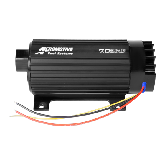
Part # 11197/11198
Product Description
INSTALLATION INSTRUCTIONS
WARNING!
WARNING!
WARNING!
WARNING!
CAUTION!
CAUTION:
.
Advertisement
Table of Contents

Related Manuals for Aeromotive 11197


Summary of Contents for Aeromotive 11197
- Page 1 AEROMOTIVE Part # 11197/11198 Product Description INSTALLATION INSTRUCTIONS This product is not legal for sale or use on emission-controlled vehicles except when used as a direct replacement part matching OEM specification. WARNING! Always be aware of flammable situations. Drilling and grinding can be potential ignition sources.
- Page 2 6. Using minimum of ¾” ID or AN-16 fuel line, connect the fuel tank sump outlet to a 100-micron fuel strainer (Aeromotive P/N 12362). Using the same size fuel line connect the fuel filter outlet to the fuel pump inlet or, if you are...
- Page 3 7. Using AN-16 fuel line, connect the fuel pump outlet to a 10 micron post fuel filter (Aeromotive P/N 12364). You can attach the filter directly to the fuel pump utilizing an AN-10 to ORB-16 fitting (Aeromotive P/N 15723) and an additional sealing o-ring (AN-10 o-ring pack Aeromotive P/N 15623).
- Page 4 Note: Be sure to route all electrical wires clear of any moving suspension or drivetrain components and any exhaust components! Protect wires from abrasion and road obstructions or debris. 9. Make sure you use stranded, insulated copper wire, in the sizes shown, with matching crimp-type connectors for all connections.
- Page 5 MODE 1 – TPS or Other 0-5VDC Input Control Aeromotive recommends the “Mode 1” control method where the 0-5VDC signal input is tied to a Throttle Position Sensor using the output wire to the ECU. The intent for this control is to reduce the fuel pump output (and thus the amount of returned fuel flow) during low throttle opening (low engine demand) to reduce excess recycling of fuel to help keep fuel tank temperatures low.
- Page 6 NOTE: When installing a new fuel system, the system will be contaminated from manufacturing and assembly. This contamination will be stopped by the Aeromotive P/N 12364 post filter. Change the post filter element after 100 miles or 2-5 run hours to ensure pump/system performance and service life (filter element part 12664).
- Page 7 AEROMOTIVE, INC. LIMITED WARRANTY This Aeromotive Product, with proof of purchase dated on or after January 1, 2003, is warranted to be free from defects in materials and workmanship for a period of one year from the original date of purchase.
Need help?
Do you have a question about the 11197 and is the answer not in the manual?
Questions and answers