Table of Contents
Advertisement
Quick Links
Advertisement
Table of Contents

Related Manuals for Aim-TTI SMU4000 Series


Summary of Contents for Aim-TTI SMU4000 Series
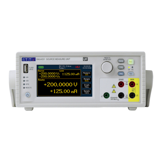
- Page 1 INSTRUCTION MANUAL SMU4000 SERIES SOURCE MEASURE UNITS...
-
Page 2: Table Of Contents
CONTENTS CONTENTS ................................1 Product description ............................. 4 Safety ................................5 Symbols ..................................5 Safety notices ................................. 6 Installation ..............................7 Mounting ..................................7 Ventilation ..................................7 Handle/stand .................................. 7 Electrical Requirements ..............................8 Switching On .................................. 9 Instrument overview ............................ 10 Front Panel ................................... - Page 3 Sequence mode ................................70 Digital I/O ............................... 77 Overview..................................77 Math Functions ............................79 Applying calculations to measurements ........................79 Measure..................................79 Result sorting ............................80 Tolerance ..................................80 Application notes ............................. 81 Source- Measure considerations ..........................81 SMU4000 Series Instruction Manual...
- Page 4 Routine Calibration ............................... 90 Factory Default settings .......................... 91 Specification ............................. 93 Specification Conditions ............................... 93 Key Specifications of SMU4000 series ......................... 93 Output Power, Voltage and Current Capability ......................96 Protection ..................................97 Measurement Result Buffer ............................97 Digital Input/Output (DIO) ............................. 98 Remote Control Interfaces ............................
-
Page 5: Product Description
SMU as the all-in-one solution for simplifying test applications such as battery charging/discharging, I-V characterising, semiconductor testing and much more. SMU4000 Series Instruction Manual... -
Page 6: Safety
European health, safety, and environmental Protective Earth terminal protection standards. Standby supply. Instrument is not disconnected from AC mains power when WEEE (do not dispose in household waste) switch is off. Alternating current. SMU4000 Series Instruction Manual... -
Page 7: Safety Notices
Do not use sharp or pointed objects to operate the touch screen. Take care not to restrict the inlet vents at the front, rear, sides or underneath the instrument. In rack-mounted situations, allow adequate space around the instrument. SMU4000 Series Instruction Manual... -
Page 8: Installation
Release the sides of the handle to lock it in the new position. SMU4000 Series Instruction Manual... -
Page 9: Electrical Requirements
Mains supply voltage selection: A switch is located in the highlighted postiton (SW1). Select the required value with the switch and replace the case. CAUTION The set AC input voltage MUST be clearly labeled on the rear panel. SMU4000 Series Instruction Manual... -
Page 10: Switching On
To fully disconnect from the AC supply, unplug the mains cord from the back of the instrument or switch off at the AC supply outlet; make sure that the means of disconnection is readily accessible. Disconnect from the AC supply when not in use. SMU4000 Series Instruction Manual... -
Page 11: Instrument Overview
The rotary knob is used to navigate the user interface and scroll through values - it features a ‘press’ function to select an option, see ‘Basic operation’ for more details. ⑤ Menu Keys HOME - Returns to the home screen, see ‘Home screen’ for more details. CNFG- Accesses the main menu configuration screen SMU4000 Series Instruction Manual... - Page 12 Ground- chassis ground for ground reference purposes only. See ‘Terminal selection’ for more details. ⑩ CV / CC LED indicator When the output is running, the CV/ CC indicators show whether the instrument is in Constant Voltage or Constant Current. SMU4000 Series Instruction Manual...
-
Page 13: Rear Panel
21Vpeak for SMU4001 or 210Vpeak for SMU4201 between HI & LO. F +/- [Force] - Force terminals source or sink voltage or current, they are permanently wired in parallel with the front panel Main HI and LO terminals. SMU4000 Series Instruction Manual... - Page 14 The DIO is an input/output port that receives, and outputs signals through digital I/O lines. See ‘Digital I/O’ for more details. +5.25Vpk Max. (diode clamped to +5V). The 5V supply is internally fused (resettable fuse) to 500mA, see the SMU4000 Series Service Manual for more information. SMU4000 Series Instruction Manual...
-
Page 15: Introduction
Other Manuals are available to download for this product series including: · Safety Documentation and Quick Start Guide [English, French, German, Italian & Spanish] · Programming Manual [English] · Service Guide [English] available on request. Available from www.aimtti.com/support. SMU4000 Series Instruction Manual... -
Page 16: Navigation Controls
② ① The Back button is available on sub menus, when pressed it will return to the previous menu. Back Button SMU4000 Series Instruction Manual... - Page 17 Revert- Revert the value back to the original; before the value was amended with the keypad. Rev Pol- Available when a positive or negative value is to be accepted, toggles between plus and minus symbol. A full QWERTY keyboard is available for text entry. SMU4000 Series Instruction Manual...
-
Page 18: Home Screen
When in Sequence mode the active step and operating mode will be shown. ④ Buttons: See ‘Measurement selection, ’Selecting a Range’, ‘Graph view Menu’ or ‘Sample table’ for more information. SMU4000 Series Instruction Manual... - Page 19 To access the High Voltage Interlock, the password protection may need to be removed first. Operating Voltage *SMU4201 Low Voltage Mode Limit * only. High Voltage Mode. ⑥Time Press to edit Time and Date and Date SMU4000 Series Instruction Manual...
-
Page 20: Getting Started
Hazardous voltages will appear on both sets of terminals. Always make connections to the instrument with the OUTPUT off and in the Open off state; this is the only output state that completely isolates the external circuitry from the instrument. SMU4000 Series Instruction Manual... -
Page 21: High Voltage Interlock [Smu4201 Only]
3. Remote interface control: The state of the interlock can be controlled directly without password protection. The status of the interlock can also be queried remotely. See the SMU4000 Series Programming Manual for more information. WARNING Enabling full voltage operation (asserting the interlock) could expose the user to potentially hazardous voltages that could result in injury or death. -
Page 22: Basic Operation
The default measurement period is 1 PLC. One Power Line Cycle (PLC) for 50Hz is 20ms and one PLC for 60Hz is 16.67ms. Mains input frequency is automatically monitored and applied by the instrument. SMU4000 Series Instruction Manual... - Page 23 A green digit indicates the encoder is in an active state, any adjustments using the encoder are live and will be actioned at the terminals immediately (when the SMU is running). · Double press the knob or press the HOME key to exit the live editing mode. SMU4000 Series Instruction Manual...
-
Page 24: Selecting A Range
Setting this to the lowest range that is required for the given test/application may help to reduce the settling time, as the lower ranges have generally longer settling times. SMU4000 Series Instruction Manual... - Page 25 3A range can only be accessed via manual range selection, the auto current range will stop at the 1A range. Noise pickup, leakage and instability issues may arise when testing within certain manual ranges, see ‘Application notes’ for tips to overcome these issues. SMU4000 Series Instruction Manual...
-
Page 26: Measurement Selection
The exported .CSV files contain all four measurement types. NOTE Alternative primary and secondary measurement types can be selected after the test is complete. The selected measurement data can be viewed in the sample table or the YT graph (primary measurements). SMU4000 Series Instruction Manual... -
Page 27: Saving Data
· System Time · Measurement Timestamp · Sequence Mode Step and Iteration NOTE To store all measurement data, the measurement buffer should be exported over remote or to an external flash drive after completion of each run (automatically). SMU4000 Series Instruction Manual... - Page 28 Buffered Data can be viewed in three different formats from the front panel: · Individually indexed measurements, see ‘Sample table’ for more details. · Graphically plotted data, see ‘Graph’ for more details. · Statistically, see ‘Measure Statistics’ for more details. SMU4000 Series Instruction Manual...
-
Page 29: Sample Table
Changing the primary and secondary measurements can be done live or even after the test is complete to access all four measurement data sets. SMU4000 Series Instruction Manual... -
Page 30: Measure Statistics
NOTE Changes to the primary and secondary measurements can be actioned live or even after the test is complete to access all four sets of measurement statical data (V, I, W & Ω). SMU4000 Series Instruction Manual... -
Page 31: Graph
CNFG > [Files] Graph HOME > Graph View Feature Auto-Scale • Auto-Fit • Graph Type • • Graph Style • • Minimum Position • • Markers • • Save/Load Trace • • Panning • Zooming • SMU4000 Series Instruction Manual... -
Page 32: Graph Menu
Select the graph type using the Voltammogram and YT Graph buttons positioned above the graph display. Pressing either the Voltammogram or YT Graph buttons will cause the graph to auto-scale; any NOTE manual scaling changes will be lost. SMU4000 Series Instruction Manual... - Page 33 Line (Default): Show the measured points connected in a linear format with a single line. Point: Show each measured point on the graph as a single pixel. Minimum position A minimum X and Y position can be defined, starting the plotted results at a defined point. SMU4000 Series Instruction Manual...
- Page 34 Pressing the Marker button whilst the marker is active will disable the movement of the marker via the encoder; however, the marker value and marker menu will still be displayed. This allows for selection switching between the two markers, only one marker position can be adjusted at any given time. SMU4000 Series Instruction Manual...
- Page 35 The loaded reference trace appears in blue on the same graph as the latest measurement trace. NOTE When recalling a trace, the graph auto-scale will ensure both the recalled trace and the latest measurement trace are visible on the display regardless of difference in levels. SMU4000 Series Instruction Manual...
- Page 36 Once selected a green outline will appear to show that the graph can now be moved either vertically or horizontally (dependant on selection). Use the encoder to pan the graph. Press the button again to disable the movement via encoder and return to navigation. SMU4000 Series Instruction Manual...
-
Page 37: Graph View Menu
Point or Line see ‘Graph Menu’ for more details on these functions. NOTE When a USB Flash Drive is present, screen captures of the graph can be stored by pressing the flash Drive symbol in the top left corner. SMU4000 Series Instruction Manual... -
Page 38: Storing And Loading Setup Files
The files stored on the Internal memory will take priority. If a USB flash drive is connected and internal max file limit is reached, no external files will be shown until an internal file is deleted. SMU4000 Series Instruction Manual... - Page 39 Store USB to export. To export a file, select the file to be transferred ①, once selected the file name will be The file will appear in the available setups list, with USB as the location. SMU4000 Series Instruction Manual...
- Page 40 Incompatible with the current firmware version or model. Red: Corrupted- Unable to be used or recovered. To load an arbitrary list of set levels for a sweep (.CSV), see ‘Loading a List’. To store buffer measurements (.CSV), see ‘Saving Data ’. SMU4000 Series Instruction Manual...
-
Page 41: Event Log
Selecting the Event Log symbol on the status bar will open the event log menu, this menu can menu, the events are colour coded and include a Warning or Error number alongside the time and date of when the error occurred. SMU4000 Series Instruction Manual... -
Page 42: Easy Setup
To activate a pre-configured setup, select the required option and press OK. If no option is Setup menu. selected, pressing OK will return to the Configuration menu and no change will be made. For more details, see SMU4000 Series Safety Documentation and Quick Start Guide, available to download from: www.aimtti.com/support. SMU4000 Series Instruction Manual... -
Page 43: Manual Setup
· ‘Math Functions’ When the manual setup is complete, it can be stored in non-volatile memory or exported via a USB Flash Drive using the Store Setup menu, see ‘Storing and Loading Setup’ for more details. SMU4000 Series Instruction Manual... -
Page 44: Operating Mode
· ‘Measure Voltage’ · ‘Measure Current’ · ‘Measure Resistance and High Resistance’ · ‘Sequence mode’ NOTE Changing the mode whilst the instrument output is running will disable the output to the given Off State defined for that mode. SMU4000 Series Instruction Manual... -
Page 45: Source Modes
The current source can be used to source and sink a constant current. Current, voltage, resistance and power can be simultaneously measured whilst sourcing current. The sourced current is constantly monitored and compared to the configured value, adjusting where necessary. SMU4000 Series Instruction Manual... -
Page 46: Load Modes
Implements I = V / R where R is the Level setting. The following sections give a brief description of the way each mode is implemented and give some guidance of the effect that has on the application of the load. SMU4000 Series Instruction Manual... - Page 47 This rapid change accentuates the effect of inductance in the interconnecting leads and can easily lead to bottoming and overshoots. Resistance mode is best used at higher voltages and modest currents. SMU4000 Series Instruction Manual...
- Page 48 As Load Power mode has the characteristics of a negative resistance, the possibility always exists of forming a negative resistance oscillator in combination with the output impedance of the external source. In practice, constant power mode normally operates well in conjunction with sources designed to supply such a load. SMU4000 Series Instruction Manual...
-
Page 49: Measure Modes
HI and LO SENSE sockets in addition to the MAIN HI and LO INPUT sockets. See Terminal s for more details. Because no significant current is flowing through the SENSE connections when utilising 4 wire measurement, contact resistance does not affect the measurement result. SMU4000 Series Instruction Manual... -
Page 50: Terminal Selection
HI. As such, if the MAIN HI is at a hazardous voltage, the same hazardous voltage level will also be present at the Guard. NOTE Specific Guard terminals only feature on the rear panel. The HI SENSE terminal can be used as a guard through the 2 wire plus guard terminal configuration. SMU4000 Series Instruction Manual... -
Page 51: Measurement Count
However, the 100k measurement buffer limit still applies, any measurements beyond this limit will be ignored. SMU4000 Series Instruction Manual... -
Page 52: Source Shape
· ‘Pulsed Sweep’ · ‘List’ Number of Shapes can be set when a shape waveform other than Steady is selected. The number of shapes defines the number of times a configured wave shape is sourced. This SMU4000 Series Instruction Manual... - Page 53 Manual Setup screen and the Home screen. When the output is enabled, “real-time” adjustments can be made from the Home screen, see ‘Live adjusting source and limits from the home screen’. ② ③ ① ④ ③ ① ② ④ SMU4000 Series Instruction Manual...
- Page 54 The measure delay shown in the following diagram shows a user defined measure delay. Alternatively an automatic settling delay can be selected. See ‘Timing options’ for more details. ③ ② ① ④ ⑤ ⑥ ③ ⑤ ① ② ④ ⑥ SMU4000 Series Instruction Manual...
- Page 55 The number of points in a dual sweep refers to the total number of points-from the start to the end and back to the start. When using a dual sweep, the total number of points must be an even number >=4 for dual, >=2 for single. SMU4000 Series Instruction Manual...
- Page 56 ‘Timing options’ for more details. ② ③ ① ④ ③ ① ② ④ The time it takes to complete one single sweep can be calculated by = (Number of Points x (Settling Delay + (Measurement Period x Measurement Count))). SMU4000 Series Instruction Manual...
- Page 57 In most situations there is very little use for the pulse sweep steady level results, as such the filter steady measurements option allows for the steady level measurements to be filtered out and discarded from the results buffer. SMU4000 Series Instruction Manual...
- Page 58 Only one measurement is made at each pulsed sweep steady level, regardless of the measurement count setting. When calculating pulse sweep timing take note that there is a settling time delay for both the sweep and steady level, however one delay setting covers both. SMU4000 Series Instruction Manual...
- Page 59 · Loaded from the Internal Memory. · Deleted from the Internal Memory. · Exported to a USB Flash Drive. NOTE SMU measurement data stored on a USB Flash Drive can be recalled as a list of points, once stored internally. SMU4000 Series Instruction Manual...
- Page 60 Recalling any stored list will override the existing configuration. To delete a List from the Internal Memory, select the required list, followed by Delete ③. A Delete a List from the Internal Memory pop-up box will appear to confirm the action. SMU4000 Series Instruction Manual...
-
Page 61: Output Off State
HV interlock, or the maximum allowable voltage for the SMU4001. Note that when the terminals are left open circuit the voltage may drift around significantly due to the very high input impedance. SMU4000 Series Instruction Manual... - Page 62 NOTE If measurements are enabled whilst the output is off, they will not appear in the measurement buffer, only on the home screen in the results box. SMU4000 Series Instruction Manual...
-
Page 63: Source Control
Enabling High Reactance mode can directly affect the instrument rise and settling times. Fastest instrument performance can only be achieved when High Reactance mode is disabled. High reactance mode can also lead to a noisier output and a slower response to changes in load due to reduced compensation. SMU4000 Series Instruction Manual... - Page 64 This is only possible if the Mode does not change between steps. In this particular situation the mode must remain the same for the next step to ensure the output remains active. SMU4000 Series Instruction Manual...
-
Page 65: Limits And Protection
(and predicting to exceed a limit) in order to enter the limit smoothly. Changing the limit in real time can also temporarily extend consequent source level change rise times. Ideally delay any source changes by 250ms after changing the limit, to maintain expected rise times. SMU4000 Series Instruction Manual... - Page 66 If one of the voltage, current or power trips occurs unexpectedly, this may be a result of instability, for information on how to overcome potential instability see ‘Application notes’. SMU4000 Series Instruction Manual...
-
Page 67: Source Level
Home screen or the Manual Setup menu. When the output is enabled, “real-time” adjustments can be made from the Home screen, see ‘Live adjusting source and limits from the home screen’. However, take note that in Steady shape, changing the source value will update instantaneously regardless of measurement counts. SMU4000 Series Instruction Manual... -
Page 68: Timing Options
When the off condition is set to Open, the relay switching delay is dealt with automatically and requires no additional measurement delay to cater for the relay switchover. However, a delay may still be required for allowing the source to settle. SMU4000 Series Instruction Manual... - Page 69 Matching and tracking the PLC measurement period to the exact mains frequency period will remove as much power line generated interference and noise as possible. The measurement period is a trade-off between measurement accuracy and measurement speed. SMU4000 Series Instruction Manual...
- Page 70 PIN 7 of the DIO port. This combination of global trigger in and trigger out allows for the handshaking of multiple instruments. For more information see ‘Digital I/O’. SMU4000 Series Instruction Manual...
-
Page 71: Sequence Mode
Each step must have a setup added, only one configuration setup can be added to each step. Select Setup and load a saved setup file to start the sequence to activate the Action and Condition options. ① ① SMU4000 Series Instruction Manual... - Page 72 8 - Manual setup Sequence mode Once a setup has been added, actions and conditions can be added to the sequence step. ① ② ③ ⑤ ⑥ ④ ⑦ ⑧ ② ⑧ ① ③ ④ ⑤ ⑥ ⑦ SMU4000 Series Instruction Manual...
- Page 73 Jump to step - Jump to a pre-defined step or next step in the sequence. DIO output level - Set DIO output pin as Logic High [5V] or Logic low [0V] Stop – Stop the sequence Repeat This will repeat the entire step a set number of times. SMU4000 Series Instruction Manual...
- Page 74 If triggering via remote command, the commands are as follows: SYST[em]:TRIG[ger] = Global Trigger within a setup, used to trigger a level or shape. *TRG = Sequence Trigger can be used to start a sequence, or assigned as a condition to initiate an action. SMU4000 Series Instruction Manual...
- Page 75 The SMU will set the assigned DIO output pins to either Logic High [5V] or Logic Low [0V] before the main setup is run. Step 1 can be set High or Low, step 2 onwards can be set to Ignore, High or Low. SMU4000 Series Instruction Manual...
- Page 76 Any trip caused by OVP/OCP/OPP will cause the entire sequence to stop. If a sequence is interrupted (satisfied stop condition, manually disabling the output or a trip/protection event) a message will appear in the event log. SMU4000 Series Instruction Manual...
- Page 77 NOTE The total number of measurements recorded cannot exceed 100,000. The sequence will continue to run when the measurement buffer is full, however no measurements will be recorded. SMU4000 Series Instruction Manual...
-
Page 78: Digital I/O
For safety reasons, test fixtures that may contain hazardous voltages often utilize a safety cover, a form of lid or even complete enclosures to protect the user from hazardous voltage exposure. SMU4000 Series Instruction Manual... - Page 79 HV Interlock Additional +5V and 0V lines are provided for powering external control circuitry. The 5V supply is internally fused (resettable fuse) to 500mA, see the SMU4000 Series Service Manual for more information. Set direction to Input to allow an external device to control the state of the line.
-
Page 80: Math Functions
B is an offset value that can either be set as a user specified custom value or a live reference point. Measure CNFG > [Source Measure Action] Manual Setup > [Results] Measure The Math Measure configuration selects which measurement the math operation will be applied to. SMU4000 Series Instruction Manual... -
Page 81: Result Sorting
If the measurement is above or below the set limit, the results screen will display T FAIL above the relevant measurement result. Pass and fail results will be available to view in the saved .CSV file. See Saving Data SMU4000 Series Instruction Manual... -
Page 82: Application Notes
Utilize the front panel ground chassis connection as a shield, however this is unlikely to be as effective as the MAIN LO terminal. • Turn off/ route cables away from any known noise sources within the environment. SMU4000 Series Instruction Manual... - Page 83 Setting a limit too close to the desired output level can result in extended source rise/fall times. The source is slewed slightly when approaching (and predicting to exceed a limit) in order to enter the limit smoothly. SMU4000 Series Instruction Manual...
-
Page 84: Powerflex
Absolute voltages above |21V| are only achievable on the SMU4201. Maximum Voltage and Current capabilities: SMU4001 & SMU4201 0V to 20V Voltage(±) Current(±) 2.5A 2.08A 1.25A SMU4201 21V to 200V Voltage(±) Current(±) 0.5A 0.5A 100V 0.25A 120V 0.208A 150V 0.167A 180V 0.139A 200V 0.125A SMU4000 Series Instruction Manual... -
Page 85: System Management
· S/M Settings - Restricted access for all Source and Measurement settings. This menu. changes to the Source Measure Action ① and System ② menus. · All Settings - Restricted access to all Configuration settings. This includes any ① ② SMU4000 Series Instruction Manual... - Page 86 · Initially On- Immediately powers the instrument on when the AC mains in connected, manual power control will remain functional after the initial power · Always On- Whilst AC mains is connected, the standby switch will perform a reset when pressed. SMU4000 Series Instruction Manual...
- Page 87 Do not delete or change any of the files inside the “UPDATE” folder prior to a firmware update. Configuration & Info Default settings - sets all configuration data to default, see ‘Factory Default settings’ for more details. System Info - Displays the Manufacturer, Model, Serial number, Firmware Version numbers and calibration status. SMU4000 Series Instruction Manual...
- Page 88 To put the SMU into recovery mode, hold the HOME key and press the standby button (when the SMU is powered OFF) until recovery mode is enabled. To exit recovery mode, switch off the instrument in the usual way using the standby button. SMU4000 Series Instruction Manual...
-
Page 89: Maintenance
If the instrument requires cleaning, use a cloth that is only lightly dampened with water or a mild detergent. WARNING To avoid electric shock, or damage to the instrument, never allow water to get inside the case. To avoid damage to the case never clean with solvents. SMU4000 Series Instruction Manual... -
Page 90: Remote Interfaces
This includes configuration options for LAN, USB and GPIB (where fitted). This menu also provides the status information of any of the digital remote interfaces that are connected to the instrument. For more information on Remote Interface configuration, see ‘SMU4000 Series Programming Manual’, available to download from www.aimtti.com/support... -
Page 91: Calibration
The Calibration menu provides access to all of the instrument calibration routines. The external calibration routines require accurate measurement equipment for measuring ultra- precise DC voltages and currents. This menu is password protected; the password can be found in the SMU4000 Series Service Guide, available upon request from www.aimtti.com/support WARNING Routine Calibration should only be carried out by qualified service personnel. -
Page 92: Factory Default Settings
High Reactance Measurement Control Disabled Disabled Disabled Math None Sorting None Graph Type YT Graph Style Line X Axis Minimum Position 0 Seconds Y Axis Minimum Position X Axis Scale 200µs/div Y Axis Scale 20nV/div Markers Disabled SMU4000 Series Instruction Manual... - Page 93 17 - Factory Default settings Routine Calibration System High Voltage Interlock * Brightness Auto-Dim Beeper Power Control Manual On/Off Air Vents Clear *SMU4201 only SMU4000 Series Instruction Manual...
-
Page 94: Specification
Ambient temperature change of less than ± 3°C after self-calibration and measurement zero. Calibration Period: 1 Year Temperature: 23°C ± 5°C Measurement Period: ≥10 PLC Key Specifications of SMU4000 series SMU4001 SMU4201 Maximum Voltage ±21V ±210V Voltage ranges 20mV – 20V 20mV –... - Page 95 18 - Specification Key Specifications of SMU4000 series Measurement Supplementary Characteristics User settable 200µs to 20s (10µs resolution), or 0.01 to 100PLC (0.001PLC resolution) If set to integer PLC: synchronized to actual mains supply period Measurement Period Accuracy: ± (50µs + 0.01%) Typically, <±0.5µs delay between measured Voltage and Current...
- Page 96 18 - Specification Key Specifications of SMU4000 series Voltage Source (SV and MHR modes) Accuracy Same as voltage measurement accuracy SMU4001 ±21V Source Limit ⁴ SMU4201 ±210V SMU4001 User settable 21V/s to 120V/ms Maximum Slew Rate SMU4201 User settable 210V/s to 1.2V/µs To reach within 0.5% of change, open load, max slew rate,...
-
Page 97: Output Power, Voltage And Current Capability
3A current limit, limits power at absolute voltages < |8.33V|. Absolute voltages above |21V| are only achievable on the SMU4201. Output current limited to 0.5A at absolute voltages > |21V|. SMU4000 Series Instruction Manual... -
Page 98: Protection
Index Active Mode Output state Measurement results (V and A) .CSV file contents Calculated results (R and W) System Date System Time Measurement Timestamp Sequence Mode Step and Iteration Length Maximum of 100000 entries, FIFO style SMU4000 Series Instruction Manual... -
Page 99: Digital Input/Output (Dio)
Conforming with IEEE488.1 and IEEE488.2 Typically < 5ms between receiving the command terminator Remote Command for an output change at the instrument and the output Processing Time beginning to change. System Speeds Measure to Memory Up to 5k/s sustained SMU4000 Series Instruction Manual... -
Page 100: Environmental
Size (nominal) Rack Mount: 213.5mm(W) (½ rack) x 86.5mm(H) (2U) x 269mm(D) Weight (nominal) 4.25kg Aim & Thurlby Thandar Instruments Ltd. operates a policy of continuous development and reserves the right to alter specifications without prior notice SMU4000 Series Instruction Manual... - Page 101 EXCELLENCE THROUGH EXPERIENCE Aim-TTi is the trading name of Thurlby Thandar Instruments Ltd. (TTi), one of Europe’s leading manufacturers of test and measurement instruments. The company has wide experience in the design and manufacture of advanced test instruments and power supplies built up over more than thirty years.
Need help?
Do you have a question about the SMU4000 Series and is the answer not in the manual?
Questions and answers