Table of Contents
Advertisement
Quick Links
Advertisement
Table of Contents

Related Manuals for Aim-TTI tf930


Summary of Contents for Aim-TTI tf930
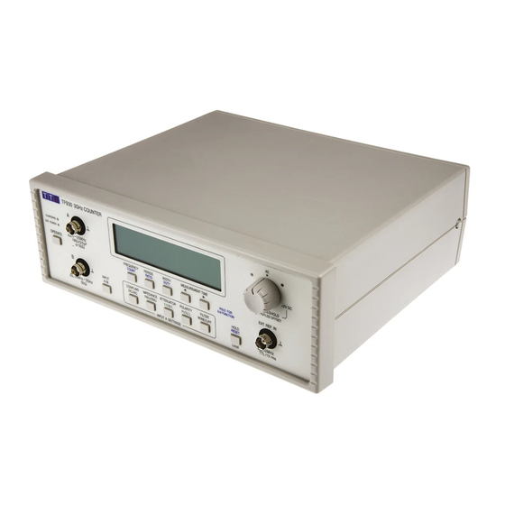
- Page 1 TF930 3GHz Universal Counter INSTRUCTION MANUAL...
-
Page 2: Table Of Contents
Remote Operation Maintenance Introduction The TF930 is a portable, battery-operated, universal counter with a large 0.5" 10-digit liquid crystal display (LCD). The frequency range is from below 0.001Hz to 3GHz and measurement functions include frequency, period, ratio, pulse width and count. -
Page 3: Specification
Specification Input Specifications Input A Configurable options Input coupling: AC or DC Input impedance: 1MΩ or 50Ω Attenuation: 1:1 or 5:1 Active edge: Rising or falling, or width high or low Low pass filter: Filter In (~50kHz cut-off) or Out Trigger threshold: Variable threshold for both DC and AC coupling Input Impedance:... -
Page 4: Measurement Functions
Timebase Measurement Clock: 50MHz. Internal Reference oscillator: 10MHz TCXO with electronic calibration adjustment. Oscillator Temperature Stability: Better than ± 1ppm over rated temperature range. Initial Oscillator Adjustment Error: < ± 0.2ppm at 21ºC. Oscillator Ageing Rate: < ± 1ppm first year. Calibration adjustment range: >... -
Page 5: Remote Control
Operating Facilities Noise Filter The Filter key controls a low pass filter, with a cut-off frequency of about 50kHz, to assist in obtaining stable readings at low frequencies. Hold Pressing the Hold key will hold the current measured value in the display, with the Hold indicator on, until the Hold key is pressed again. -
Page 6: Safety
Safety Universal Counter This instrument is Safety Class III according to IEC classification and has been designed to meet the requirements of EN61010-1 (Safety Requirements for Electrical Equipment for Measurement, Control and Laboratory Use). This instrument has been tested in accordance with EN61010-1 and has been supplied in a safe condition. -
Page 7: Connections
Connections Front Panel Connections Input A For frequencies in the range 0.001Hz (DC coupled) to >125MHz. Input impedance selectable between 1MΩ//25pF and 50Ω. Maximum allowable input 1V (1:1 attenuation) or 4V (5:1 attenuation) for 1MΩ//25pF input; 1V above 300kHz for 50Ω input (AC coupled). Maximum input with respect to earth ground is 30V or 30V... -
Page 8: Manual Operation
Power-up and power-down operation for all possible combinations of conditions are detailed in the sections that follow. Safety Warning: The TF930 is a safety class III instrument by IEC classification. When the instrument is operated from its internal battery, AC adaptor or USB port of a portable (ungrounded) PC, all accessible parts will be at the same voltage potential as the outer of the BNC input sockets;... - Page 9 AC Adaptor Operation The AC adaptor is connected to the rear panel 1.3mm socket marked DC IN; only the AC adaptor supplied with the instrument should be used. When the AC adaptor is powered the red EXT POWER lamp will be lit, whether the instrument is on or off; if the battery is being charged the yellow CHARGING lamp will also be lit.
- Page 10 Input A Configuration Options The default configuration options for Input A at power-on are: AC coupling, 1MΩ input impedance, 1:1 attenuation, rising edge polarity and no filter; with the Threshold control set to mid-position a measurement should be possible with the majority of waveforms. Changes to the configurations will, however, be necessary for certain waveforms, e.g.
- Page 11 This setting should count most signals, but on very small signals some slight adjustment may be needed for maximum sensitivity. The usable adjustment range from this position is approximately ±50mV (1:1 attenuation) or ±200mV (5:1 attenuation). If DC coupling is in use then the feedback mechanism is disconnected and the threshold is directly adjusted by the control over the range of nominally 0 to 2V (1:1 attenuation) or 0 to10V (5:1 attenuation).
- Page 12 Function Selection – B input With Input B (80MHz – 3GHz) selected only the FREQUENCY and PERIOD functions can be used; attempts to select WIDTH, COUNT or DUTY will be ignored by the firmware; the annunciator will flash briefly to indicate that this is not a valid selection and the existing setting will remain unchanged.
- Page 13 If the signal has frequency modulation the instrument will display the average value across the gate time; the modulation is almost certainly not synchronous with the gate, so there will be small random variations in the displayed value. If the signal has amplitude modulation, its amplitude at the trough of the modulation must exceed the sensitivity threshold of the input.
- Page 14 Noise When measuring low amplitude, low frequency sinewaves noise will cause variations in the displayed result at each display update. Users should make every effort to maximise the amplitude of the signal presented to the input. The internal noise of the instrument is random, with a significant low frequency (1/f) element.
-
Page 15: Remote Operation
Windows applications in exactly the same way as a standard port. If it is anticipated that more than one TF930 might be connected to the same PC it is recommended that the drivers be copied first to a suitable location on the hard disc and then installed from there when the first unit is attached. - Page 16 Remote Command Format Serial input to the instrument is buffered in an input queue which is filled, under interrupt, in a manner transparent to all other instrument operations. The instrument will send XOFF when the queue is nearly full; XON will be subsequently be sent when sufficient space becomes available for more data to be received.
- Page 17 Low frequency mode. Applicable to TF830 only. Command accepted but ignored by TF930, which is automatically in low frequency mode while DC coupling is selected.
- Page 18 Threshold Level to centre position. Threshold Level to negative pulse position. Threshold Level to positive pulse position. These three commands are only included to maintain compatibility with the TF830 and are used to set the threshold level to one of three ‘preset’ positions available under remote control on that counter. ‘Centre’ is equivalent to the threshold level control at the midway 'AC' position.
- Page 19 Miscellaneous Commands *IDN? Returns the instrument identification in the form <name>, <model>, 0, <version><rmt> where <name> is the manufacturer’s name, <model> is the type of instrument and <version> is the revision of the firmware installed. Identify Query. Returns the instrument model number only. *RST Resets the instrument to its power-on default values and sets the Threshold Level to the midway ‘AC' position.
- Page 20 A input 1MΩ input impedance. A input 50Ω input impedance. A input 1:1 attenuator. A input 5:1 attenuator. Rising edge (A Input only). Falling edge (A Input only). Filter In (A Input only). TF830 Filter Out (A Input only). TF830 Low frequency mode.
-
Page 21: Maintenance
Maintenance The Manufacturers or their agents overseas will provide a repair service for any unit developing a fault. Where owners wish to undertake their own maintenance work, this should only be done by skilled personnel in conjunction with the Service Information available from the Manufacturers or their agents overseas. - Page 22 Thurlby Thandar Instruments Ltd. Glebe Road • Huntingdon • Cambridgeshire • PE29 7DR • England (United Kingdom) Telephone: +44 (0)1480 412451 • Fax: +44 (0)1480 450409 International web site: www.aimtti.com • UK web site: www.aimtti.co.uk Email: info@aimtti.com Book Part No. 48581-1400 Iss 8 Aim Instruments and Thurlby Thandar Instruments...
Need help?
Do you have a question about the tf930 and is the answer not in the manual?
Questions and answers