
Related Manuals for ITech IT8912E

Summary of Contents for ITech IT8912E
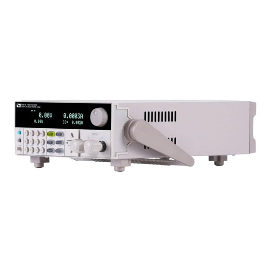
- Page 1 Programmable DC Electronic Load IT8912E User’s Manual Model: IT8912E Version: V2.0...
- Page 2 “Caution” signs indicate danger. It is extent of laws, ITECH is not committed languages of other countries or regions) required to pay attention to the contents to any explicit or implied guarantee for...
-
Page 3: Limitation Of Warranty
ITECH, and ITECH will be responsible for return freight. ⚫ If the product is sent to ITECH for warranty service from other countries, the customer will be responsible for all the freight, duties and other taxes. Limitation of Warranty... -
Page 4: Safety Precautions
In case of failure to follow these precautions or specific warnings in other parts of the manual, violation against the safety standards related to the design, manufacture and purpose of the instrument will occur. If the user does not follow these precautions, ITECH will bear no responsibility arising there from. ⚫... -
Page 5: Regulation Tag
According to the equipment classification in Annex I of the WEEE directive, this instrument belongs to the “Monitoring” product. If you want to return the unnecessary instrument, please contact the nearest sales office of ITECH. Copyright ©ITECH Electronic Co., Ltd. -
Page 6: Compliance Information
Connection of the instrument to a test object may produce radiations beyond the specified limit. Use high-performance shielded interface cable to ensure conformity with the EMC standards listed above. Safety Standard IEC 61010-1:2010/ EN 61010-1:2010 Copyright ©ITECH Electronic Co., Ltd. -
Page 7: Table Of Contents
3.16 Measurement rise time For voltage ......................... 31 3.17 VON function ..............................31 3.18 Protective function ............................33 3.18.1 Overvoltage protection (OVP) ......................33 3.18.2 Overcurrent protection (OCP) ......................33 3.18.3 Overpower protection (OPP) ....................... 34 Copyright ©ITECH Electronic Co., Ltd. - Page 8 References of Load Communication Interfaces ................42 5.1 RS232 interface..............................42 5.2 USB Interface ..............................43 5.3 GPIB interface (Only for IT8912E(G)) ........................44 Appendix ................................45 Specifications of Red and Black Test Lines ........................ 45 Copyright ©ITECH Electronic Co., Ltd.
-
Page 9: Chapter1 Acceptance And Installation
The package requirements should be met when the instrument is returned to factory for repair. IT8912E electrical load has optional fittings for individual sales. Detailed descriptions of each fitting are as shown below: Device name... -
Page 10: Adjustment Of Load Handle
Detailed dimensional drawings 1.3 Adjustment of load handle IT8912E load is equipped with a handle for user to easily carry and place it. The load handle can be adjusted based on the three methods shown below. When adjusting the handle, gently pull the handle towards two sides and then rotate the handle. -
Page 11: Disassembly Of Load Handle
Do not use too much force and mind your hands during disassembly of load handle. 1.5 Rackmount Installation This instrument can be installed on standard 19-inch rack. ITECH provides user with IT-E151/IT-E151A rack, as an optional mount kit. The detailed operation, please refer to the User Manual of your mount kit. -
Page 12: Connecting Test Lines (Optional)
⚫ Always use test lines provided by ITECH to connect the equipment. If test lines from other factories are used, please check that the test line can withstand maximum current. -
Page 13: Chapter2 Quick Start
Start Chapter2 Quick Start This chapter will introduce power-on check steps of IT8912E to ensure normal start-up and usage under initialization status of the load. Besides, to facilitate usage, this part also displays the functions of front board, rear board and... - Page 14 Quick Start NOTE IT8912E(G) is the model with built-in GPIB, the function is the same as standard model, please check with ITECH for availability. Copyright ©ITECH Electronic Co., Ltd.
-
Page 15: Front Panel Introduction
⑤ Function key:set the operation mode;Control the input state:on/off ⑥ direction key:to toggle the menu items,move the cursor location ⑦ input terminal 2.3 Introduction of keyboard Keys at IT8912E key area are shown below. Detailed description of keys: keys Name and functions This key is used to enter other menus and functions. -
Page 16: Fast Function Key
Left/Right key, to adjust the cursor to the specified location to set the value . 2.4 Fast function key A combination of front board keys and Shift composition keys in IT8912E can realize functions marked at key bottom. For details, see table below. keys Name and functions To start or end short circuit test. -
Page 17: Function Description Of Vfd Status Indicators
2.6 Rear panel Introduction ① Heat radiating window ② RS232 communication interface ③ USB communication interface ④ GPIB communication interface(Only for IT8912E(G)) ⑤ Remote sense,external trigger,external analog control terminal (0-10V),PWM output terminal ⑥ External signal control terminal ⑦ I-monitor terminal ⑧... - Page 18 Before operation, please confirm that you have fully understood the safety instructions. ⚫ IT8912E electronic load supports 110V or 220V AC input methods. Before powering on, be sure to check that the AC input switch status matches with the supply voltage. Otherwise, it may damage the electronic load.
- Page 19 See the table blow for matching information of fuse and machine model. Product Fuse specification(220VAC) Fuse specification(110VAC) IT8912E 2.5AT 1.25AT 3) After replacement, install the fuse box back to original position, as shown below. Copyright ©ITECH Electronic Co., Ltd.
-
Page 20: Chapter3 Function And Features
Constant power operation mode (CW) Constant current operation mode (CC) 3.2.1 Under CC mode, the electronic load will consume constant current in regardless of whether the input voltage changes or not, as shown in Fig. 3-1. Copyright ©ITECH Electronic Co., Ltd. - Page 21 Constant Current ▼ High-Rate Low-Rate Set ascending slope and press [Enter] key. Constant Current ▼ Rise up=0.001A/uS Set descending slope and press [Enter] key. Constant Current Rise down=0.001A/uS Complete parameter setting. 10.0000V 0.0000A 0.00W CC=1.000A Copyright ©ITECH Electronic Co., Ltd.
-
Page 22: Constant Voltage Operation Mode (Cv)
Set maximum current value and press [Enter] key. Constant Voltage ▲High=15.000A ▼ Set minimum current value and press [Enter] key. Constant Voltage ▲Low=0.0000A ▼ Set high and low rate and press [Enter] key. Constant Voltage ▲High-Rate Low-Rate Complete parameter setting. Copyright ©ITECH Electronic Co., Ltd. -
Page 23: Constant Resistance Operation Mode (Cr)
Constant power operation mode (CW) 3.2.4 Under CW mode, the electronic load will consume a constant power, as shown below. If input voltage rises, the input current decreases and power P (= V * I) Copyright ©ITECH Electronic Co., Ltd. -
Page 24: Input Control Function
VFD Off is On and the input is off. When the electronic load is on, the VFD working status indicator is OFF. 3.4 Keyboard locking function Press the composite key (Shift)+ (Lock) to lock the instrument board key, and the VFD displays *. Under other function statuses, except Copyright ©ITECH Electronic Co., Ltd. -
Page 25: Short-Circuit Analog Function
Set parameters and press [Shift]+ 4 keys to save data. Press 9 key (to select in which group the data is to be saved). 5.8949V 0.99994A 5.89W SAVE 9 Press [Enter] key. 5.8949V 0.99994A 5.89W cc=1.000A ⚫ RECALL Copyright ©ITECH Electronic Co., Ltd. -
Page 26: System Menu Function (System)
Select the USB communication interface. GPIB Address(0-31) PROTOCOL Communication protocol selection SCPI protocol SCPI(Default) Protocol Extend-Table Expand SCPI protocol for compatibility of other machines 3.8 Configuration menu function (Config) Press [Shift] + 9 to enter menu configuration (CONFIG MENU). Copyright ©ITECH Electronic Co., Ltd. -
Page 27: Trigger Function
TRIG will generate trigger signals and low pulse is effective. An input corresponding to each trigger can be used to change set value (voltage, current, resistance, etc). Copyright ©ITECH Electronic Co., Ltd. -
Page 28: List Operation
7 groups of list files at maximum. If the load operation mode is at List operation, the load will start List operation when it receives a trigger signal and will stop when it complete or when it receives another trigger signal. Copyright ©ITECH Electronic Co., Ltd. - Page 29 Edit slope in step 2 and press [Enter] key. EDIT LIST Step 002 Rate=0.1A/uS 10. Edit time in step 2 and press [Enter] key. EDIT LIST Step 002 Width=5S 11. Edit repeat count and press [Enter] key. Copyright ©ITECH Electronic Co., Ltd.
-
Page 30: Dynamic Test Function
The dynamic test mode can be divided into continuous mode, pulse mode and toggle mode. Continuous mode 3.11.1 Under continuous mode, after enabling dynamic test operation, the load will be switched continuously between A value and B value. Copyright ©ITECH Electronic Co., Ltd. - Page 31 Level B=2A Set frequency value and press [Enter] key. TRANSITION Frequnce=50Hz(0.01-25000Hz) Set duty ratio and press [Enter] key. TRANSITION Duty=98%(0.1%-99.9%) 10. Start dynamic test and operate key. Move to On and press [Enter] key. TRANSITION Copyright ©ITECH Electronic Co., Ltd.
-
Page 32: Pulse Mode
Set ascending slope and press [Enter] key. TRANSITION Rise up=30.000A/uS Set descending slope and press [Enter] key. TRANSITION Rise down=30.000A/uS Set A value and press [Enter] key. TRANSITION Level A=1A Set B value and press [Enter] key. TRANSITION Level B=2A Copyright ©ITECH Electronic Co., Ltd. -
Page 33: Toggle Mode
TRANSITION Continuous Pulse Toggle Operate key and select high range and low range. Move to the High-Rate and press [Enter] key. TRANSITION High-Rate Low-Rate Set ascending slope and press [Enter] key. TRANSITION Copyright ©ITECH Electronic Co., Ltd. -
Page 34: Ocp Test Function
3.12 OCP test function The IT8912E electronic load is provided with overcurrent protection test function (OCP). Under OCP test mode, when input voltage reached Von value, delay for a while for the electronic load to latch. Ascend value by step value at regular interval. -
Page 35: Opp Test Function
Set cutoff power value 7:End Power=0.000W Set OPP voltage value 8:OPP Voltage=0.000V Set overpower range 9:Max Trip Power =0.000W (maximum value) Set overpower range 10:Min Trip Power =0.000W (minimum value) Save OPP test Save OPP File=1(1-5) documents Copyright ©ITECH Electronic Co., Ltd. -
Page 36: Battery Discharge Test Function
STOP 3.14 Battery discharge test function In the IT8912E electronic load, constant current mode is applied for discharge test with programmatic setting of stop voltage/capacity/discharging time If stop voltage is set as the stop condition, the system determines whether the battery is about to reach the set threshold value or unsafe status when the battery voltage is low, and if yes, an automatic stop will be activated. -
Page 37: Cr-Led Test Function
CR mode. Only when the voltage across the electronic load is higher than the diode break-over voltage, the electronic load will work. This is the completely true simulation of the working principle of the diode. So IT8912E electronic load can simulate the real LED test ripple current. - Page 38 0.01~1 0.08~30Ω 0.1~500V 0~3A 0.01~1 1.8~1600Ω The relationship among Vo, Io, Rd and Coeff shall be subject to the equation: oeff . Actual set values of Vo, Io and Coeff are affected by their Copyright ©ITECH Electronic Co., Ltd.
-
Page 39: Measurement Rise Time For Voltage
0.08 to 1. The user cannot set any value between 0.01 and 0.08. 3.16 Measurement rise time For voltage The IT8912E electronic load is provided with special voltage rise/drop time measurement function. This function gives a simple analog of voltage rise/drop speed of oscilloscope test power. - Page 40 When VON LATCH function is started, the load starts load test only when the power voltage rises and is higher than Von Point loading voltage. When the power voltage drops and is lower than Von Point unloading voltage, the load will not unload. Copyright ©ITECH Electronic Co., Ltd.
-
Page 41: Protective Function
When the hardware triggers overcurrent protection, OC bit of the status register will be set; when such protection is removed, the OC bit will be reset. The On/Off status of load will not be changed by the hardware Copyright ©ITECH Electronic Co., Ltd. -
Page 42: Overpower Protection (Opp)
3.19 Functions of the terminals at the rear panel Remote sense compensation functions 3.19.1 Under CC, CV, CR or CP mode, if the load consumes large current, a large voltage drop will be detected in connection line between tested instrument and Copyright ©ITECH Electronic Co., Ltd. -
Page 43: External Trigger Function
EXT PRG terminal to analog input from 0- full range so as to adjust input voltage and current of load (10V corresponds to voltage or current of load at full range). Voltage fault indication 3.19.4 When load is under overvoltage protection or terminal reverse polarity Copyright ©ITECH Electronic Co., Ltd. -
Page 44: Current Monitoring (I Monitor)
3.20 Auto test function The IT8912E electronic load delivers strong auto test functions, which can analog several tests. A total of 10 groups of test files can be edited, and each group test file has 10 steps. Therefore, a maximum of 100 steps can be edited and saved in EEPROM. - Page 45 14. Save the programmed files in EEPROM. A total of 10 groups of files can be saved. If it is to save edited files in group 1, press 1 key. Press [Enter] key. PROGRAM Save Program File=1(1-10) 15. Press [ESC] key to exit editing menu. Copyright ©ITECH Electronic Co., Ltd.
- Page 46 Run and press [Enter] key. PROGRAM Recall Edit Display auto test file 1. PRG01 STOP Press [Shift] + key. Operate auto test file 1. Press [Shift] + 0 key to pause auto test. Press key for next step. Copyright ©ITECH Electronic Co., Ltd.
-
Page 47: Chapter4 Technical Specification
Frequency range 20Hz~2KHz Duty cycle 10%~100% Measurement range range 0~500V Readback resolution 10 mV voltage accuracy ±(0.025%+0.025%FS) range 0~3A 0~15A Readback resolution 0.01mA 0.1mA current accuracy ±(0.05%+0.05%FS) range 300W Readback resolution 10mW power accuracy ±(0.2%+0.2%FS) Copyright ©ITECH Electronic Co., Ltd. -
Page 48: Supplementary Parameters
*The above specifications may be subject to change without prior notice. 4.2 Supplementary parameters Memory capacity:100 groups Suggested calibration frequency:1time/year Input levels of AC power supply (which can be selected through the switch at load bottom) Option Opt.1: 220V ±10% 50Hz/60Hz Copyright ©ITECH Electronic Co., Ltd. - Page 49 Technical Specification Option Opt.2: 110V ±10% 50Hz/60Hz Cooling method: Fan cool Copyright ©ITECH Electronic Co., Ltd.
-
Page 50: Chapter5 References Of Load Communication Interfaces
Modem cable. NOTE IT8912E has two COM ports at the rear panel: The 9-hole COM port connectors at top are the RS232 communication ports; and the 9-pin COM ports at bottom are the external signal control interfaces. -
Page 51: Usb Interface
All functions of the load can be programmed via USB. The functions of load USB488 interface are as follows: ⚫ The interface is 488.2 USB488 Interface. ⚫ The interface receives requests of REN_CONTROL, GO_TO_LOCAL and LOCAL_LOCKOUT. Copyright ©ITECH Electronic Co., Ltd. -
Page 52: Gpib Interface (Only For It8912E(G))
RL1 enabled. ⚫ DT1 enabled. 5.3 GPIB interface (Only for IT8912E(G)) Firstly, connect load GPIB interface and computer GPIB card through IEEE488 bus and ensure sufficient contact. Tighten them with screws. Set address. Load address range: 0-31. Press [Shift] + numeric key 8 (System) to enter system menu functions. -
Page 53: Appendix
Specifications of Red and Black Test Lines ITECH provides you with optional red and black test lines, which individual sales and you can select for test. For specifications of ITECH test lines and maximum current values, refer to the table below. - Page 54 Contact Us Thanks for purchasing ITECH products. In case of any doubts, please contact us as follows: 1. Visit ITECH website: www.itechate.com. 2. Select the most convenient contact method for further information.
Need help?
Do you have a question about the IT8912E and is the answer not in the manual?
Questions and answers