
Related Manuals for Delta VIVOTEK SUPREME MA9322-EHTVL


Summary of Contents for Delta VIVOTEK SUPREME MA9322-EHTVL
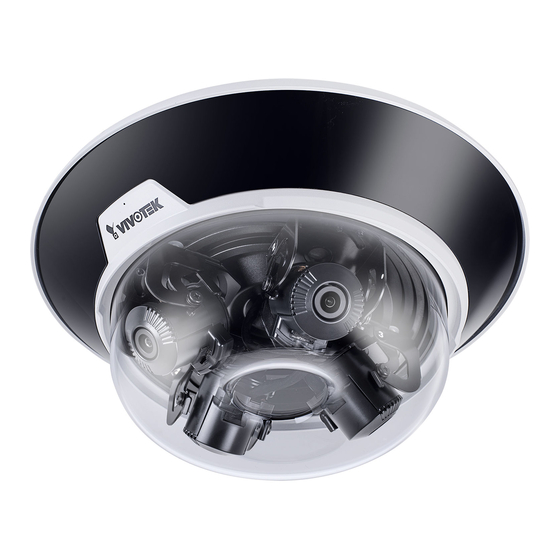
- Page 1 MA9322-EHTVL Panoramic Multi-sensor Network Camera User ’s Manual 20MP • 360° Surround View • IP66 • IK10 • Remote Focus • SNV Smart Stream III • PoE • -40°C ~ 60°C Wide Operating Temperature Rev. 1.0...
-
Page 2: Table Of Contents
VIVOTEK Table of Contents Overview ..................................Revision History ..............................3 Read Before Use ..............................4 Package Contents .............................. 4 Symbols and Statements in this Document ......................8 Physical Description ............................... 8 Mounting Options ..............................12 Ceiling Mount ............................... 14 Software Installation ............................. 23 Network Deployment ............................ -
Page 3: Overview
VIVOTEK Recording > Recording settings ......................164 Storage ..............................169 Storage > SD card management ......................169 Storage > NAS management ........................170 Storage > Content management ......................172 Technology License Notice ........................176 Electromagnetic Compatibility (EMC) ....................... 177 Overview The new MA9322-EHTVL is the most versatile product offering to date from VIVOTEK. -
Page 4: Read Before Use
VIVOTEK Read Before Use The use of surveillance devices may be prohibited by law in your country. The Network Camera is not only a high-performance web-ready camera but can also be part of a flexible surveillance system. It is the user’s responsibility to ensure that the operation of such devices is legal before installing this unit for its intended use. - Page 5 VIVOTEK セキュリティ基準(新規則第34条の10) 「本製品は 電気通信事業者(移動通信会社、固定通信会社、インターネットプロバイダ 等)の通信回線(公衆無線 LAN を含む ) に直接接続することができません。本製品をインターネットに接続する場合は、必ずルー タ等を経由し接続してください。」 NOTE: Camera Hardware Preventative Maintenance: 1. Visual inspection of all major components including accessories, cabling and connections where accessible for signs of deterioration or damage. 2. Check and clean cameras, lenses and housings inside and out as needed. •...
- Page 6 VIVOTEK IMPORTANT: The product shall be grounded properly with a screw type of 3.5mm min. for protective earthing terminal, and connected using a green-yellow protective earthing conductor with 20 AWG min. IMPORTANT: 1. The product must be installed and protected in a location that is not easily accessible, and is away from impacts or heavy vibration.
- Page 7 VIVOTEK IMPORTANT: For some customers who already have their own web site or web control application, the Network Camera/Video Server can be easily integrated through URL syntax. This section specifies the external HTTP-based application programming interface. The HTTP-based camera interface provides the functionality to request a single image, control camera functions (PTZ, output relay etc.), and get and set internal parameter values.
-
Page 8: Symbols And Statements In This Document
VIVOTEK Symbols and Statements in this Document INFORMATION: provides important messages or advices that might help prevent inconvenient or problem situations. NOTE: Notices provide guidance or advices that are related to the functional integrity of the machine. Tips: Tips are useful information that helps enhance or facilitae an installation, function, or process. - Page 9 VIVOTEK Top View Through holes for ceiling-mount or AM-21C Threaded holes for AM-529 Top mounting plate Inner View Slide track Lens (sensor) module, 3-axis adjustable RJ45 Ethernet port Reset button Cable gland for Ethernet Cable gland for I/O combo Microphone cable J8 header contacts...
- Page 10 VIVOTEK IR LED contacts MicroSD card slot For the installation using optional accessories, refer to the Optional Accessories Installation Guide 10 - User's Manual...
- Page 11 VIVOTEK Power Consumption 802.3at 100~240V LAN/PoE GE LAN GE LAN 24V 3.5A injector Due to its onboard heater for operation in the low temperature environments, care should be taken when selecting the power source for the camera. Listed below are the requirements for powering the camera: Use conditions Power consumption &...
-
Page 12: Mounting Options
VIVOTEK Mounting Options With its remote focus lenses, the lens modules can be aiming at different areas at different distances. Below are some sample scenarios with lenses' shooting directions adapted to them. The Zoom function is found in Configuration > Media > Image > Focus window. - Page 13 VIVOTEK When installed at a corner, one of its lens can be turned facing downward to cover the area directly underneath the camera. User's Manual - 13...
-
Page 14: Ceiling Mount
VIVOTEK Ceiling Mount For other mounting options, please refer to the Installation Guide for Optional Accessories. The camera can be directly installed to a wall or ceiling. Refer to the following discussion for more on pendant mount, pole mount, and corner mount options. See the installation details below for how to install the camera to a ceiling. - Page 15 VIVOTEK 3. Remove the camera from the top mounting plate by pressing the release button. Turn the camera counter-clockwise, and then lift it off the mounting plate. Main body Base plate 4. Remove the waterproof connectors. If you do not need to route I/O wires, leave the plastic cap in place.
- Page 16 VIVOTEK 5. Install a MicroSD card if onboard storage is preferred. 6. Attach the alignment sticker to a position you prefer. Drill screw holes and a routing hole. Cable hole Cable hole P/N : 621065800G 16 - User's Manual...
- Page 17 VIVOTEK 7. Route cables through the routing hole, and secure the top mounting plate to ceiling by driving the included screws. 8. Connect the safety tether wire to the latch anchor on the mounting plate. User's Manual - 17...
- Page 18 VIVOTEK 9. Connect a ground wire to the grounding screw on top of the mounting plate. Equipment box 20AWG Equipment enclosure Equipment grounding 10. Pass an Ethernet cable through the cable gland through hole. 18 - User's Manual...
- Page 19 VIVOTEK 11. Secure the camera to the mounting plate by aligning and turning clock-wise. The camera will snap into place. 12. Install and tighten the components of the waterproof connector. 26mm hex socket User's Manual - 19...
- Page 20 VIVOTEK 13. Leave 19 centimeters of cable length inside the camera, and connect the Ethernet cable to the RJ45 connector. 19cm Pass the I/O combo cable (if applied) through the routing hole, and attach a rubber seal ring. Install the combo cable with the white headers inside the camera, and tighten the stainless hex nut from the inside of the camera.
- Page 21 VIVOTEK Connect the white headers to J9 and J14 heades on camera PCB board. Carefully route the cables along the the camera base. GPIO AC 24V Ext. MIC IN Audio Out On the outside of the cameras, the I/O wires connection should be protected against moisture by using putties.
- Page 22 VIVOTEK 14. When the Ethernet and I/O wires connection is done and the camera is powered up, try find the camera using VIVOTEK's Shepherd utility. Double-click on the camera's entry on Shepherd to open a web console to the camera. A browser session will open.
-
Page 23: Software Installation
VIVOTEK Software Installation 15. Install the Shepherd utility, which helps you locate and configure your Network Camera in the local network. If your camera comes without the CD, go to VIVOTEK’s website, and locate the utility in the Downloads > Software page. 15-1. - Page 24 VIVOTEK 15-3. The program will search for all VIVOTEK network devices on the same LAN. 15-4. After a brief search, the installer window will prompt. Click on the MAC and model name that matches the one printed on the product label. You can then double-click on the address to open a management session with the Network Camera.
- Page 25 VIVOTEK 16-2. Enter the combination of alphabetic and numeric characters to fulfill the password strength requirement. The default name for the camera administrator is “root”, and can not be changed. Some, but not all special ASCII characters are supported: !, $, %, -, ., @, ^, _, and ~. You can use them in the password combination.
- Page 26 VIVOTEK If you are not sure whether the field of view can properly cover the area of your interest, you can check the live view at the installation site, at a position of your estimation. 17. With a live view displayed on your laptop, you can adjust the lens shooting direction to obtain an optimal fied of view.
- Page 27 VIVOTEK Note that you do not need any tools when changing the lens shooting direction. You can move a lens module from side to side, turn the lens shooting direction up or down, or rotate the module to cover the area of your interest. IMPORTANT: When adjusting the shooting angle, please avoid touching the exposed circuit board or ribbon cable.
- Page 28 VIVOTEK 18. Perform necessary adjustments such as the image alignments on the panoramic view from the 4 sensors. Go to Configuration > Media > Image > Focus. Zoom in on the individual lens if necessary. The automated focus function can help you acquire the best image.
- Page 29 VIVOTEK 20. Aim the center of the dome cover (the center of the VIVOTEK logo) and align with the alignment mark on the camera body. Aim and then turn clockwise. 21. Secure the dome cover by fastening the T10 anti-tamper screws. You may need to carefully route the safety tether wire aside.
- Page 30 VIVOTEK 22. Install the black cover for the IR lights by pressing up firmly to the groove. Press on all sides until the cover is snapped into place. Match the indent with VIVOTEK logo. If you need to open the dome cover, you need to remove the IR cover first. Use a medium size flat-blade screwdriver as a lever.
- Page 31 VIVOTEK The IR cover should then be removed. DI/DO Diagram Dry contact with external DC power source to supply a relay. Dry contact is the safest connection to protect devices. Switch Photo Coupler External DC power DC 0V External AC power DC 0V with Protected Earth Relay...
- Page 32 VIVOTEK Wet contact with external DC power source to supply a relay. Switch DC 0V External DC power External AC power with Protected Earth Relay External Device 1. The DO+ pin provides a 5V output voltage, and the max. load is 50mA. 2.
-
Page 33: Network Deployment
VIVOTEK Network Deployment General Connection (PoE) When using a PoE-enabled switch The Network Camera is PoE-compliant, allowing transmission of power and data via a sin- gle Ethernet cable. Follow the below illustration to connect the Network Camera to a PoE- enabled switch via Ethernet cable. - Page 34 VIVOTEK Internet connection via a router Before setting up the Network Camera over the Internet, make sure you have a router and follow the steps below. 1. Connect your Network Camera behind a router, the Internet environment is illustrated below. Regarding how to obtain your IP address, please refer to Software Installation on page 23 for details.
- Page 35 VIVOTEK Configure the router, virtual server or firewall, so that the router can forward any data com- ing into a preconfigured port number to a network camera on the private network, and allow data from the camera to be transmitted to the outside of the network over the same path.
- Page 36 VIVOTEK Cybersecurity Once you open the web console, enter Configuration > Applications > Package management, and click on Trend Micro IoT Security. Turn on the protection to fend off cyber attacks. In here, you can let the camera automatically update the virus codes or manually update the virus codes.
-
Page 37: Ready To Use
VIVOTEK Ready to Use 1. A browser session with the Network Camera should prompt as shown below. 2. You should be able to see live video from your camera. You may also install the 32-channel recording software from the software CD in a deployment consisting of multiple cameras. For its installation details, please refer to its related documents. -
Page 38: Accessing The Network Camera
VIVOTEK Accessing the Network Camera This chapter explains how to access the Network Camera through web browsers, RTSP players, 3GPP-compatible mobile devices, and VIVOTEK recording software. Using Web Browsers Use the Shepherd utility to access the Network Cameras on LAN. If your network environment is not a LAN, follow these steps to access the Netwotk Camera: ®... - Page 39 VIVOTEK ► By default, the Network Camera is not password-protected. To prevent unauthorized access, it is highly recommended to set a password for the Network Camera. For more information about how to enable password protection, please refer to Security on page 118.
- Page 40 VIVOTEK IMPORTANT: • Currently the Network Camera utilizes a 32-bit ActiveX plugin. You CAN NOT open a management/view session with the camera using a 64-bit IE browser. • If you encounter this problem, try execute the Iexplore.exe program from C:\Windows\ SysWOW64.
-
Page 41: Using Rtsp Players
VIVOTEK Using RTSP Players To view the streaming media using RTSP players, you can use one of the following players that support RTSP streaming. VLC media player VLC media player 1. Launch the RTSP player. mpegable Player 2. Choose File > Open URL. A URL dialog box will pop up. 3. -
Page 42: Using 3Gpp-Compatible Mobile Devices
VIVOTEK Using 3GPP-compatible Mobile Devices To view the streaming media through 3GPP-compatible mobile devices, make sure the Network Camera can be accessed over the Internet. For more information on how to set up the Network Camera over the Internet, please refer to Setup the Network Camera over the Internet on page To utilize this feature, please check the following settings on your Network Camera: 1. -
Page 43: Using Vivotek Recording Software
VIVOTEK Using VIVOTEK Recording Software The product software CD also contains a VAST recording software, allowing simultaneous monitoring and video recording for multiple Network Cameras. Please install the recording software; then launch the program to add the Network Camera to the Channel list. For detailed information about how to use the recording software, please refer to the user’s manual of the software or download it from http://www.vivotek.com. -
Page 44: Main Page
VIVOTEK Main Page This chapter explains the layout of the main page. It is composed of the following sections: VIVOTEK INC. Logo, Host Name, Camera Control Area, Configuration Area, Menu, and Live Video Window. Resize Buttons Configuration Area VIVOTEK INC. Host Name Logo Camera Control... - Page 45 VIVOTEK For more information about multiple streams, please refer to page 71 for detailed information. Manual Trigger: Click to enable/disable an event trigger manually. Please configure an event setting on the Application page before you enable this function. A total of 3 event configuration can be configured. For more information about event setting, please refer to page 136.
- Page 46 VIVOTEK Live Video Window ■ The following window is displayed when the video mode is set to H.265 or H.264: H.264 Protocol and Media Options Video Title Video (TPC-AV) Time 2019/10/11 17:08:56 Title and Time Video 17:08:56 2019/10/11 x4.0 Zoom Indicator PTZ panel and Global view are available when displaying the Recording profile.
- Page 47 VIVOTEK Note that the PTZ buttons on the panel are not operational unless you are showing only a portion of the full image. If the live view window is displaying the full view, the PTZ buttons are not functional. Move Instantly: If you choose to display only a portion of the total field of view, say, zoomed in on the current field of view using the Global View setting, you can select or deselect the “Move Instantly”...
- Page 48 VIVOTEK NOTE: 1. For a megapixel camera, it is recommended to use monitors of the 24" size or larger, which are capable of 1600x1200 or better resolutions. 2. Below are the defaults for Audio settings: For cameras with built-in microphone: Not Muted. For cameras without built-in microphone: Muted.
- Page 49 VIVOTEK Video Title: The video title can be configured. For more information, please refer to Media > Image on page 75. Time: Display the current time. For more information, please refer to Media > Image on page75. Title and Time: Video title and time can be stamped on the streaming video. For more information, please refer to Media >...
-
Page 50: Client Settings
VIVOTEK Client Settings This chapter explains how to select the stream transmission mode and saving options on the local computer. When completed with the settings on this page, click Save on the page bottom to enable the settings. H.265 / H.264 Media Options Select to stream video or audio data or both. - Page 51 VIVOTEK Two way audio Half duplex: Audio is transmitted from one direction at a time, e.g., from a PC holding a web console with the camera. Full duplex: Audio is transmitted in both directions simultaneously. MP4 Saving Options Users can record live video as they are watching it by clicking Start MP4 Recording on the main page.
- Page 52 VIVOTEK Joystick settings Enable Joystick Connect a joystick to a USB port on your management computer. Supported by the plug-in (Microsoft’s DirectX), once the plug-in for the web console is loaded, it will automatically detect if there is any joystick on the computer. The joystick should work properly without installing any other driver or software.
- Page 53 VIVOTEK Buttons Configuration In the Button Configuration window, the left column shows the actions you can assign, and the right column shows the functional buttons and assigned actions. The number of buttons may differ from different joysticks. Please follow the steps below to configure your joystick buttons: 1.
- Page 54 VIVOTEK Buttons Configuration Click the Configure Buttons button, a window will prompt as shown below. Please follow the steps below to configure your joystick buttons: 1. Select a button number from the Button # pull-down menu. Tips: If you are not sure of the locations of each button, use the Properties window in the Game Controllers utility.
-
Page 55: Configuration
VIVOTEK Configuration Click Configuration on the main page to enter the camera setting pages. Note that only Administrators can access the configuration page. VIVOTEK provides an easy-to-use user interface that helps you set up your network camera with minimal effort. In order to simplify the user interface, detailed information will be hidden unless you click on the function item. -
Page 56: System > General Settings
VIVOTEK System > General settings This section explains how to configure the basic settings for the Network Camera, such as the host name and system time. It is composed of the following two columns: System, and System Time. When finished with the settings on this page, click Save at the bottom of the page to enable the settings. - Page 57 VIVOTEK System time Keep current date and time: Select this option to preserve the current date and time of the Network Camera. The Network Camera’s internal real-time clock maintains the date and time even when the power of the system is turned off. Synchronize with computer time: Select this option to synchronize the date and time of the Network Camera with the local computer.
- Page 58 VIVOTEK Western Argentina Summer Time (WARST) is 3 hours behind the prime meridian all year. There is a dummy fall-back transition on December 31 at 25:00 daylight saving time (i.e., 24:00 standard time, equivalent to January 1 at 00:00 standard time), and a simultaneous spring-forward transition on January 1 at 00:00 standard time, so daylight saving time is in effect all year and the initial WART is a placeholder.
-
Page 59: System > Homepage Layout
VIVOTEK System > Homepage layout This section explains how to set up your own customized homepage layout. General settings This column shows the settings of your hompage layout. You can manually select the background and font colors in Theme Options (the second tab on this page). The settings will be displayed automatically in this Preview field. - Page 60 VIVOTEK Theme Options Here you can change the color of your homepage layout. There are three types of preset patterns for you to choose from. The new layout will simultaneously appear in the Preview filed. Click Save to enable the settings.
- Page 61 VIVOTEK ■ Follow the steps below to set up the customed homepage: 1. Click Custom on the left column. 2. Click the field where you want to change the color on the right column. Color Selector Custom Pattern 3. The palette window will pop up as shown below. 4.
-
Page 62: System > Logs
VIVOTEK System > Logs This section explains how to configure the Network Camera to send the system log to a remote server as backup. Log server settings Follow the steps below to set up the remote log: 1. Select Enable remote log. 2. - Page 63 VIVOTEK You can install the included VAST recording software, which provides an Event Management function group for delivering event messages via emails, GSM short messages, onscreen event panel, or to trigger an alarm, etc. For more information, refer to the VAST User Manual. VIVOTEK Network Cameras Internet 3G Cell phone...
- Page 64 VIVOTEK Access log Access log displays the access time and IP address of all viewers (including operators and administrators) in a chronological order. The access log is stored in the Network Camera’s buffer area and will be overwritten when reaching a certain limit. Set Parameter log VADP log contains the history of changes made to system parameters such as recording, imaging parameters, and all other parameters.
-
Page 65: System > Parameters
VIVOTEK System > Parameters The View Parameters page lists the entire system’s parameters. If you need technical assistance, please provide the information listed on this page. User's Manual - 65... -
Page 66: System > Maintenance
VIVOTEK System > Maintenance This chapter explains how to restore the Network Camera to factory default, upgrade firmware version, etc. General settings > Upgrade firmware This feature allows you to upgrade the firmware of your Network Camera. It takes a few minutes to complete the process. - Page 67 VIVOTEK IMPORTANT: Through extensive use, temporary files may accumulate that disable a firmware upgrade. You can use the Clean up function in the Application > Package management window to solve this problem. User's Manual - 67...
- Page 68 VIVOTEK General settings > Restore This feature allows you to restore the Network Camera to factory default settings. Network: Select this option to retain the Network Type settings (please refer to Network Type on page 98). Daylight Saving Time: Select this option to retain the Daylight Saving Time settings (please refer to Import/Export files below on this page).
- Page 69 VIVOTEK The following message is displayed when attempting to upload an incorrect file format. Export language file: Click to export language strings. VIVOTEK provides nine languages: English, Ρусский . Deutsch, Español, Français, Italiano, 日本語, Português, 簡体中文, 繁體中文, and Update custom language file: Click Browse… and specify your own custom language file to upload. Export configuration file: Click to export all parameters for the device and user-defined scripts.
-
Page 70: Media > Image
VIVOTEK Media > Image Channel: Select a Channel (one of the 4 sensors) before making configurations. These 4 sensors can be individually configured. This section explains how to configure the image settings of the Network Camera. It is composed of the following function groups: General settings, Image settings, Exposure, Focus, and Privacy mask. - Page 71 VIVOTEK Video orientation: Flip - vertically reflect the display of the live video; Mirror - horizontally reflect the display of the live video. Select both options if the Network Camera is installed upside-down (e.g., on the ceiling) to correct the image orientation. Please note that if you have preset locations, those locations will be cleared after flip/mirror setting.
- Page 72 VIVOTEK Day/Night Settings Switch to B/W in night mode Select this to enable the Network Camera to automatically switch to Black/White during night mode. IR cut filter With a removable IR-cut filter, this Network Camera can automatically remove the filter to let IR light enter the light sensor during low light conditions.
- Page 73 VIVOTEK Illuminators Turn on built-in IR illuminator in night mode Select this to turn on the camera’s onboard IR illuminator when the camera detects low light condition and enters the night mode. Anti-overexposure When enabled, the camera automatically adjusts the IR projection to adjacent objects in order to avoid over-exposure in the night mode.
- Page 74 VIVOTEK Tips: If there is an object in close proximity, the IR lights reflected back from it can mislead the Smart IR’s calculation of light level. To solve this problem, you can place an “Exposure Exclude” window on an unavoidable object in the Exposure setting window. See page 77 for how to do it.
- Page 75 VIVOTEK Image settings On this page, you can tune the White balance and Image adjustment. Channel: Select one of the 4 Channels (sensors). White balance: Adjust the value for the best color temperature. ■ You may follow the steps below to adjust the white balance to the best color temperature. 1.
- Page 76 VIVOTEK Defog: Defog helps improve the visibility quality of captured image in poor weather conditions such as smog, fog, or smoke. Highlight mask ■ Strong light sources will be masked from the scene, and the image contrast will be strengthened. This function is useful to prevent the spot-light effects in a high dynamic scene.
- Page 77 VIVOTEK Exposure On this page, you can configure the Exposure measurement window, Exposure level, Exposure mode, Exposure time, Gain control settings. You can configure two sets of Exposure settings: one for normal situations, the other for special situations, such as the day/night/schedule mode. Measurement Window: This function allows users to configure measurement window(s) for low light compensation.
- Page 78 VIVOTEK The inclusive window refers to the “weighted window“; the exclusive window refers to “ignored window“. It adopts the weighed averages method to calculate the value. The inclusive windows have a higher priority. You can overlap these windows, and, if you place an exclusive window within a larger inclusive window, the exclusive part of the overlapped windows will be deducted from the inclusive window.
- Page 79 VIVOTEK ■ AE Speed Adjustment: This function applies when you need to monitor fast changing lighting conditions. For example, the camera may need to monitor a highway lane or entrance of a parking area at night where cars passing by with their lights on can bring fast changes in light levels. The same applies if the camera is installed on a vehicle, and when it needs to adapt to fast changes of light when entering and leaving a tunnel.
- Page 80 VIVOTEK Focus Focus here refers to the Remote Focus, is applicable to Network Cameras that are equipped with stepping motor lens. The automated focus adjustment function eliminates the needs to physically adjust camera focus. In an outdoor deployment consisting of a large number of cameras, the auto focus function can be very helpful when these cameras become out of focus after days or weeks of operation.
- Page 81 VIVOTEK Privacy mask Click Privacy Mask to open the settings page. On this page, you can block out sensitive zones to address privacy concerns. ■ To configure privacy mask windows, 1. Select a Channel (one of the 4 sensors). 2. Click New to add a new window. 3.
- Page 82 VIVOTEK Pixel Calculator Click the Add button at the lower screen to create a pixel calculator window. Place your cursor on the window to move it to an area of your interest, and change the size of window to fit the area of interest.
-
Page 83: Media > Video
VIVOTEK Media > Video Mode The applicable video modes include: ■ 5-Megapixel (4:3)(MAX 12fps) (WDR Pro): This is the full resolution at 5 megapixels in a 4:3 screen aspect ratio, with the WDR function enabled. ■ 4-Megapixel (16:9)(MAX 30fps) (WDR Pro): This is the full resolution at 4 megapixels in a 16:9 screen aspect ratio, with the WDR function enabled. - Page 84 VIVOTEK Stream settings This Network Camera supports multiple streams with frame sizes ranging from 448 x 320 to 2688 x 1920 pixels. ■ Stream 1: Users can define the "Region of Interest" (viewing region) and the "Output Frame Size" (size of the live view window). ■...
-
Page 85: Media > Video
VIVOTEK Please follow the steps below to configure the settings for a stream: 1. Select a stream for which you want to set up the viewing region. 2. Select a Region of Interest from the drop-down list. The floating frame, the same as the one in the Gloabl View window on the home page, will resize accordingly. - Page 86 VIVOTEK Click the stream item to display the detailed information. The maximum frame size will follow your settings in the above Viewing Window sections. This Network Camera offers real-time H.265, H.264, and MJPEG compression standards (Triple H.265 or H.264 Codec) for real-time viewing. If the mode is selected, the video is streamed via RTSP protocol.
- Page 87 VIVOTEK ■ Intra frame period Determine how often for firmware to plant an I frame. The shorter the duration, the more likely you will get better video quality, but at the cost of higher network bandwidth consumption. Select the intra frame period from the following durations: 1/4 second, 1/2 second, 1 second, 2 seconds, 3 seconds, and 4 seconds.
- Page 88 VIVOTEK With the H.265 codec in an optimal scenario and when Dynamic Intra frame is combined with the Smart Stream function, an 80% of bandwidth saving can be achieved compared with using H.264 without enabling these bandwidth-saving features. ■ Smart FPS In a static scene, the algorithm puts old frames in queue when no motions occur in scene.
- Page 89 VIVOTEK Smart codec effectively reduces the quality of the whole or the non-interested areas ■ on a screen and therefore reduces the bandwidth consumed. You can manually specify the video quality for the foreground and the background areas. Slide bar to the right - higher quality in the ROI areas Slide bar to the left - higher quality in the non-ROI areas.
- Page 90 VIVOTEK As the result, the lower screen is constantly displayed in high details, while the upper half is transmitted using a lower-quality format. Although the upper half is transmitted using a lower quality format, you still have an awareness of what is happening on the whole screen. non-ROI: lower-quality ROI:...
- Page 91 VIVOTEK it rate control ■ B Constrained bit rate: A complex scene generally produces a larger file size, meaning that higher bandwidth will be needed for data transmission. The bandwidth utilization is configurable to match a selected level, resulting in mutable video quality performance. The bit rates are selectable at the following rates: 20Kbps, 30Kbps, 40Kbps, 50Kbps, 64Kbps, 128Kbps, 256Kbps, 512Kbps, 768Kbps, 1Mbps, 2Mbps, 3Mbps, 4Mbps, 6Mbps, 8Mbps, 10Mbps, 12Mbps, 14Mbps, ~ to 80Mbps.
- Page 92 VIVOTEK Fixed quality: On the other hand, if Fixed quality is selected, all frames are transmitted with the same quality; bandwidth utilization is therefore unpredictable. The video quality can be adjusted to the following settings: Medium, Standard, Good, Detailed, and Excellent.
- Page 93 VIVOTEK JPEG If the mode is selected, the Network Camera sends consecutive JPEG images to the client, producing a moving effect similar to a filmstrip. Every single JPEG image transmitted guarantees the same image quality, which in turn comes at the expense of variable bandwidth usage. Because the media contents are a combination of JPEG images, no audio data is transmitted to the client.
-
Page 94: Media > Audio
VIVOTEK Media > Audio Audio Settings Mute: Select this option to disable audio transmission from the Network Camera to all clients. Note that if muted, no audio data will be transmitted even if audio transmission is enabled on the Client Settings page. - Page 95 VIVOTEK Audio clips ■ Output gain: Use the slide bar to change the audio output gains value. ■ Audio clip: When the camera's audio input is connected to a microphone, you can record a short period of audio recordings (1 to 10 seconds). You can also use the camera's embedded microphone to record an audio clip, if available.
-
Page 96: Media Profiles
VIVOTEK Media profiles You can configure a different video stream for each of the 3 default profiles, Max. view, Recording, Live view, and App. The related video stream information will display, including stream number, resolution, codec used, frame rate, etc. The Multicast port number, and address for video, audio, and Metadata configuration will also be listed. -
Page 97: Network > General Settings
VIVOTEK Network > General settings This section explains how to configure a wired network connection for the Network Camera. Network Type Select this option when the Network Camera is deployed on a local area network (LAN) and is intended to be accessed by local computers. The default setting for the Network Type is LAN. Please rememer to click on the Save button when you complete the Network setting. - Page 98 VIVOTEK Primary DNS: The primary domain name server that translates hostnames into IP addresses. Secondary DNS: Secondary domain name server that backups the Primary DNS. Primary WINS server: The primary WINS server that maintains the database of computer names and IP addresses. Secondary WINS server: The secondary WINS server that maintains the database of computer names and IP addresses.
- Page 99 VIVOTEK NOTE: ► If the default ports are already used by other devices connected to the same router, the Network Camera will select other ports for the Network Camera. ► If UPnP is not supported by your router, you will see the following message: Error: Router does not support UPnP port forwarding.
- Page 100 VIVOTEK 4. In the Networking Services dialog box, select Universal Plug and Play and click OK. 5. Click Next in the following window. 6. Click Finish. UPnP is enabled. ► How does UPnP work? UPnP networking technology provides automatic IP configuration and dynamic discovery of devices added to a network.
- Page 101 VIVOTEK Enable IPv6 Select this option and click Save to enable IPv6 settings. Please note that this only works if your network environment and hardware equipment support ® IPv6. The browser should be Microsoft Internet Explorer 6.5, Mozilla Firefox 3.0 or above. When IPv6 is enabled, by default, the network camera will listen to router advertisements and be assigned with a link-local IPv6 address accordingly.
- Page 102 VIVOTEK Please follow the steps below to link to an IPv6 address: 1. Open your web browser. 2. Enter the link-global or link-local IPv6 address in the address bar of your web browser. 3. The format should be: http://[2001:0c08:2500:0002:0202:d1ff:fe04:65f4]/ IPv6 address 4.
- Page 103 VIVOTEK User's Manual - 103...
-
Page 104: Network > Streaming Protocols
VIVOTEK Network > Streaming protocols NOTE: The metadata information can only be transmitted through the HTTP main port. Metadata is not available through the secondary HTTP port. HTTP streaming To utilize HTTP authentication, make sure that your have set a password for the Network Camera first;... - Page 105 VIVOTEK URL command -- http://<ip address>:<http port>/<access name for stream 1 or 2> For example, when the Access name for Channel 1 stream 2 is set to video1s2.mjpg: 1. Launch Mozilla Firefox or Netscape. 2. Type the above URL command in the address bar. Press Enter. 3.
- Page 106 VIVOTEK Authentication: Depending on your network security requirements, the Network Camera provides three types of security settings for streaming via RTSP protocol: disable, basic, and digest. basic authentication is selected, the password is sent in plain text format, but there can be digest potential risks of it being intercepted.
- Page 107 VIVOTEK RTSP port /RTP port for video, audio/ RTCP port for video, audio ■ RTSP (Real-Time Streaming Protocol) controls the delivery of streaming media. By default, the port number is set to 554. ■ The RTP (Real-time Transport Protocol) is used to deliver video and audio data to the clients. By default, the RTP port for video is set to 5556 and the RTP port for audio is set to 5558.
- Page 108 VIVOTEK Unicast video transmission delivers a stream through point-to-point transmission; multicast, on the other hand, sends a stream to the multicast group address and allows multiple clients to acquire the stream at the same time by requesting a copy from the multicast group address. Therefore, enabling multicast can effectively save Internet bandwith.
- Page 109 VIVOTEK SIP is short for Session Initiation Protocol. If necessary, you can change the default port number, 5060, to one between 1025 and 65535. Two way audio port: By default, the two way audio port is set to 5060. Also, it can also be assigned to another port number between 1025 and 65535.
- Page 110 VIVOTEK Network > DDNS This section explains how to configure the dynamic domain name service for the Network Camera. DDNS is a service that allows your Network Camera, especially when assigned with a dynamic IP address, to have a fixed host and domain name. Express link Express Link is a free service provided by VIVOTEK server, which allows users to register a domain name for a network device.
- Page 111 VIVOTEK Manual setup DDNS: Dynamic domain name service Enable DDNS: Select this option to enable the DDNS setting. Provider: Select a DDNS provider from the provider drop-down list. VIVOTEK offers Safe100.net, a free dynamic domain name service, to VIVOTEK customers. It is recommended that you register Safe100.net to access VIVOTEK’s Network Cameras from the...
- Page 112 VIVOTEK [Register] Successfully Your account information has been mailed to registered e-mail address 4. Select Enable DDNS and click Save to enable the setting. ■ CustomSafe100 VIVOTEK offers documents to establish a CustomSafe100 DDNS server for distributors and system integrators. You can use CustomSafe100 to register a dynamic domain name if your distributor or system integrators offer such services.
- Page 113 VIVOTEK Network > QoS (Quality of Service) Quality of Service refers to a resource reservation control mechanism, which guarantees a certain quality to different services on the network. Quality of service guarantees are important if the network capacity is insufficient, especially for real-time streaming multimedia applications. Quality can be defined as, for instance, a maintained level of bit rate, low latency, no packet dropping, etc.
- Page 114 VIVOTEK QoS/DSCP (the DiffServ model) DSCP-ECN defines QoS at Layer 3 (Network Layer). The Differentiated Services (DiffServ) model is based on packet marking and router queuing disciplines. The marking is done by adding a field to the IP header, called the DSCP (Differentiated Services Codepoint). This is a 6-bit field that provides 64 different class IDs.
-
Page 115: Network > Snmp (Simple Network Management Protocol)
VIVOTEK Network > SNMP (Simple Network Management Protocol) This section explains how to use the SNMP on the network camera. The Simple Network Management Protocol is an application layer protocol that facilitates the exchange of management information between network devices. It helps network administrators to remotely manage network devices and find, solve network problems with ease. -
Page 116: Network > Ftp
VIVOTEK Network > FTP The newer firmware disabled the FTP port for security concerns. You can manually enable the FTP server service to enable the FTP function. You can disable the FTP server function when it is not in use. FTP port: The FTP server allows the user to save recorded video clips. -
Page 117: Bonjour
VIVOTEK Bonjour To access the camera from a Mac computer, go to Safari, click on Bonjour and select the camera from a drop-down list. You can go to Safari > Preferences to enter your user name and password, and provide the root password the first time you access the camera. -
Page 118: Security > User Accounts
VIVOTEK Security > User accounts This section explains how to enable password protection and create multiple accounts. Account management The administrator account name is “root”, which is permanent and can not be deleted. If you want to add more accounts in the Account management window, please apply the password for the “root” account first. - Page 119 VIVOTEK Privilege management Digital Output & PTZ control: You can modify the management privilege as operators or viewers. Select or de-select the checkboxes, and then click Save to enable the settings. If you give Viewers the privilege, Operators will also have the ability to control the Network Camera through the main page.
-
Page 120: Security > Https (Hypertext Transfer Protocol Over Ssl)
VIVOTEK Security > HTTPS (Hypertext Transfer Protocol over SSL) This section explains how to enable authentication and encrypted communication over SSL (Secure Socket Layer). It helps protect streaming data transmission over the Internet on higher security level. Create and Install Certificate Method Before using HTTPS for communication with the Network Camera, a Certificate must be created first. - Page 121 VIVOTEK 5. Click Save to preserve your configuration, and your current session with the camera will change to the encrypted connection. 6. If your web session does not automatically change to an encrypted HTTPS session, click Home to return to the main page. Change the URL address from “http://” to “https://“ in the address bar and press Enter on your keyboard.
- Page 122 VIVOTEK Create certificate request and install 1. Select the option from the Method pull-down menu. 2. Click Create certificate to proceed. 3. The following information will show up in a pop-up window after clicking Create. Then click Save to generate the certificate request. 4.
- Page 123 VIVOTEK 5. Look for a trusted certificate authority, such as Symantec’s VeriSign Authentication Services, that issues digital certificates. Sign in and purchase the SSL certification service. Copy the certificate request from your request prompt and paste it in the CA’s signing request window. Proceed with the rest of the process as CA’s instructions on their webpage.
- Page 124 VIVOTEK 7. Open a new edit, paste the certificate contents, and press ENTER at the end of the contents to add an empty line. 8. Convert file format from DOS to UNIX. Open File menu > Conversions > DOS to Unix. 124 - User's Manual...
- Page 125 VIVOTEK 9. Save the edit using the “.crt” extension, using a file name like “CAcert.crt.” 10. Return to the original firmware session, use the Browse button to locate the crt certificate file, and click Upload to enable the certification. User's Manual - 125...
- Page 126 VIVOTEK Note that 11. When the certifice file is successfully loaded, its status will be stated as Active. a certificate must have been created and installed before you can click on the “Save" button for the configuration to take effect. 12.To begin an encrypted HTTPS session, click Home to return to the main page.
-
Page 127: Security > Access List
VIVOTEK Security > Access List This section explains how to control access permission by verifying the client PC’s IP address. General Settings Maximum number of concurrent streaming connection(s) limited to: Simultaneous live viewing for 1~10 clients (including stream 1 to stream 3). The default value is 10. If you modify the value and click Save, all current connections will be disconnected and automatically attempt to re-link (IE Explorer or Quick Time Player). - Page 128 VIVOTEK ■ Refresh: Click this button to refresh all current connections. ■ Add to deny list: You can select entries from the Connection Status list and add them to the Deny List to deny access. Please note that those checked connections will only be disconnected temporarily and will automatically try to re-link again (IE Explorer or Quick Time Player).
- Page 129 VIVOTEK There are three types of rules: Single: This rule allows the user to add an IP address to the Allowed/Denied list. For example: 192.168.2.1 Network: This rule allows the user to assign a network address and corresponding subnet mask to the Allow/Deny List.
- Page 130 VIVOTEK Security > IEEE 802.1X Enable this function if your network environment uses IEEE 802.1x, which is a port-based network access control. The network devices, intermediary switch/access point/hub, and RADIUS server must support and enable 802.1x settings. The 802.1x standard is designed to enhance the security of local area networks, which provides authentication to network devices (clients) attached to a network port (wired or wireless).
- Page 131 VIVOTEK 3. When all settings are complete, move the Network Camera to the protected LAN by connecting it to an 802.1x enabled switch. The devices will then start the authentication automatically. NOTE: ► The authentication process for 802.1x: 1. The Certificate Authority (CA) provides the required signed certificates to the Network Camera (the supplicant) and the RADIUS Server (the authentication server).
- Page 132 VIVOTEK Security > Miscellaneous The embedded TrendMicro utitlity provides the protection against Cross-Site Request Forgery. Cross-site request forgery is also known as one-click attack or session riding and is abbreviated as CSRF. CSRF is a type of malicious exploit of a website, in this case, the camera.
-
Page 133: Ptz > Ptz Settings
VIVOTEK PTZ > PTZ settings This section explains how to control the Network Camera’s Pan/Tilt/Zoom operation. Digital: Control the e-PTZ operation. Within a field of view, it allows users to quickly move the focus to a target area for close-up viewing without physically moving the camera. Digital PTZ Operation (E-PTZ Operation) The e-PTZ control settings section will be displayed as shown below: x1.8... - Page 134 VIVOTEK Home page in the E-PTZ Mode ■ The e-Preset Positions will also be displayed on the home page. Select one from the drop-down list, and the Network Camera will move to the selected position. ■ If you have set up different preset positions for different streams, you can select one of the video streams to display its separate preset positions.
- Page 135 VIVOTEK Patrol settings You can select some preset positions for the Network Camera to patrol. Please follow the steps below to set up a patrol schedule: 1. Select the preset locations on the list, and click 2. The selected preset locations will be displayed on the Patrol locations list. 3.
- Page 136 VIVOTEK NOTE: • The Preset Positions will also be displayed on the Home page. Select one from the Go to menu, and the Network Camera will move to the selected preset position. • Click Patrol: The Network Camera will patrol along the selected positions repeatedly. 136 - User's Manual...
-
Page 137: Event > Event Settings
VIVOTEK Event > Event settings This section explains how to configure the Network Camera to respond to particular situations (event). A typical application is that when a motion is detected, the Network Camera sends buffered images to an FTP server or e-mail address as notifications. Click on Help, there is an illustration shown in the pop-up window explaining that an event can be triggered by many sources, such as motion detection or external digital input devices. - Page 138 VIVOTEK ■ Event name: Enter a name for the event setting. ■ Enable this event: Select this checkbox to enable the event setting. ■ Priority: Select the relative importance of this event (High, Normal, or Low). Events with a higher priority setting will be executed first.
- Page 139 VIVOTEK ■ Audio detection A preset threshold can be configured with an external microphone as the trigger to system event. The triggering condition can be an input exceeding or falling below a threshold. Audio detection can take place as a complement to motion detection or as a method to detect activities not covered by the camera's view.
- Page 140 VIVOTEK Once the triggers are configured, they will be listed under the VADP option. 3. Action Define the actions to be performed by the Network Camera when a trigger is activated. ■ Trigger digital output for seconds Select this option to turn on the external digital output device when a trigger is activated. Specify the length of the trigger interval in the text box.
- Page 141 VIVOTEK ■ Configure CameraLink The camera can be associated with another camera with responsive actions. For example, if a thermal camera detects some abnormal situations, e.g., a fire, the camera can tell another camera, say, a PTZ camera to move to a preset position to observe the current situation. User's Manual - 141...
- Page 142 VIVOTEK Add server It is necessary to configure the server and media settings so that the Network Camera will know what action to take (such as which server to send the media files to) when a trigger is activated. Click server to open the server setting window.
- Page 143 VIVOTEK To verify if the email settings are correctly configured, click Test. The result will be shown in a pop-up window. If successful, you will also receive an email indicating the result. Click Save server to enable the settings. Note that after you configure the first event server, the new event server will automatically display on the Server list.
- Page 144 VIVOTEK ■ Passive mode Most firewalls do not accept new connections initiated from external requests. If the FTP server supports passive mode, select this option to enable passive mode FTP and allow data transmission to pass through the firewall. The firmware default has the Passive mode checkbox selected. To verify if the FTP settings are correctly configured, click Test.
- Page 145 VIVOTEK If key authentication is not preferred, you can specify a username and password in the section below. An RSA key fingerprint will look like this: da:47:93:b4:3a:90:5b:50:1f:20:a8:f9:b7:a1:d0:e1. Verify if this is the SFTP server you want to connect to. ■ Folder name Enter the folder where the media file will be placed.
- Page 146 VIVOTEK Publickey mode: Selecting the Public key mode will bring up the Pairing mode options: Auto, Download, Upload. Auto Camera will generate a key pair and auto pair public key with the SFTP server. Download Camera will generate a key pair and download the public key for the user to upload it to the SFTP server.
- Page 147 VIVOTEK Server type - HTTP Select to send the media files to an HTTP server when a trigger is activated. ■ Server name: Enter a name for the server setting. ■ URL: Enter the URL of the HTTP server. ■ User name: Enter the user name if necessary. ■...
- Page 148 VIVOTEK Network storage: Select to send the media files to a networked storage when a trigger is activated. Please refer to NAS server on page 167 for details. Note that only one NAS server can be configured. Click Save server to enable the settings. ■...
- Page 149 VIVOTEK Click 20190120 to open the directory: The format is: HH (24r) Click to open the file list for that hour 2019/01/20 2019/01/20 Click to go back to the previous Click to delete level of the directory selected items Click to delete all recorded data 2019/01/20 2019/01/20...
- Page 150 VIVOTEK Add media Add media Click to open the media setting window. You can specify the type of media that will be sent when a trigger is activated. A total of 5 media settings can be configured. There are three choices of media types available: Snapshot, Video Clip, and System log.
- Page 151 VIVOTEK ■ Add date and time suffix to the file name Select this option to add a date/time suffix to the file name. For example: Snapshot_20190513_100341 File name prefix Date and time suffix The format is: YYYYMMDD_HHMMSS Click Save media to enable the settings. Note that after you set up the first media server, a new column for media server will automatically display on the Media list.
- Page 152 VIVOTEK ■ Maximum file size Specify the maximum file size allowed. Some users may need to stitch the video clips together when searching and packing up forensic evidence. ■ File name prefix Enter the text that will be appended to the front of the file name. For example: Video_20190513_100341 File name prefix...
- Page 153 VIVOTEK In the Event settings column, the Servers and Medias you configured will be listed; please make sure the Event -> Status is indicated as ON, in order to enable the event triggering action. When completed, click the Save event button to enable the settings and click Close to exit Event Settings page.
-
Page 154: Applications > Motion Detection
VIVOTEK Applications > Motion detection This section explains how to configure the Network Camera to enable motion detection. A total of 5 motion detection windows can be configured. Motion Detection Setting 2: For special situations Motion Detection Setting 1: For normal situations Follow the steps below to enable motion detection: 1. - Page 155 VIVOTEK Photos or videos can be captured instantly and configured to be sent to a remote server (via an Email or FTP server). For more information on how to configure an event setting, please refer to Event settings on page 137. A green bar indicates that even though motions have been detected, the event has not been triggered because the image variations still fall under the preset threshold.
- Page 156 VIVOTEK This motion detection window will also be displayed on the Event Settings page. You can go to Event > Event settings > Trigger to select it as a trigger source. Please refer to page 137 for detailed information. NOTE: ►...
-
Page 157: Applications > Di And Do
VIVOTEK Applications > DI and DO Digital input: Select High or Low as the Normal status for the digital input connection. Connect the digital input pin of the Network Camera to an external device to detect the current connection status. Digital output: Select Grounded or Open to define the normal status for the digital output. -
Page 158: Applications > Tampering Detection
VIVOTEK Applications > Tampering detection This section explains how to set up camera tamper detection. With tamper detection, the camera is capable of detecting incidents such as redirection, blocking or defocusing, or even spray paint. Please follow the steps below to set up the camera tamper detection function: 1. -
Page 159: Applications > Audio Detection
VIVOTEK Applications > Audio detection Audio detection, along with video motion detection, is applicable in the following scenarios: 1. Detection of activities not covered by camera view, e.g., a loud input by gun shots or breaking a door/window. 2. A usually noisy environment, such as a factory, suddenly becomes quiet due to a breakdown of machines. - Page 160 VIVOTEK You can use the Profile window to configure a different Audio detection setting. For example, a place can be noisy in the day time and become very quiet in the night. 1. Click on the Enable this profile checkbox. Once the Audio detection window is opened, the current sound input will be interactively indicated by a fluctuating yellow wave diagram.
-
Page 161: Applications > Package Management - A.k.a., Vadp (Vivotek Application Development Platform)
VIVOTEK Applications > Package management - a.k.a., VADP (VIVOTEK Application Development Platform) Users can store and execute VIVOTEK's or 3rd-party software modules onto the camera's flash memory or SD card. These software modules can apply in video analysis for intelligent video applications such as license plate recognition, object counting, or as an agent for edge recording, etc. - Page 162 VIVOTEK To start a module, select the checkcircle in front, and click the Start button. If you should need to remove a module, select the checkcircle in front and then click the Stop button. By then the module status will become OFF, and the X button will appear at the end of the row.
- Page 163 VIVOTEK On the License page, register and activate the license for using VIVOTEK's VADP modules. You should acquire the license key elsewhere, and manually upload to the network camera. Follow the onscreen instruction on VIVOTEK's website for the registration procedure. User's Manual - 163...
-
Page 164: Recording > Recording Settings
VIVOTEK Recording > Recording settings This section explains how to configure the recording settings for the Network Camera. Recording Settings Insert your SD card and click here to test NOTE: ► Please remember to format your SD card via the camera’s web console (in the Local storage . SD card management page) when using it for the first time. - Page 165 VIVOTEK If you enable adaptive recording on a camera, only when an event is triggered on Camera A will the server record the full frame rate streaming data; otherwise, it will only request the I frame data during normal monitoring, thus effectively saves bandwidths and storage space. NOTE: ►...
- Page 166 VIVOTEK 2. Destination You can select the SD card or network storage (NAS) for the recorded video files. If you have not configured a NAS server, see details in the following. NAS server Click Add NAS server to open the server setting window and follow the steps below to configure: 1.
- Page 167 VIVOTEK If successful, you will receive a test.txt file on the network storage server. 3. Enter a server name. 4. Click Save to complete the settings and click Close to exit the page. ■ Capacity: You can either choose the entire free space available or limit the reserved space. The recording size limit must be larger than the reserved amount for cyclic recording.
- Page 168 VIVOTEK Event f you want to enable recording notification, please click to configure event triggering settings. Please refer to Event > Event settings on page 137 for more details. When completed, select Enable this recording. Click Save to enable the setting and click Close to exit this page.
-
Page 169: Storage
VIVOTEK Storage NOTE: • It is recommended to turn OFF the recording activity before you remove an SD card from the camera. • The lifespan of an SD card is limited. Regular replacement of the SD card can be necessary. •... -
Page 170: Storage > Nas Management
VIVOTEK SD card control ■ Enable cyclic storage: Check this item if you want to enable cyclic recording. When the maximum capacity is reached, the oldest file will be overwritten by the latest one. ■ Enable automatic disk cleanup: Check this item and enter the number of days you wish to retain a file. For example, if you enter “7 days”, the recorded files will be stored on the SD card for 7 days. - Page 171 VIVOTEK 2. Click Test to check the setting. The result will be shown in the pop-up window. If successful, you will receive a test.txt file on the networked storage server. 3. Click Mount to complete the settings. NAS management ■ Minimum reserved storage space: The reserved space can be used as a safe buffer especially when the cyclic recording function is enabled, during the transaction stage when a storage space is full and the incoming streaming data is about to overwrite the previously saved videos.
-
Page 172: Storage > Content Management
VIVOTEK Storage > Content management This section explains how to manage the content of recorded videos on the Network Camera. Here you can search and view the records and view the searched results. Searching and Viewing the Records This column allows the user to set up search criteria for recorded data. If you do not select any criteria and click Search button, all recorded data will be listed in the Search Results column. - Page 173 VIVOTEK Search Results The following is an example of search results. There are four columns: Trigger time, Media type, Trigger type, and Locked. Click to sort the search results in either direction. N u m b e r s o f e n t r i e s displayed on one page Click to open a live view ■...
- Page 174 VIVOTEK ■ Lock/Unlock: Select the checkbox in front of a desired search result, then click this button. The selected items will become Locked, which will not be deleted during cyclic recording. You can click again to unlock the selections. For example: Click to switch pages ■...
- Page 175 VIVOTEK NOTE: • Currently this model does not support URL commands. User's Manual - 175...
-
Page 176: Technology License Notice
VIVOTEK Technology License Notice AMR-NB Standard THIS PRODUCT IS LICENSED UNDER THE AMR-NB STANDARD PATENT LICENSE AGREEMENT. WITH RESPECT TO THE USE OF THIS PRODUCT, THE FOLLOWING LICENSORS’ PATENTS MAY APPLY: TELEFONAKIEBOLAGET ERICSSON AB: US PAT. 6192335; 6275798; 6029125; 6424938; 6058359. NOKIA CORPORATION: US PAT. -
Page 177: Electromagnetic Compatibility (Emc)
VIVOTEK Electromagnetic Compatibility (EMC) FCC Statement This device compiles with FCC Rules Part 15. Operation is subject to the following two conditions. ■ This device may not cause harmful interference, and ■ This device must accept any interference received, including interference that may cause undesired operation.
Need help?
Do you have a question about the VIVOTEK SUPREME MA9322-EHTVL and is the answer not in the manual?
Questions and answers