Napoleon Ascent Linear BL56 Installation Manual
Hide thumbs
Also See for Ascent Linear BL56:
- Installation manual (132 pages) ,
- Owner's manual (28 pages)
Table of Contents
Advertisement
Available languages
Available languages
NATURAL GAS MODELS:
PROPANE GAS MODELS:
SAFETY INFORMATION
WARNING
!
FIRE OR EXPLOSION HAZARD
Failure to follow safety warnings exactly
could result in serious injury, death, or
property damage.
- Do not store or use gasoline or other
fl ammable vapors and liquids in the vicinity of
this or any other appliance.
- WHAT TO DO IF YOU SMELL GAS:
•
Do not try to light any appliance.
•
Do not touch any electrical switch; do not
use any phone in your building.
•
Immediately call your gas supplier from a
neighbour's phone. Follow the gas
supplier's instructions.
•
If you cannot reach your gas supplier, call
the fi re department.
- Installation and service must be
performed by a qualifi ed installer, service
agency, or the supplier.
This appliance may be installed in an aftermarket,
permanently located, manufactured home (USA
only) or mobile home, where not prohibited by
local codes.
This appliance is only for use with the type of gas
indicated on the rating plate. This appliance is
not convertible for use with other gases, unless
a certifi ed kit is used.
INSTALLER:
Leave this manual with the appliance
CONSUMER:
Retain this manual for future reference
Wolf Steel Ltd., 24 Napoleon Rd., Barrie, ON, L4M 0G8 Canada / 103 Miller Drive, Crittenden, Kentucky, USA, 41030
$10.00
BL56NTE
ADD PRODUCT CODE HERE (TRADE GOTHIC LT STD FONT)
BL56PTE
INSTALLATION MANUAL
Phone 1 (866) 820-8686 • www.napoleon.com • hearth@napoleon.com
ADD MANUAL TITLE
CERTIFIED TO THE CANADIAN AND AMERICAN NATIONAL STANDARDS:
CSA 2.22 AND ANSI Z21.50 FOR VENTED DECORATIVE GAS APPLIANCES
IF INSTALLATION + OPERATION, ADD SERIAL
CSA /
PLACE SERIAL NUMBER LABEL ON THE
INTERTEK
BARCODE LABEL ON THE OWNER'S MANUAL"
LOGO
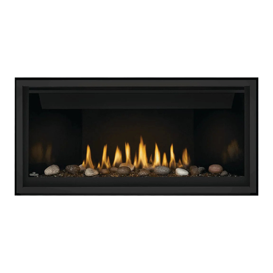
Ascent™ Linear Series
Product Name / Code
(MUST use title from Price Book)
ADD ____ ILLUSTRATED
ADD PRODUCT IMAGE
FOR INDOOR USE ONLY
NUMBER LABEL HERE
IF SEPARATE MANUALS, ADD "PLACE
OWNER'S MANUAL
ENGLISH
FRENCH PG. 67
(BL56 illustrated)
W415-
3036 / B / 08.19.22
Advertisement
Chapters
Table of Contents

Related Manuals for Napoleon Ascent Linear BL56


Summary of Contents for Napoleon Ascent Linear BL56
- Page 1 INTERTEK OWNER’S MANUAL BARCODE LABEL ON THE OWNER’S MANUAL” LOGO Wolf Steel Ltd., 24 Napoleon Rd., Barrie, ON, L4M 0G8 Canada / 103 Miller Drive, Crittenden, Kentucky, USA, 41030 Phone 1 (866) 820-8686 • www.napoleon.com • hearth@napoleon.com $10.00 W415- 3036 / B / 08.19.22...
- Page 2 safety information WARNING DANGER • This appliance is hot when operated and can cause severe burns if contacted. • Any changes or alterations to this appliance or its controls can be dangerous and is prohibited. HOT GLASS WILL CAUSE • Do not operate appliance before reading and BURNS.
- Page 3 patterns. RAAK HET GLAS NIET AAN TOT HET IS AFGEKOELD. DUTCH safety information LAAT KINDEREN NOOIT HET GLAS AANRAKEN. WARNING Dit apparaat is voorzien van een barrière die is ontworpen om het risico van brandwonden door het hete kijkglas te beperken. Deze barrière moet worden geïnstalleerd ter bescherming van kinderen •...
-
Page 4: Table Of Contents
table of contents general information flush recessed rates and efficiencies minimum clearance to combustible installation checklist enclosures installation overview alcove enclosure rating plate information 10.0 finishing mobile home installation hardware list 10.1 control cover installation dimensions 10.2 installing non-combustible board 10.3 minimum combustible mantel optional heat management system 12... -
Page 5: General Information
standard checklist Installer: please fill out the following information Customer: Address: Date of Installation: Location of appliance: Installer: Dealer/Distributor contact number: Serial #: Model: BL56NTE BL56PTE Natural Gas: Propane: 1.0 general information When the appliance is installed at elevations above 4,500ft (1372m), and in the absence of specific recommendations from the local authority having jurisdiction, the certified high altitude input rating shall be reduced at the rate of 4% for each additional 1,000ft (305m). -
Page 6: Installation Checklist
general information installation checklist GAS FIREPLACE INSTALLATION CHECKLIST Customer: Date Installed: Address: Installer: Model: Dealer: Serial #: Dealer Phone #: This checklist is a reference tool only. It is not intended as a substitute for the installation instructions. Fireplace Installation IF NOT, PLEASE EXPLAIN WHY? Is the fireplace level and secured? Are the factory supplied non-combustible materials installed? -
Page 7: Installation Overview
general information installation overview Recommended installation steps: 1. Determine venting requirements before deciding the final location of the appliance. 2. Install rough framing (refer to “rough framing” section). note: For Universal Heat Management installation steps, refer to the leaflet provided with the Universal Heat Management kit. - Page 8 general information WARNING • Always light the pilot whether for the first time or if the gas supply has run out, with the glass door opened or removed. • Provide adequate clearance for servicing and operating the appliance. • Provide adequate ventilation. •...
-
Page 9: Rating Plate Information
Recessed depth X” Profondeur d’encastré une face X” L’appareil doit être ventilé à l’aide de l’ensemble d’évacuation propre à Napoleon. Référez au *** Mantel X” from appliance opening *** Tablette X” de l’ouverture de l’appareil manuel d’installation pour les spécifications d’évacuation. Il est nécessaire de bien réinstaller et *** Maximum horizontal extension: *** L’extension horizontale maximale: X”. -
Page 10: Hardware List
general information hardware list Ref. # Description Quantity Sheet metal screw Sheet metal screw Quad drive sheet metal screw Sheet metal screw Self-drilling screw note: Only fasteners supplied with the appliance will be illustrated. W415-3036 / B / 08.19.22... -
Page 11: Dimensions
dimensions 2.0 dimensions *Finishing flange depth (the finishing flange defines the perimeter of the fireplace opening; framing or finishing materials must NEVER encroach inside the finishing flange). W415-3036 / B / 08.19.22... -
Page 12: Optional Heat Management System
dimensions optional heat management system The Universal Heat Management system is an optional gravity vent kit that allows you to manage the heat produced by the appliance at and around the fireplace. We recommend installing the Universal Heat Management system kit during the installation of the appliance BEFORE the gas is installed. -
Page 13: Venting Requirements
3.0 venting requirements venting requirements note: The minimum clearances from the top of the horizontal vent pipe to combustible materials may be reduced from 3” (76mm) to 1” (25mm) in those installations with a minimum 38” (96.5cm) vertical vent rise made immediately off the fireplace collar. -
Page 14: Typical Venting Installation
This template must be used in conjunction with templates 7.2.1 or 7.2.2, depending on termination shape (i.e. round, or round and square). See appropriate templates folder. venting requirements For optimum fl ame appearance and appliance performance, keep the vent length and number of elbows to a minimum. The air terminal must remain unobstructed at all times. - Page 15 venting requirements special vent installation (periscope termination) Use the periscope kit to locate the air termination above grade. The periscope must be installed so that when final grading is completed, the bottom air slot is located a minimum 12” (30.5cm) above grade. The maximum allowable vent length is 10’...
- Page 16 venting requirements 4/7” vent clearance to combustibles If necessary, 5/8” venting can be reduced to 4/7” venting (see “converting from 5/8” to 4/7” venting section) The minimum clearances around the horizontal vent pipe to the combustible material is 1" (25.4mm) in installations with a minimum of 38”...
- Page 17 venting requirements converting from 5/8" to 4/7" venting USE MILL PAC TO SEAL REDUCER TO THE APPLIANCE EXHAUST COLLARS. USE RED SILICONE TO SEAL REDUCER TO THE AIR INTAKE COLLARS. USE RED SILICONE TO SEAL REDUCER TO THE AIR INTAKE COLLARS. W415-3036 / B / 08.19.22...
-
Page 18: Minimum Air Terminal Location Clearances
venting requirements minimum air terminal location clearances Covered balcony applications ††* ≤ 15 feet = 3 feet = 2 x ACTUAL (0.9m) (4.6m) note: INSTALLATIONS Wall terminals are for illustration purposes only. Size and shapes may vary. Wall terminal CANADA U.S.A. -
Page 19: Vent Application Flow Chart
venting requirements vent application flow chart Top Exit Horizontal Termination Vertical Termination Vertical rise is equal Vertical rise is equal Vertical rise is less Vertical rise is less to or greater than the to or greater than the than horizontal run than horizontal run horizontal run horizontal run... -
Page 20: Horizontal Termination
venting requirements horizontal termination ) ≤ (V See graph to determine the required vertical rise V Simple venting configuration (only one 90° elbow) the required horizontal run H 40 (12.2) 39 (11.9) Required vertical 30 (9.1) rise in feet (meters) V 20 (6.1) 10 (3.1) 12.5... - Page 21 venting requirements ) > (V Simple venting configuration See graph to determine the required vertical rise V for the required horizontal run H (only one 90° elbow) 150 (381) 147 (373) REQUIRED VERTICAL 100 (254) RISE IN INCHES (CENTIMETERS) V 57 (145) 50 (127) 14.875 (38)
-
Page 22: Vertical Termination
venting requirements vertical termination ) < (V Simple venting configurations. See graph to determine the required vertical rise V for the required horizontal run H 40 (12.2) 30 (9.1) Required vertical rise in feet 20 (6.1) (meters) V 10 (3.1) 3 (0.9) (1.5) (3.1) - Page 23 venting requirements ) > (V Simple venting configurations. See graph to determine the required vertical rise V for the required horizontal run H 20 (6.1) 19 (5.8) Required vertical rise in feet 10 (3.1) (meters) V 3 (0.9) 10 (3.1) (7.6) (9.1) (1.5)
-
Page 24: Vent Shield Installation
venting requirements vent shield installation #2 X2 A. Form vent shield to a 90° angle (as illustrated in installation step above). B. Install the vent shield by securing it to top of appliance using 2 screws (supplied). C. Adjust vent shield top to suit horizontal run. W415-3036 / B / 08.19.22... - Page 25 4.0 rough framing rough framing note: When using optional fi nishing accessories, the framing dimensions and fi nishing materials may differ from what is outlined in the section below; refer to the leafl et instructions supplied in the accessory kit for specifi c framing and fi nishing specifi cations.
-
Page 26: Rough Framing
rough framing minimum framing dimensions note: The minimum clearances from the top of the horizontal vent pipe to combustible materials may be reduced from 3” (76mm) to 1” (25mm) in those installations with a minimum 38” (96.5cm) vertical vent rise made immediately off the appliance collar. - Page 27 rough framing Before framing your appliance, determine vent requirements before deciding the final location of the appliance. After rough framing, place the appliance in its final position. 18 9/16” (47.1cm) 56 1/2” W415-3036 / B / 08.19.22...
-
Page 28: Venting Installation
venting installation 5.0 venting installation WARNING • Ensure to unpack all loose materials from inside the fi rebox prior to connecting the gas and electrical supply • If your appliance is supplied with a remote, ensure the remote receiver is in the “OFF” position prior to connecting the gas and electrical supply to the appliance. -
Page 29: Horizontal Installation
venting installation horizontal installation WARNING • The fi restop assembly must be installed with the vent shield to the top. • Terminals must not be recessed into a wall or siding more than the depth of the return fl ange of the mounting plate. -
Page 30: Vertical Installation
venting installation vertical installation This application occurs when venting through a roof. Installation kits for various roof pitches are available from your authorized dealer / distributor. See the “accessories” section to order specifi c kits required. 10 3/4" 10 3/4" (273mm) A. -
Page 31: Using Either Flexible Or Rigid Vent
venting installation using either flexible or rigid vent components WARNING • Do not allow the inner fl ex pipe to bunch up on horizontal or vertical runs and elbows. Keep it pulled tight. • Spacers are attached to the inner fl ex pipe at predetermined intervals to maintain an even air gap to the outer fl ex pipe. -
Page 32: Vertical Air Terminal Installation
venting installation 5.4.2 vertical air terminal installation WARNING • Maintain a minimum 2” (51mm) space between the air inlet base and the storm collar. note: Fastening hardware provided with appropriate roof terminal and liner kits. Fasten the roof support to the roof using 6 screws. The roof support is optional. -
Page 33: Using Rigid Vent Components
venting installation using rigid vent components 5.5.1 horizontal air terminal installation Move the appliance into position. Measure #10x2" the vent length required between terminal and SCREWS appliance taking into account the additional CAULKING length needed for the fi nished wall surface and any 2”... -
Page 34: Vertical Air Terminal Installation
venting installation 5.5.2 vertical air terminal installation WARNING • Maintain a minimum 2” (51mm) space between the air inlet base and the storm collar. note: Fastening hardware provided with appropriate roof terminal and liner kits. Before attaching elbows to the collars on the back of the appliance, 1 1/2” (38.1mm) will need to be trimmed off the 4”... -
Page 35: Restricting Vertical Vents
venting installation 5.5.3 restricting vertical vents WARNING • Turn off gas and electrical supply before servicing the appliance. • Appliance may be hot, do not service until appliance is cool. • For safe and proper operation of the appliance, follow the venting instruction exactly. •... -
Page 36: Electrical Information
venting installation 6.0 electrical information hard wiring connection It is necessary to hard wire this appliance. This appliance must be electrically connected and grounded in accordance with local codes. In the absence of local codes, use the current CSA C22.1 Canadian Electrical Code in Canada or the ANSI/NFPA 70-1996 National Electrical Code in the United States. -
Page 37: Battery Back-Up Installation
electrical information battery back-up installation WARNING • Ensure the gas and electrical power to the appliance is turned off. • Appliance may be hot, do not service until the appliance has cooled. note: In the event of a power failure, your appliance can be operated using a USB power bank as a battery back-up. Before beginning installation, turn off the gas and disconnect the electrical power supply from the appliance. -
Page 38: Wiring Diagram
electrical information wiring diagram WARNING • Do not wire 110 volts to the valve or wall switch. W010-2763 (NG) W190-0195 (PF0 CONTROL BOARD) W010-2808 (P) PILOT SENSOR PILOT SPARK ROD WIRE HARNESS W750-0497 W725-0062 (NG) W725-0063 (P) (GAS VALVE) ORANGE GREEN BLACK POWER CORD... -
Page 39: Gas Installation
7.0 gas installation electrical information WARNING • Risk of fi re, explosion, or asphyxiation. Ensure there are no ignition sources such as sparks or open fl ames. • Support gas control when attaching gas supply pipe to prevent damaging gas line. •... -
Page 40: Operation
operation 8.0 operation WARNING • If you do not follow these instructions exactly, a fi re or explosion may result causing property damage, personal injury, or loss of life. • If applicable, always light the pilot whether for the fi rst time or if the gas supply has run out with the glass door opened or removed. -
Page 41: Pilot On Demand
In order to start your pilot, turning the main burner on with the switch, remote or thermostat and then turning it off will reactivate the continuous pilot mode and reset the seven day timer. For further information, refer to www.napoleon.com/pilotondemand. (Fig. 2) (Fig. -
Page 42: Finish Framing
finish framing 9.0 finish framing nailing tab installation #1 X4 Use one screw to secure the short side of the nailing bracket to the appliance. Repeat for 3 other locations. note: Adjust bracket to suit your desired finishing material. Bend tabs 180º upwards and secure to header. -
Page 43: Flush
finish framing flush WARNING • Do not build into this area - it must be left clear to provide adequate clearance for the vent in this 14” (35.6cm) wide area centered along the front of the appliance. The appliance should be in its final location before framing. -
Page 44: Recessed
finish framing recessed I ** Ceiling Drywall 39 3/8” (100cm) 18 9/16” (47.1cm) * Allow for finished floor and hearth thickness when setting these 56 1/2” dimensions. 84” (213cm) ** 2” x 4” frame can be “backed” with 3/4” ply to support TV mounting 3 1/2”... -
Page 45: Minimum Clearance To Combustible Enclosures
finish framing minimum clearance to combustible enclosures 3" [76.2mm] minimum all sides for vertical venting. Vent shield Non-combustible Combustible 8” (20.3cm) 3” (76.2mm) 0” if non-combustible finishing is used such as brick and stone. Center of 1”(25.4mm) vent pipe Top of to vent sides combustible opening... -
Page 46: Finishing
finishing 10.0 finishing WARNING • Risk of fire! • Never obstruct the front opening of the appliance. • The front of the appliance must be finished with any non-combustible materials such as brick, marble, granite, etc., provided that these materials do not go below the specified dimension, as illustrated. •... -
Page 47: Installing Non-Combustible Board
finishing 10.2 installing non-combustible board WARNING C O M B U S • Non-combustible facing material must not project more than 4” (102mm) from the face of the door (all three T I B L sides). If greater projections are desired, increase the clearance to the sides and top by 2” (51mm) for every additional 1”... -
Page 48: Minimum Combustible Mantel Clearances
finishing 10.3 minimum combustible mantel clearances Combustible mantel clearance can vary according to the mantel depth. Use the graph to help evaluate the clearance needed. MANTEL DEPTH Appliance Opening Hood MANTEL DIMENSIONS Height Depth 27 1/2” (69.9cm) 12” (30.5cm) 2" (51mm) 14”... -
Page 49: Clearances Around Appliance (Tv And Valuable Objects)
finishing 10.4 clearances around appliance (TV and valuable objects) Flush installation without Flush installation with Recessed installation with mantel mantel protrusion 6” min. 6” min. TV bracket The volume of TV bracket TV bracket air must be added to the enclosure to accomodate 2.5”... -
Page 50: Safety Barrier & Glass Door Installation / Removal
finishing 10.5 safety barrier & glass door installation / removal WARNING • Glass may be hot. Do not touch glass until cooled. • If equipped with door latches that are part of a safety system, they must be properly engaged. Do not operate the appliance with latches disengaged. -
Page 51: Glass Media Installation
finishing 10.6 glass media installation WARNING • Clean the glass media prior to installation. Before applying the cleaned glass, ensure that it is dry. • Do not change or substitute the glass media material provided with this appliance. If replacing, use only the replacement glass media available from your local authorized dealer / distributor. -
Page 52: Optional Blower Installation
finishing 10.7 optional blower installation WARNING • Ensure the appliance is completely cool before starting installation. • To avoid danger of suffocation, keep the packaging bag away from babies and children. Do not use in cribs, beds, carriages or play pens. This bag is not a toy. Knot before throwing away. Remove the safety barrier by lifting it up and off of the appliance. -
Page 53: Restricting Vertical Vents
finishing 10.8 restricting vertical vents Vertical installations may display a very active fl ame. If this appearance is not desirable, the vent exit must be restricted using a restrictor vent kit. Refer to the “replacement parts” section of the owner’s manual for the appropriate kit. -
Page 54: Pilot Burner Adjustment
finishing 10.10 pilot burner adjustment Adjust the pilot screw to provide properly sized fl ame. Turn in a clockwise direction to reduce the gas fl ow. ODS - MILLIVOLT Check Pressure Readings: Inlet pressure can be checked by turning screw (A) counter- clockwise 2 or 3 turns and then placing pressure gauge tubing over the test point. -
Page 55: Maintenance
11.0 maintenance finishing WARNING • Turn off the gas and electrical power before servicing the appliance. • Appliance may be hot. Do not service until appliance has cooled. • Do not use abrasive cleaners on glass. • Do not paint the pilot assembly. This appliance and its venting system should be inspected before use and at least annually by a qualifi ed service person. -
Page 56: Annual Maintenance
maintenance This appliance is factory equipped with 4mm tempered glass. Use only replacement parts as supplied by the appliance manufacturer. DO NOT SUBSTITUTE MATERIALS. 11.2 annual maintenance 5.1.1 WARNING • Annual maintenance should be performed by a qualifi ed service technician •... -
Page 57: Replacement Parts
replacement parts 12.0 replacement parts WARNING • Failure to position the parts in accordance with this manual or failure to use only parts specifi cally approved with this appliance may result in property damage or personal injury. Contact your dealer for questions concerning prices and policies on replacement parts. Normally, all parts can be ordered through your Authorized dealer / distributor. -
Page 58: Overview
replacement parts W415-3036 / B / 08.19.22... -
Page 59: Valve Train Assembly
replacement parts W415-3036 / B / 08.19.22... -
Page 60: Troubleshooting
troubleshooting 13.0 troubleshooting WARNING • Always light the pilot whether for the fi rst time or if the gas supply has run out, with the glass door open or removed. • Turn off gas and electrical power before servicing the appliance. •... - Page 61 Check that venting is installed correctly. appliances). Room is in negative pressure; increase fresh air supply. troubleshooting symptom problem test solution Pilot will not light. Makes Wiring: short, loose, or damaged Verify the thermocouple/sensor is clean and the wiring is undamaged. Verify the interrupter block is not damaged or too tight.
- Page 62 Wire connector pins are bent. Straighten pins. symptom problem test solution Valve wiring is damaged. Replace valve. troubleshooting Lights or blower Control module switch in Verify ON/OFF switch is in the “I” position which denotes on. won’t function (if wrong position. symptom problem test solution...
-
Page 63: Warranty
Napoleon neither assumes, nor authorizes any third party to assume, on its behalf, any other liabilities with respect to the sale of this product. Napoleon will not be responsible for: over- fi ring, downdrafts, spillage caused by environmental conditions such as rooftops, buildings, nearby trees, hills, mountains, inadequate vents or ventilation, excessive venting confi gurations, insuffi cient makeup air, or negative air pressures which may or may not be caused by mechanical systems such as exhaust fans, furnaces, clothes dryers, etc. -
Page 64: Service History
15.0 service history service history W415-3036 / B / 08.19.22... - Page 65 service history W415-3036 / B / 08.19.22...
- Page 66 NAPOLEON CELEBRATING OVER 40 YEARS OF HOME COMFORT PRODUCTS 7200, Route Transcanadienne, Montréal, Québec H4T 1A3 24 Napoleon Road, Barrie, Ontario, Canada L4M 0G8 214 Bayview Drive, Barrie, Ontario, Canada L4N 4Y8 103 Miller Drive, Crittenden, Kentucky, USA 41030 De Riemsdijk 22, 4004 LC Tiel, The Netherlands Phone: 1-866-820-8686 napoleon.com...
- Page 67 IF SEPARATE MANUALS, ADD “PLACE LOGO PROPRIÉTAIRE BARCODE LABEL ON THE OWNER’S MANUAL” Wolf Steel Ltd., 24 Napoleon Rd., Barrie, ON, L4M 0G8 Canada / 103 Miller Drive, Crittenden, Kentucky, USA, 41030 Téléphone 1(866)820-8686 • www.napoleon.com • hearth@napoleon.com $10.00 W415-3036 / B / 08.19.22...
- Page 68 NEVER ALLOW CHILDREN TO TOUCH GLASS. A barrier designed to reduce the risk of burns from the hot consignes de sécurité viewing glass is provided with this appliance and must be installed for the protection of children and other at-risk AVERTISSEMENT individuals.
- Page 69 continue de s’éteindre, faire réparer. Garder propres le brûleur et le compartiment de contrôle. • Cet appareil ne devra être modifi é en aucun cas. • Ne laissez pas les ventilateurs souffl er directement sur l’appareil. Empêchez les courants d’air de modifi er consignes de sécurité...
- Page 70 table des matières information générale opération taux et efficacités veilleuse sur demande vérification d’installation ossature fini vue d’ensemble d’installation installation des supports de fixation information à propos de la plaque affluerant d’homologation encastrée installation dans une maison mobile dégagements minimaux de l’enceinte 111 liste des pièces installation en alcôve dimensions...
- Page 71 liste de vérification Installateur: veuillez rempli les informations suivants Client: Addresse: Date d’Installation: Location de l’appareil Installateur: Tél. du Détaillant/Distributeur: Nº de série: Modèle: Gaz Naturel: BL56NTE Propane: BL56PTE 1.0 information générale Lorsque l’appareil est installé à des élévations dépassant 4 500ft (1372m), et en l’absence de recommandations spécifiques de l’autorité...
- Page 72 information générales vérification d’installation LISTE DE VÉRIFICATION POUR L'INSTALLATION D'UN FOYER AU GAZ Client : Date d'installation : Adresse : Installateur : Modèle : Détaillant : N° de série : Téléphone : Cette liste de vérification est fournie uniquement à titre de référence. Elle n'est pas destinée à remplacer les instructions d'installation.
-
Page 73: Information Générale
information générale vue d’ensemble d’installation Étapes d’installation recommandés: 1. Determiner les exigences d’évacuation avant de determiner le position finale de l’appareil. 2. Installer l’encadrement approximatif (référez à la section « encadrement approximatif »). note: Pour les étapes d’installation du système de gestion thermique universelle, référez au feuillet fourni avec l’ensemble du système de gestion thermique universelle. - Page 74 information générale AVERTISSEMENT • Allumez toujours la veilleuse, que ce soit pour la première fois ou lorsque l’approvisionnement en gaz est épuisé, avec la porte vitrée ouverte ou retirée. • Prévoyez un accès suffisant pour entretenir et opérer l’appareil. Assurez-vous d’une quantité suffisante d’air de ventilation.
-
Page 75: Information À Propos De La Plaque
Recessed depth X” Profondeur d’encastré une face X” L’appareil doit être ventilé à l’aide de l’ensemble d’évacuation propre à Napoleon. Référez au *** Mantel X” from appliance opening *** Tablette X” de l’ouverture de l’appareil manuel d’installation pour les spécifications d’évacuation. Il est nécessaire de bien réinstaller et *** Maximum horizontal extension: *** L’extension horizontale maximale: X”. - Page 76 information générale 1.6 liste des pièces Réf. No. Description Quantité Vis de feuille métallique Vis de feuille métallique Vis de feuille métallique à tête bombée Vis de feuille métallique Vis auto-perforante note: Seulement les attaches fournies avec l’appareil seront illustrées. W415-3036 / B / 08.19.22...
- Page 77 dimensions 2.0 dimensions *La profondeur de la bride definition (la bride de finition définit le périmètre de l’ouverture de la cheminée; les matériaux de charpente ou de finition NE JAMAIS empiété à l’intérieur de la bride de finition). W415-3036 / B / 08.19.22...
-
Page 78: Dimensions
dimensions système de gestion thermique (UHM) Le système de gestion thermique universelle est un ensemble optionnel d’évent par gravité permettant de gérer le chaleur produite par l’appareil à l’ouverture du foyer et autour. Nous recommandons d’installer l’ensemble du système de gestion thermique universelle pendant l’installation de l’appareil AVANT que le gaz de l’appareil est installé. -
Page 79: Exigences D'évacuation
3.0 exigences d’évacuation exigences d'évacuation note: Les dégagements minimaux entre le haut de l’évent horizontal aux matériaux combustibles peuvent être réduites de 3” (76mm) à 1” (25mm) dans les installations avec une évent vertical de minimum de 38” (96,5 cm) faite immédiatement au colet de l’appareil. - Page 80 haute température (RTV) ou d’un ruban d’aluminium approprié qui couvre toute la circonférence de chaque joint dans le système de ventilation. Cela garantira les meilleures performances dans chaque application et évite les problèmes de perfor- mance ou de condensation qui peuvent survenir dans les maisons construites « étroitement », en particulier dans les climats exigences d'évacuation froids.
- Page 81 exigences d'évacuation installations particulières d’évents (ensemble périscopique) Utilisez l’ensemble périscopique afin de positionner la terminaison au-dessus du niveau du sol. L’ensemble périscopique doit être installé de façon à ce que la fente d’air du bas soit située à un minimum de 12 pouces (30,5cm) au-dessus du niveau du sol.
- Page 82 exigences d'évacuation dégagement de ventilation aux combustibles 4/7” Si nécessaire, l’évacuation de 5/8” peut être réduit à 4/7” (voir la section « conversion de l’évacuation de 5/8” à 4/7” »). Les dégagements minimaux autour du tuyau d’évent horizontal vers le matériau combustible est 1” (25,4 mm) dans des installations avec une élévation verticale de minimum de 38”...
- Page 83 exigences d'évacuation conversion de l’évacuation de 5/8” à 4/7” UTILISEZ L’ADAPTATEUR PAC TO SEAL ADAPTATEUR À L’APPAREIL COLLIERS. UTILISEZ SILICONE D’HAUTE TEMPÉRATURE POUR SCELLER L’ADAPTATEUR À L’APPAREIL COLLIERS. UTILISEZ SILICONE D’HAUTE TEMPÉRATURE POUR SCELLER L’ADAPTATEUR À L’APPAREIL COLLIERS. W415-3036 / B / 08.19.22...
-
Page 84: Emplacements Et Dégagements Minimaux
exigences d'évacuation 3.2 emplacements et dégagements minimaux de la terminaison Applications pour balcon couvert ††* = 3 feet ≤ 15 feet = 2 x ACTUAL (0.9m) (4.6m) note: INSTALLATIONS Les terminaux du mur sont à des fi ns d’illustration seulement. La taille et les formes peuvent varier. Mesures des terminaux prises à... -
Page 85: Charte D'application Des Évacuations
exigences d'évacuation 3.3 charte d’application des évacuations Évacuation sur le dessus Terminaison horizontale Terminaison verticale La course verticale La course verticale La course verticale est La course verticale plus grande ou égale à est plus petite que la est plus grande ou est plus petite que la la course horizontale course horizontale... -
Page 86: Terminaison Horizontale
exigences d'évacuation 3.6 terminaison horizontale ) ≤ (V Configuration d’évacuation simple (un coude de 90° Consultez le graphique pour déterminer la course seulement) verticale nécessaire V par rapport à la course horizontale requise H 40 (12,2) 39 (11,9) Course verticale 30 (9,1) requise en pieds (mètres) V... - Page 87 exigences d'évacuation ) > (V Configuration d'évacuation simple Consultez le graphique pour déterminer la course verticale nécessaire V (un coude de 90° seulement) par rapport à la course horizontale requise H 150 (381) 147 (373) COURSE VERTICALE 100 (254) REQUISE EN POUCES (CEN- TIMÈTRES)V 57 (145)
-
Page 88: Évacuation À L'arrière Terminaison Verticale
exigences d'évacuation 3.7 évacuation à l’arrière terminaison verticale ) < (V Consultez le graphique pour détermine la course verticale Configuration d’évacuation simple. nécessaire V par rapport à la course horizontale requise H 40 (12,2) 30 (9,1) Course verticale requise en pieds 20 (6,1) (mètres) V 10 (3,1) - Page 89 exigences d'évacuation ) > (V Configuration d'évacuation simple. Consultez le graphique pour déterminer la course verticale nécessaire V par rapport à la course horizontale requise H 20 (6.1) 19 (5.8) COURSE VERTICALE REQUISE EN PIEDS 10 (3.1) (MÈTRES) V 3 (0.9) 10 (3.1) (7.6) (9.1)
-
Page 90: Installation De L'écran Protecteur
exigences d'évacuation installation de l’écran protecteur #2 X2 A. Bouclier de vent forme un angle de 90° (comme illustré à l’étape d’installation ci-dessus). B. Installez le pare vent en le fixant en haut de l’appareil à l’aide de 2 vis (fournies). C. -
Page 91: Ossature Approximatif
4.0 ossature approximatif ossature approximatif note: Lorsque vous installez les accessoires de fi nition optionelles, les dimensions de l’ossature et les matériaux de fi nition peuvent différer de ce qui est décrit dans ces instructions ci-dessous, voir les instructions fournies dans le trousse de l’accessoire pour les spécifi cations détaillées. -
Page 92: Dimensions Minimaux De L'encadrement
ossature approximatif dimensions minimaux de l’encadrement note: Les dégagements minimaux entre le haut de l’évent et les matériaux combustibles peut être réduite de 3” (76mm) à 1” (25mm) dans ces installations avec un évent verticale de minimum 38” (96,5cm) faire immédiatement au collet de l’appareil. - Page 93 ossature approximatif Avant d’encadrer votre appareil, déterminez les exigences d’évacuation avant de décider de l’emplacement final de l’appareil. Après l’ossature approximatif, placez l’appareil dans sa position finale. 18 9/16” (47,1cm) 56 1/2” W415-3036 / B / 08.19.22...
-
Page 94: Installation D'évacuation
installation d'évacuation 5.0 installation d’évacuation AVERTISSEMENT • Avant d’effectuer les branchements pour l’alimentation en gaz et électronique, assurez-vous de retirer toute composante non fi xée à l’intérieur de la chambre de combustion. • Si votre appareil comprend un système de télécommande, assurez-vous que le récepteur est à la position «... -
Page 95: Installation Horizontale
installation d'évacuation 5.1 installation horizontale AVERTISSEMENT • L’espaceur coupe-feu doit être installé avec l’écran protecteur orienté vers le haut. • La terminaison ne doit pas être enchâssée dans le mur ou le revêtement extérieur plus que l’épaisseur de la bride de la plaque de montage. •... -
Page 96: Installation Verticale
installation d'évacuation 5.2 installation verticale Cette confi guration s’applique lorsque l’évacuation se fait à travers un toit. Des ensembles d’installation pour les différentes pentes de toit sont disponibles chez votre détaillant autorisé. Voir la section « accessoires » dans le manuel du propriétairepour commander l’ensemble spécifi que dont 10 3/4"... -
Page 97: Installation De La Terminaison Horizontale
installation d'évacuation utilisation de composants d’évacuation flexibles ou rigides AVERTISSEMENT • Ne laissez pas la gaine fl exible se tasser contre les courses horizontales ou verticales et les coudes. Gardez-la tendue. • Des espaceurs sont fi xés à la gaine fl exible à intervalles prédéterminés afi n de garder un espace vide avec le conduit extérieur. -
Page 98: Installation De La Terminaison Verticale
qu’illustré. Le système d’évacuation doit être soutenu Gaine flexible extérieure à environ tous les 3 pieds (0,9m) pour les courses intérieure verticales et horizontales. Utilisez des supports installation d'évacuation incombustibles afi n de maintenir le dégagement minimal aux matériaux combustibles. Calfeutrage Pour les Poêles seulement: De l’intérieur de la maison, scellez avec du scellant à... -
Page 99: Raccordement Des Évents À L'appareil
installation d'évacuation 5.4.3 raccordement des évents à l’appareil #2 (X6) REAR VENT TOP VENT - FLEX A. Raccordez la gaine fl exible intérieure à l’appareil. Fixez-la à l’aide d’au moins trois vis et rondelles lorsque vous utilisant une évent de 3”/5”, 4”/7” #8 X 1/2”... -
Page 100: Installation De La Terminaison Verticale
installation d'évacuation 5.5.2 installation de la terminaison verticale AVERTISSEMENT • Conserves un espace minimal de 2” (51mm) entre la base de la prise d’air et le collet de solin. note: Avant de fi xer les coudes aux collets à l’arriére de l’appareil, enlevez 1 1/2” (38.1mm) au collet de 4” (101.6mm) Matériel de fi xation fourni avec les ensembles de terminaison pour toit et raccord appropriée. -
Page 101: Renstreignant Des Évents Verticaux
installation d'évacuation 5.5.3 renstreignant des évents verticaux AVERTISSEMENT • Mettez hors tension de gaz et de l’alimentation électrique avant d’intervenir sur l’appareil. • Appareil peut être chaud, pas de service jusqu’à ce que l’appareil est refroidi. • Pour utilisation sûre et correcte de l’appareil, suivez les instructions d’évacuation exactement. •... -
Page 102: Schéma De Câblage
6.0 schéma de câblage schéma de câblage 6.1 branchement par câble Vous devez effectuer un branchement par câble avec cet appareil. Cet appareil doit être raccordé électriquement et mis à la terre conformément auix codes locaux. En l’absence de codes locaux, utilisez la version courante du Code Canadien de l’Électricité CSA C22.1 au Canada ou le National Electrical Code ANSI/NFPA aux États-Unis. -
Page 103: Installation Du Sauvegarde De Pile
schéma de câblage installation du sauvegarde de pile AVERTISSEMENT • Assurez-vous que le gaz et l’électricité de l’appareil sont coupés. • L’appareil peut être chaud, ne pas entretenir tant que l’appareil n’a pas refroidi. note: En cas de panne de courant, votre appareil peut être utilisé avec la banque d’alimentation USB comme sauvegarde de piles. -
Page 104: Schéma Câblage
schéma de câblage schéma câblage AVERTISSEMENT AVERTISSEMENT • • Ne raccordez pas l’interrupteur mural ou la soupape de gaz à l’alimentation électrique (110V). Ne raccordez pas l’interrupteur mural ou la soupape de gaz à l’alimentation électrique (110V). W010-2763 (GN) W190-0195 (PF0 CONTROL BOARD) W010-2808 (P) ASSEMBLAGE DE VEILLEUSE... -
Page 105: Branchement Du Gaz
7.0 branchement du gaz branchement du gaz AVERTISSEMENT • Risque d’incendie, d’explosion, ou d’asphyxie. Assurez-vous qu’il n’y ait aucune source d’allumage comme des étincelles ou une fl amme nue. • Soutenez le contrôle du gaz lorsque vous attachez le tuyau pour éviter de plier la conduite de gaz. •... -
Page 106: Opération
guide de fonctionnement 8.0 opération WARNING • If you do not follow these instructions exactly, a fi re or explosion may result causing property damage, personal injury, or loss of life. • If applicable, always light the pilot whether for the fi rst time or if the gas supply has run out with the glass door opened or removed. -
Page 107: Veilleuse Sur Demande
In order to start your pilot, turning the main burner on with the switch, remote or thermostat and then turning it off will reactivate the continuous pilot mode and reset the seven day timer. For further information, refer to www.napoleon.com/pilotondemand. (Fig. 2) (Fig. -
Page 108: Ossature Fini
opération 9.0 ossature fini installation des supports de fixation #1 X4 Utiliser une vis autotaraudeuse pour fixer la côté court du support de fixation à l’appareil. Répétez pour les 3 autres locations. note: Ajustez le support en fonction de votre matériau de finition désiré. Pliez les supports à... -
Page 109: Affluerant
ossature fini affluerant AVERTISSEMENT • Ne construisez pas dans cet espace de 14” (35,6cm) de largeur, centré le long de l’avant de l’appareil. Cet espace doit resté libre afin d’offrir un dégagement adéquat pour l’évacuation. Aucun matériaux combustible n’est permis. Plafond CEILING L’en-tête... -
Page 110: Encastrée
ossature fini encastrée Plafond I ** Ceiling Cloison Sèche Drywall * Tenez compte de l’épaisseur du 39 3/8” (100cm) plancher et du foyer lorsque vous définissez ces dimensions. 18 9/16” (47.1cm) ** Le cadre de 2” x 4” peut être « renforcé... -
Page 111: Dégagements Minimaux De L'enceinte
ossature fini 9.4 dégagements minimaux de l’enceinte 3" [76.2mm] minimum all sides for vertical venting. toute côtés d’évacation verticale. Vent shield Incombustible L’écran Non-combustible protecteur Combustible 8” (20.3cm) 3” 0” (0mm) si les (76.2mm) matériaux incombustibles sont 0” if non-combustible finishing is used such as brick and stone. -
Page 112: Finitions
finitions 10.0 finitions AVERTISSEMENT • Risque d’incendie. • N’obstruez jamais l’ouverture sur le devant de l’appareil. • Si la finition de la façade de l’appareil est fait, elle doit être faite de matériau incombustible comme de la brique, du marbre du granite, etc., sous réserve que ces matériaux ne dépassent pas la dimension spécifiée, comme illustré. -
Page 113: Matériau De Finition Incombustible
finitions 10.2 matériau de finition incombustible AVERTISSEMENT • Les matériaux de finition incombustibles ne doivent pas dépasser de plus 4” (102mm) la façade de la porte C O M B U S (sur toutes trois côtés). Si des projections plus grandes sont requises, augmentez les dégagements des T I B L côtés et du dessus de 2”... -
Page 114: Dégagements Minimaux De La Tablette Combustible
finitions 10.3 dégagements minimaux de la tablette combustible Le dégagement d’une tablette combustible à l’appareil peut varier selon la profondeur de la tablette. Utilisez le graphique pour vous aider à déterminer les dégagements nécessaires. Profondeur de MANTEL DEPTH la Tablette Ouverture de Appliance l’Appareil... -
Page 115: Dégagements Autour De L'appareil (Téléviseur Et Des Objets Précieux)
finitions 10.4 dégagements autour de l’appareil (téléviseur et des objets précieux) Installation affleurant sans un Installation affleurant avec un Installation enchâssées avec une saillie manteau manteau 6” min. 6” min. Support du téléviseur Support du Le volume d’air Support du téléviseur téléviseur doit être ajouté... -
Page 116: Installation / Enlèvement De L'écran De Protection Et La Porte
finitions 10.5 installation / enlèvement de l’écran de protection et la porte AVERTISSEMENT • La vitre peut être chaude. Ne touchez pas la vitre jusqu’à ce qu’elle ait refroidi. • Si équipé avec les loquets de porte qui font partie d’un dispositif de sécurité, ils doivent être adéquatement verrouillés. -
Page 117: Installation Des Braises Vitrifiées
finitions 10.6 installation des braises vitrifiées AVERTISSEMENT • Nettoyez les braises vitrifi ées avant d’installation. Assurez-vous qu’elles sont sèches avant de les disposer dans le plateau. • Ne changez pas ou ni substituez pas les braises vitrifi ées fournies avec cet appareil. En cas de remplacement, n’utilisez que les braises vitrifi ées de rechange disponibles chez votre détaillant autorisé. -
Page 118: Installation De La Soufflerie (Optionnel)
finitions 10.7 installation de la soufflerie (optionnel) AVERTISSEMENT • Assurez-vous que l’appareil est complètement refroidi avant de commender l’installation • Afin d’éviter les risques de suffocation, gardez le sac d’emballage loin des bébés et des jeunes enfants. Ne le laissez pas traîner dans les berceaux, les lits, les poussettes ou les parcs de jeu. Ce sac n’est pas un jouet. Nouez-le avant de la jeter. -
Page 119: Renstreignant Des Évents Verticaux
finitions 10.8 renstreignant des évents verticaux Certaines confi gurations d’évacuation verticales peuvent avoir une fl amme très active. Si cette apparence n’est pas désirée, la sortie du conduit d’évacuation doit être réduite en utilisant une plaque de restriction. Pour obtenir l’ensemble approprié, voir la section «... -
Page 120: Réglage De La Veilleuse
finitions 10.10 réglage de la veilleuse Ajustez la vis de la veilleuse pour obtenir une fl amme de taille normale. Tournez vers la droite pour réduire l’apport de gaz. Vérifi ez la pression: Pour vérifi er la pression d’arrivée, tournez la vis (A) vers la gauche ODS - MILLIVOLT deux à... -
Page 121: Entretien
11.0 entretien entretien AVERTISSEMENT • Coupez l’alimentation en gaz et l’alimentation électrique avant de procéder à l’entretien de l’appareil. • L’appareil peut être chaud. Attendez qu’il soit refroidi avant d’en faire l’entretien. • N’utilisez pas de produits abrasifs. • Ne peinture pas l’assemblage de la veilleuse. Cet appareil et son système d’évacuation devraient être inspectés avant la première utilisation et au moins une fois l’an par un technicien de service qualifi é. -
Page 122: Entretien Annuel
entretien 11.2 entretien annuel AVERTISSEMENT • Le caisson devient trés chaud lors du fonctionnement. Laissez l’appareil se refroidir complétement ou portez des gants antichaleur avant d’effectuer l’entretien. • Ne jamais aspirer des braises qui sont chaudes. • Ne peinturez pas l’assemblage de la veilleuse. •... -
Page 123: Pièces De Rechange
12.0 pièces de rechange pièces de rechange AVERTISSEMENT • Omettre de positionner les pièces conformément à ce manuel ou d’utiliser uniquement des pièces spécifi quement approuvées pour cet appareil peut causer des dommages matériels ou des blessures corporelles. Contactez votre détaillant pour les questions concernant les prix et la disponibilité des pièces de remplace- ment. -
Page 124: Vue D'ensemble
pièces de rechange W415-3036 / B / 08.19.22... -
Page 125: L'assemblage De La Soupape
pièces de rechange W415-3036 / B / 08.19.22... -
Page 126: Guide De Dépannage
13.0 guide de dépannage guide de dépannage AVERTISSEMENT • Allumez toujours la veilleuse, que ce soit pour la première fois ou lorsque l’approvisionnement en gaz est épuisé, avec la porte vitrée ouverte ou retirée. • Coupez l’alimentation en gaz et l’alimentation électrique avant de procéder à l’entretien de l’appareil. •... - Page 127 guide de dépannage symptôme problème solution La veilleuse ne s’allume Câblage: pénurie, connexion Vérifi ez qu’il n’y a pas de connexions desserrées du thermocouple ni sonde de fl amme. pas. Il y a du bruit mais desserrée (rectifi cation de la Vérifi ez l’interrupteur de bloc n’est pas endommagée ou trop serré.
- Page 128 fi ls sont courbeés. Câblage de la soupape est Remplacez la soupape. guide de dépannage endommagée symptôme problème solution Moteur tourne, les Les piles du récepteur sont Remplacez les piles. bips fréquent se faibles. produit. Lumières ou la souf- L’interrupteur de contrôle est Vérifi ez que l’interrupteur «...
-
Page 129: Garantie
14.0 garantie garantie Les produtits Napoléon sont fabriqués conformément aux normes strictes du Système de Gestion de la Qualité mondialement reconnu ISO 9001 : 2015. Les produits Napoléon sont conçus avec des composants et des matériaux de qualité supérieure, assemblés par des artisans qualifi és qui sont fi ers de leur travail. -
Page 130: Historique D'entretien
15.0 historique d’entretien garantie W415-3036 / B / 08.19.22... - Page 131 garantie W415-3036 / B / 08.19.22...
- Page 132 NAPOLÉON CÉLÈBRE PLUS DE 40 ANS D’EXISTENCE CONSACRÉS À LA CONCEPTION DE PRODUITS DE CONFORT 7200, Route Transcanadienne, Montréal, Québec H4T 1A3 24 Napoleon Road, Barrie, Ontario, Canada L4M 0G8 214 Bayview Drive, Barrie, Ontario, Canada L4N 4Y8 103 Miller Drive, Crittenden, Kentucky, USA 41030 De Riemsdijk 22, 4004 LC Tiel, Pays-Bas Téléphone: 1-866-820-8686...
Need help?
Do you have a question about the Ascent Linear BL56 and is the answer not in the manual?
Questions and answers