
Related Manuals for TERMOFOL TF-H1 Mark II

Summary of Contents for TERMOFOL TF-H1 Mark II
- Page 1 TERMOREGULATOR TERMOFOL TF-H1 Mark II INSTRUKCJA OBSŁUGI I KONFIGURACJI TERMOREGULATORA Instrukcja montażu Installation manual...
- Page 2 CHARAKTERYSTYKA I DANE TECHNICZNE Dziękujemy za zakup naszego produktu. Liczymy, że będziecie Państwo zadowoleni z korzystania z termoregulatora TERMOFOL TF-H1 Mark II. Jest to w pełni funkcjo- nalny sterownik instalacji i urządzeń grzewczych, zapewniający najwyższy komfort obsługi oraz precyzyjne i użyteczne funkcje, które pozwolą Państwu w pełni uzyskać...
- Page 3 INSTALACJA TERMOSTATU, POŁĄCZENIA ELEKTRYCZNE TERMOFOL TF-H1 Mark II to nowoczesny, wyposażony w panel sterujący LED, pro- gramowalny termoregulator przeznaczony do sterowania elektrycznymi systemami grzewczymi. Termoregulator odczytuje temperaturę z wewnętrznego i zewnętrzne- go czujnika temperatury, który jest dołączony w zestawie. Przed montażem, demon- tażem, czyszczeniem, dokonywaniem przeglądu, zawsze odłącz termoregulator od...
- Page 4 Rys. 3 sensor Przykład umiejscowienia termoregulatora Termoregulator może być instalowa- ny w standardowej puszcze ścien- nej 86mm lub europejskiej okrągłej 60mm. Rys. 4 1. Podłącz zasilanie oraz pozostałe przewody zgodnie ze schematem podłączenia. Rys. 5 2. Przykręć blachę montażową do puszki montażowej. Rys.
- Page 5 Rys. 7 Przykład właściwego podłączenia termoregulatora W celu instalacji termoregulatora w puszce elektrycznej i podłączeń elektrycznych należy bardzo delikatnie (tak by nie urwać taśmy połączeniowej) otworzyć obudo- wę, zdejmując zespół wyświetlacza zgodnie z instrukcją przedstawioną na rysunku 4. Ekran należy delikatnie przesunąć w górę. (odwrotnie niż przedstawia to rys.6) Instalacja termoregulatora powinna być...
- Page 6 W stanie włączonego termoregulatora dotknięcie przycisku przez 3–5 sekund pozwala użytkownikowi zaprogramować harmonogram pracy termoregulatora. W stanie wyłączonego termoregulatora dotknięcie tego przycisku przez 3–5 sekund pozwala konfigurować ustawienia zaawansowane B. W stanie włączonego termoregulatora krótkie naciśnięcie daje możliwość ustawie- nia godziny i dnia tygodnia. Natomiast dotknięcie przez 3-5 sekund pozwala akty- wować...
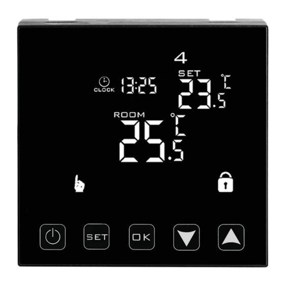
- Page 7 IKONY WYŚWIETLACZA – SPECYFIKACJA ikona potwierdzająca pracę ter- AUTO mostatu w trybie automatycznego tryb manualny harmonogramu AUTO tymczasowy tryb manualny zegar CLOCK blokada przycisków tryb wakacyjny wyłączenie ogrzewania, spo- zewn. czujnik temperatury wodowane wysoką tempera- turą podłogi USTAWIENIE HARMONOGRAMU PRACY W stanie włączonego termoregulatora naciśnij przycisk przez 3–5 sek.
- Page 8 Zakres wartości Wartość Rodzaj parametru parametru fabryczna Kalibracja czujnika –9 °C ÷ 9 °C –1 temperatury powietrza Histereza 0,5–2,5 °C 1 °C 0: blokada częściowa 1: Blokada przycisków blokada pełna 0: Urządzenie przyjmuje swój stan sprzed zaniku zasilania Funkcja pamięci stanu 1: Urządzenie pozostaje urządzenia przed zanikiem wyłączone po powrocie...
- Page 9 Zakres wartości Wartość Rodzaj parametru parametru fabryczna N1: tylko wewnętrzny czuj- nik temp. włączony N2: tylko zewn. czujnik temp. włączony N3: włączony wewnętrzny Wybór czujników temperatury – i zewnętrzny czujnik sposobu kontroli temperatury temperatury – utrzyma- nie zadanej temperatury powietrza z kontrolą temperatury urządzenia grzewczego Funkcja odkamieniania...
- Page 10 Pomiar rezystancji czujnika NTC przeprowadzamy miernikiem uniwersalnym usta- wionym na pomiar rezystancji w zakresie od 20 kΩ. Pomiar rezystancji czujnika pod- łogowego, ma charakter kontrolno-informacyjny i ma na celu, podobnie jak pomiar rezystancji systemu grzewczego wykluczyć uszkodzenie przewodu przyłączeniowe- go (np. jego naderwanie przy wciąganiu do peszla) czy też samego czujnika NTC. Orientacyjne wartości rezystancji w zależności od temperatury podłoża instalacji podano w poniższej tabeli.
-
Page 11: Miejsce Instalacji
KARTA GWARANCYJNA MIEJSCE INSTALACJI DANE INSTALATORA Nazwa firmy Imię i Nazwisko Adres (ulica, nr) Miejscowość Telefon Data Podpis instalatora Pieczątka instalatora www.termofol.pl biuro@termofol.pl +48 (12) 376 86 00... - Page 12 THERMOREGULATOR TERMOFOL TF-H1 Mark II OPERATING AND CONFIGURATION MANUAL OF THERMOREGULATOR Installation manual...
-
Page 13: Characteristics And Technical Data
Thank you for purchasing our product. We hope that you will enjoy using the TERMOFOL TF-H1 Mark II thermoregulator. It is a fully functional controller of instal- lations and heating devices providing the highest comfort of use, as well as precise and useful functions that will allow you to fully control the climate in your rooms. - Page 14 TERMOSTAT INSTALLATION, ELECTRIC CONNECTIONS The TF-H1 Mark II is a modern, programmable thermoregulator equipped with LED control panel intended for controlling electric heating systems. The thermoregula- tor reads the temperature from the built-in sensor and external temperature sen- sors, which is included in the kit along with the thermoregulator. Wi-Fi function and the manufacturer’s dedicated TERMOFOL SMART application enable to supervise...
- Page 15 Fig. 3 sensor Example of thermoregulator location Thermoregulator can be installed in a standard 86mm wall junction box or in a 60mm European round junction box. Fig. 4 1. Connect the power supply and other wires as shown in the wiring diagram.
- Page 16 Fig. 7 Example of correct connection of a thermoregulator For the purpose installation of the thermoregulator, in the junction box and making the electric connections, you should open its housing very gently (so as not to bre- ak the connection tape) by removing the display assembly according as shown in Figure 2.
- Page 17 When the thermoregulator ON, touching the button for 3-5 seconds enables the user to program the thermoregulator operating schedule. When the thermoregulator OFF, touching the button for 3-5 seconds enab- les the user to configure the advanced B settings. When the thermostat is ON, a short press enables the user to set the time and day of the week.
- Page 18 DISPLAY ICONS – SPECIFICATION icon confirming thermo- AUTO stat operation in the automatic manual mode schedule mode AUTO temporary manual mode clock CLOCK holiday mode button lock switching off the heating, caused by high temperature of floor external temperature sensor SETTING THE OPERATING SCHEDULE When the thermoregulator is on, press the button for 3-5 seconds.
- Page 19 Range of parameter Type of function / parameter Factory value value / function option Calibration of air temperature –9 °C ÷ 9 °C –1 sensor Hysteresis 0,5–2,5 °C 1 °C 0: partial locking / 1: full Locking of buttons locking 0: Device restores its state prior to a power failure Memory function of device status...
- Page 20 Range of parameter Type of function / parameter Factory value value / function option N1: only built-in tempera- ture sensor is on N2: only external tempera- ture sensor is on Selection of temperature sensors – N3: built-in and external method of controlling the tempe- temperature sensor are on rature –...
- Page 21 The resistance of the NTC sensor is measured with a universal meter set to measure resistance in the range from 20 kΩ. The measurement of the floor sensor resistance is of control and informational nature, and its purpose is, similarly to the measure- ment of the heating system resistance, to exclude damage of the connection wire (e.g., its tearing when pulling it into the conduit) or the NTC sensor itself.
-
Page 22: Warranty Card
WARRANTY CARD PLACE OF INSTALLATION FITTER’S DETAILS Name of company Forename and surname Address (street, no.) Postal Locality code Tel. Date Fitter’s signature Fitter’s stamp www.termofol.com biuro@termofol.pl +48 (12) 376 86 00...
Need help?
Do you have a question about the TF-H1 Mark II and is the answer not in the manual?
Questions and answers